

Page 1
HDMIGEN
High-Definition
Multimedia Interface
Pattern Generator
Quick Guide
HDMIGEN
2
TABLE OF CONTENTS
1. Features and
Specifications
..............................................................
3
Features ...............................................................................................
3
Specifications ......................................................................................
3
RS-232 Protocol ...................................................................................
3
2. Front Panel Operation ........................................................................
4
3. Rear Panel Installation and Connection .........................................
5
4. TIMING Table ......................................................................................
6
5. PATTERN Table ....................................................................................
7
6. Remote Control ................................................................................. 12
7. RS232 Remote Control Application.................................................. 13
7.1 Main Window................................................................................ 13
7.2 Select COM port to control ........................................................ 13
7.3 Switch TIMING ............................................................................... 14
7.4 Switch PATTERN ............................................................................ 15
7.5 Programming TIMING/PATTERN .................................................. 16
7.6 EDID ............................................................................................... 18
7.6.1 Read EDID ............................................................................ 18
7.6.2 Memory of EDID .................................................................... 18
7.6.3 Upload EDID .......................................................................... 18
7.6.4 Write EDID .............................................................................. 18
Page 2
3
1. Features and Specifications
Features
?
Provides total 35 Timings and 39 Patterns
? Supports HDCP signal
verification
pattern (P39)
?
On-panel LED display and LED indicators
? Remote control
?
Supports RS-232 control,
specific
PC application included
Specifications
? HDMI v1.2, HDCP 1.1 and DVI 1.0 compliant
? HDMI Frequency bandwidth: 1.65Gbps (single link)
? Input: Audio L/R x 1 and Toslink S/PDIF x 1
? Output: HDMI female port (type A connector) x 1
? Power Supply: 5VDC 3.2A power supply (AC 90-240V)
? Weight: 1.5Kgs
?
Dimensions: 280(W) x 130(D) x 44(H) mm
RS-232 Protocol
Pin Definititon
Pin
Definition
1 NC
1 NC
2 TxD 2
3 RxD 3
4 NC
?
4
5 GND
?
5
6 NC 6
7 NC 7
8 NC 8
9 NC 9
RxD
TxD
NC
GND
NC
NC
NC
NC
4
2. Front Panel Operation
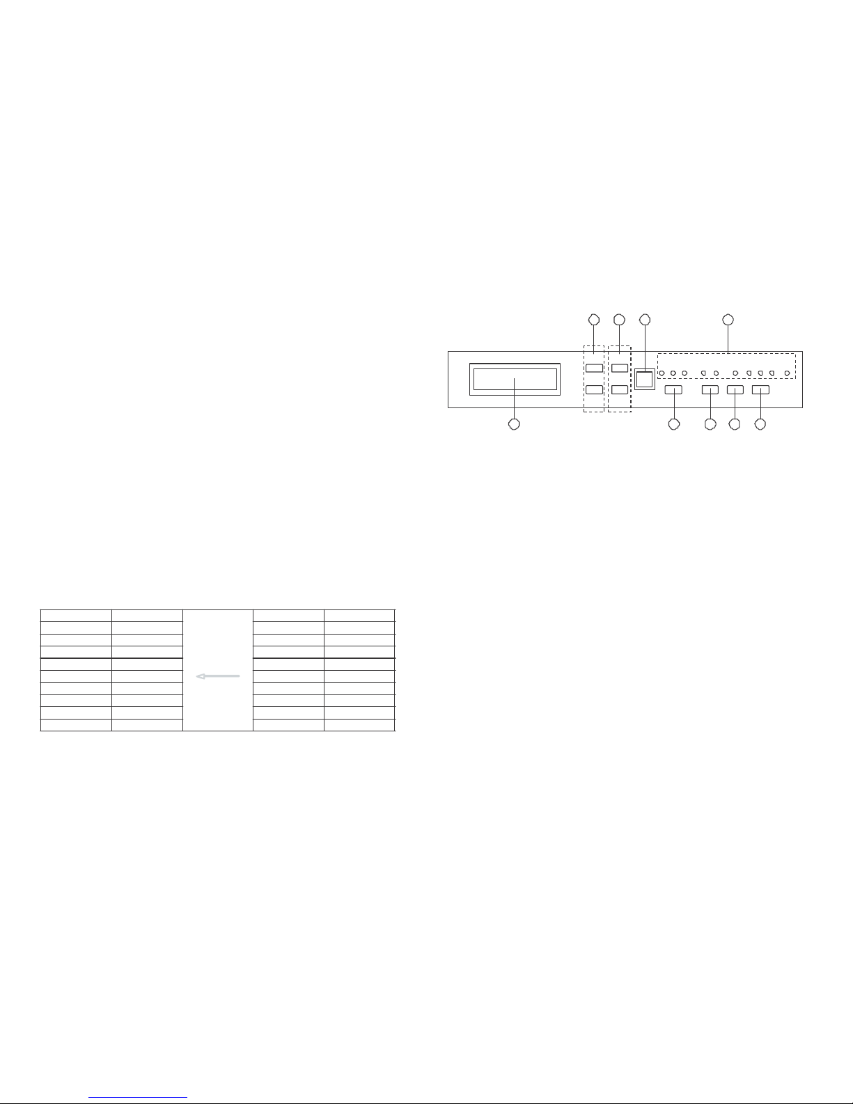
1 2 3 4
? ?
EXT
EXT
INT
L/R
OPT.
SINEWAVE
HDMI
DVI AUTO
RGB
YUV
YUV
(4:4:4)
(4:4:4)
(4:2:2)
HDCP
TIMING
PATTERN
? ?
HDMIGEN HDMI PATTERN GENERATOR
5 6 7 8 9
1. Pattern Selection:
From P01 ~ P39
2. Resolution/Freq. Selection:
From T01 ~ T35
3. Remote control sensor
4. HDCP LED Indicator:
The LED will illuminate when pattern "P39 HDCP-Produce" is selected and
the output display (TV, monitor, etc.) supports HDCP. To unilluminate the
HDCP indicator (Switch Off HDCP), frist step to change to other pattern
and then changed either Timing, HDMI/DVI output selection or color
space selection.
5. Display of PATTERN/TIMING:
Upper line: Number of TIMING, Resolution and Frequency (Example: T01
640x480-60)
Lower line: Number of PATTERN and name of PATTERN (Example: P01
WHITE)
6. Audio Source Selection:
External L/R
External Optical
Internal Sinewave
7. HDMI/DVI Output Selection
8. Turn on/off AUTO pattern
random-cycling
9. Color Space Selection:
RGB 4:4:4
YUV 4:4:4
YUV 4:2:2
Page 3
5
3. Rear Panel Installation and Connection
1 2 3 4
OVERSCAN
RS-232
HDMI OUT
OPTICAL
INPUT
L
R
DC 5V
POWER
5 6
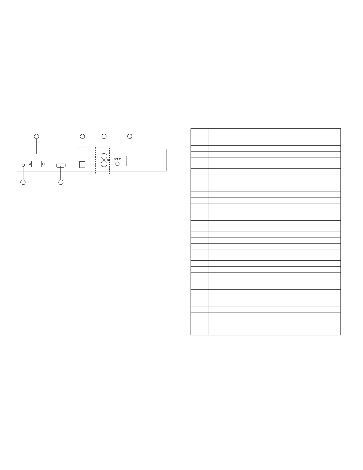
1. RS232 Communication Port:
Connect to the COM1 or COM2 port of your PC, and control the unit
remotely using the application provided.
2. Audio Optical Input
3. Audio L/R Input
4. Power Switch
5. Fill-Screen Button:
For some modals of TV/monitor, the video signal can not
fill
the screen of
display completely, to correct this problem, press the button once when
the power is on.
6. HDMI OUT:
The HDMI output can be connected to a HDMI display using HDMI cable,
or to a DVI display using HDMI to DVI cable.
6
5. TIMING Table
No. Resolution Frequency (Hz)
T01 640x480 60
T02 640x480 72
T03 640x480 75
T04 640x480 85
T05 800x600 56
T06 800x600 60
T07 800x600 72
T08 800x600 75
T09 800x600 85
T10 1024x768 60
T11 1024x768 70
T12 1024x768 75
T13 1024x768 85
T14 1280x960 60
T15 1280x960 85
T16 1280x1024 60
T17 1280x1024 75
T18 1280x1024 85
T19 1600x1200 60
T20 1920x1200 60
T21
720x480i
59
T22
720x480i
60
T23
720x480p
59
T24
720x480p
60
T25
1280x720p
59
T26
1280x720p
60
T27
1920x1080i
59
T28 1920x1080i 60
T29
1920x1080p
59
T30
1920x1080p
60
T31
720x576i
50
T32
720x576p
50
T33
1280x720p
50
T34
1920x1080i
50
T35
1920x1080p
50
Page 4
7
No.
Signal
Content
Description
P01
PURITY
P02
PURITY
P03
PURITY
P04
PURITY
P05
PURITY
P06
PURITY
P07
PURITY
P08
PURITY
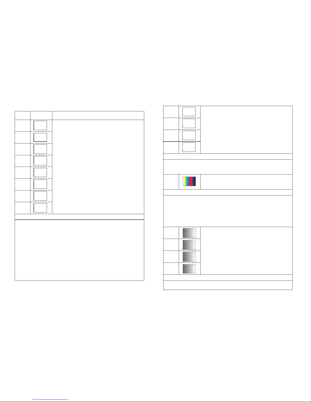
Purity pattern
Purity offers eight different full
field
patterns:
Black, White (100% Y)
Primary colors: Red, Green, Blue
Complementary colors: Magenta, Yellow, Cyan
P01: White
P02: Blue
P03: Red
P04: Magenta
P05: Green
P06: Cyan
P07: Yellow
P08: Black
Application
1. The red and green patterns are most frequently used for checking
color purity. The red pattern is selected only this color should be visible; the presence of any other color is an indication that color purity
needs adjustment.
2. The green pattern provides a purity check for three in-line tubes. In the
in-line tubes, the guns are in a horizontal position and the green gun is
located in the center.
3. The blue is the complementary colors are often used to check the
color performance.
4. The red are used to ensure that there is no interference between the
sound and chroma carrier. Furthermore the red pattern is used to adjust the longplay delay level to minimum
flicker.
5. In addition to the primary and complementary colors 100% white can
be selec
ted as well as black pattern with color burst to check.
8
P09
P10
P11
P12
GRAD
GRAD
GRAD
GRAD
Gradual pattern
Gradual transition of colors.
P09: Red
P10: Green
P11: Blue
P12: Gray
Application
This pattern is for brightness control and luminance writing current. And this
can overall the color performance, amplitude response/resolution and
linearity of chroma amplitude.
Color Bar
P13
Application
Comprises 8 vertical bars- White, Yellow, Cyan,
Green, Magenta, Red, Blue and Black
The white bar, to adjust the amplitude of the color difference signals with
respect to the luminance signal on the picture tube. The blue and green
guns can be switched off to allow the amplitude of the R-Y signal to be adjusted. This is done by ensuring that no difference in brightness is observed
between vertical bars
five
and six of the color bar and the horizontal reference bar. In a similar fashion, the amplitude of the B-Y demodulator can
be determined.
P14
P15
P16
P17
Grayscale
Full screen linear staircase signal with 8/16/32/64
identical steps from black to white
P14: 8 steps
P15: 16 steps
P16: 32 steps
P17: 64 steps
Application
This is used to locate faulty linearity of the video
amplifier
or greyscale set-
ting. Nonlinearities mainly result in a compression of the white level.
Page 5
9
P18
P19
P20
Application
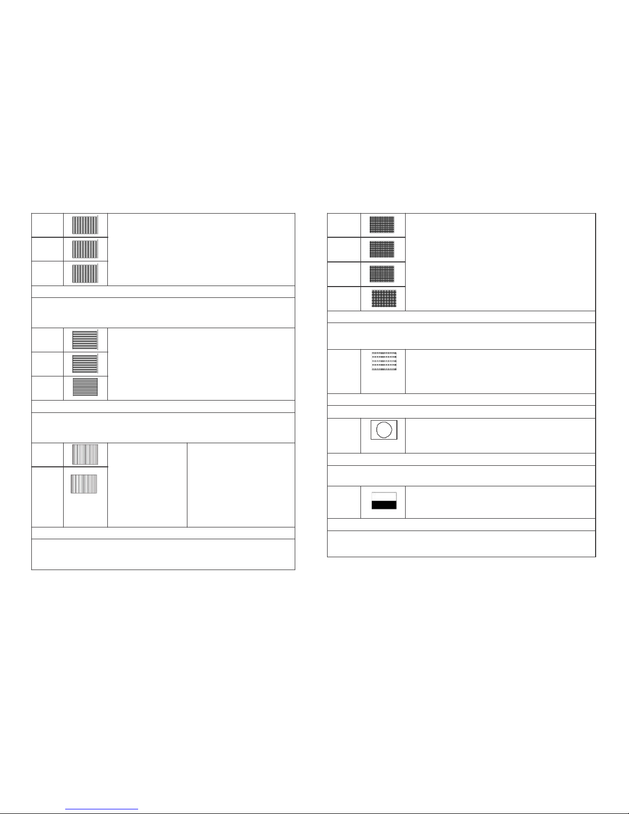
Black-White Vertical
Full screen linear vertical bar signal with black/white
intervals of 1/6/12 pixels.
P18: 1 pixel
P19: 6 pixels
P20: 12 pixels
This pattern serves for a quick check of color monitor’s horizontal band-
width and phase behavior of a video transmission. Also, verify video ampli-
fier
and color temperature.
Black-White Horizontal
P21
P22
P23
Application
Full screen linear Horizontal bar signal with black/
white intervals of 1/3/6 pixels.
P21: 1 pixel
P22: 3 pixels
P23: 6 pixels
This pattern serves for a quick check of color monitor’s vertical bandwidth
and phase behavior of a video transmission. Also, verify video amp
lifi
er and
color temperature.
P24
P25
Application
Multi-burst
Full screen
definition
pattern of frequencies 0.5, 1.0, 2.0, 4.0,
4.8, and 5.8 MHz for
625 line systems.
P24: Multi-burst 1
P25: Multi-burst 2
-Video bandwidth
-Check luminance
amplifier
in B/W
-Amplitude response/ resolu-
tion
-Check resolution of monitors
and video recorders
-Measure the frequency am-
plitude
response
The pattern checks the bandwidth of the video or luminance
amplifier
in B/
W or CTVs as well as the resolution of monitors and video recorders. It can
also be used to check or measure the frequency amplitude response.
10
P26
P27
P28
P29
Grid
Full screen grid with black/white intervals of 1/3/6/12
pixels.
P26: 1 pixel
P27: 3 pixels
P28: 6 pixels
P29: 12 pixels
Application
This pattern is mainly used for checking and aligning dynamic and corner
convergence of TVs or monitors.
Running H
Full screen
filled
with lines of H characters, a new
P30
line of H will run from upper left corner and
fill
down
when a line is completed.
Application
This is the special test for test/video motion
verification
and refreshing rate.
Circle
P31
Application
Black circles on white background, 640x480 has 4 by
3 total 12 circles, 800x600 has 5 by 3 total 15 circles,
1024x768 has 6 by 4 total 24 circles,
It’s suited for checking the overall linearity and geometry of the screen of a
monitor or TV.
P32
Black/White Up/Down
Full screen
filled
with upper half of 100% white and
lower half of 100% black.
Application
This pattern is for brightness control and purity checking. Also, to do the
white setting and synchronization.
Page 6
11
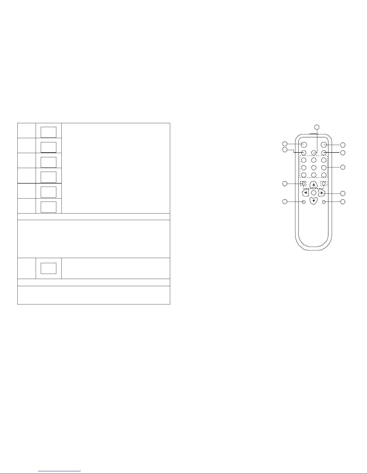
P33
CYP
P34
CYP
P35
CYP
P36
CYP
P37
CYP
P38
CYP
Cypress Patterns
Cypress
specifically
designed patterns.
P33: Greyscale
P34: 3 step Horizontal color bar
P35: SAMPTEbar
P36: CYP-4
P37: Britebox-1
P38: Britebox -2
Application
P33: This pattern is used for a
reflection
check or for adjusting the VCR
video demodulator to a symmetrical black and white jump or opposite.
P34: This pattern serves for a quick check of color monitor.
P35,P36: This pattern can be used to check the video handling capabilities
of most parts of a television system.
P37,P38: The wrong brightness setting on the monitor may cause other tests
such as Contrast, Focus and Beam Size to be invalid.
P39
HDCP
HDCP
-
Produce
Green/Blue horizontal bars with HDCP
verification
and data comparison on the upper
first
third area of
black background
Application
To test DVI and HDMI receivers with HDCP. All DVI and HDMI options, in-
cluding analyzer options, support HDCP production keys if the HDCP option
is installed.
12
6. Remote Control
4
1. Switch to P39 HDCP
2. Turn on/off AUTO pattern random-cycling
1
3. Color Space Selection:
RGB 4:4:4
3
HDCP
COLOR SPACE
AUTO
2
AUDIO HDMI/DVI
5
YUV 4:4:4
YUV 4:2:2
4. Audio Output Selection:
VGA SVGA XGA
SXGA UXGA 1080i
6
External L/R
External Optical
Internal Shinewave
5. HDMI/DVI Output Selection
6. Quick TIMING Selection:
VGA - T01 640x480-60
SVGA - T06 800x600-60
XGA - T10 1024x768-60
SXGA - T16 1280x1024-60
UXGA - T19 1600x1200-60
1080i - T27 1920x1080i-59
480p - T23 720x480p-59
720p - T25 1280x720p-59
1080p - T29 1920x1080p-59
7. Sampling Rate (-)
Sampling Rate (+)
192 KHz
96 KHz
48 KHz
44K1Hz
32 KHz
8. [pqtu]
UP/DOWN: TIMING (+) (-)
RIGHT/LEFT: PATTERN (+) (-)
9. A/V Mute ON
10. A/V Mute OFF
480p
SAMPLING
RATE -
7
P-
AV MUTE
ENABLE
9
720p
T+
OK
T-
CR-35
1080p
SAMPLING
RATE +
P+
8
AV MUTE
DISABLE
10
Page 7
13
7. RS232 Remote Control Application
7.1 Main Window
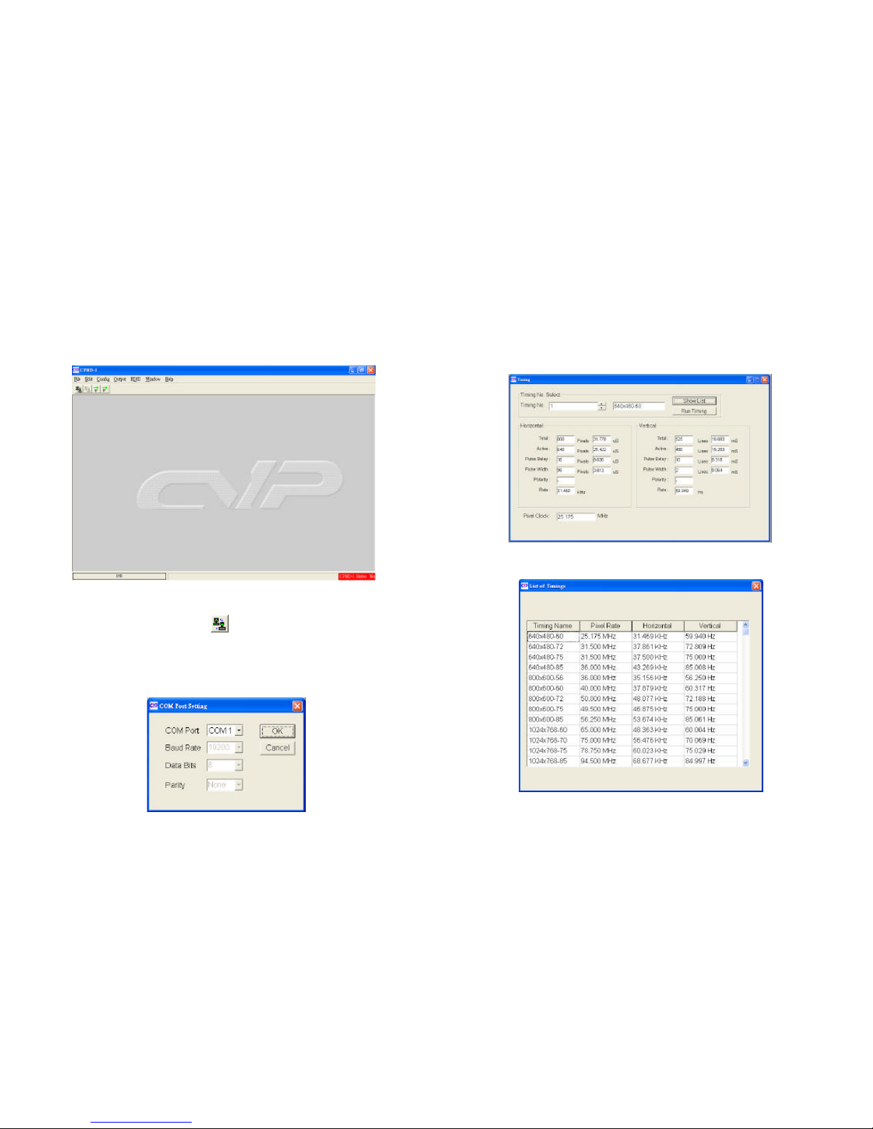
Double-click the executable exe file to launc h the application, the main
window will show up.
IMPORTANT: When the right hand bottom shows warning message ‘HDMIGEN
Status: Not Exit, clicking the Connect button to link to the unit.
7.2 Select COM port to control
Click and select the [COM port] from [Config] option of the tool
bar to launch the Program window. There are 8 different COM ports ca n
choose. After the port been selected click [OK] to
confirm
the control port.
14
7.3 Switch TIMING
Click and select the [Timing] from [Output] option of the tool bar to launch
the Program window.
Click [Show List] to display each timing’s Horizontal/Vertical/Pixel Clock.
Click [Run Timing] button to start the output of selected timing.
List of Timings
Page 8
15
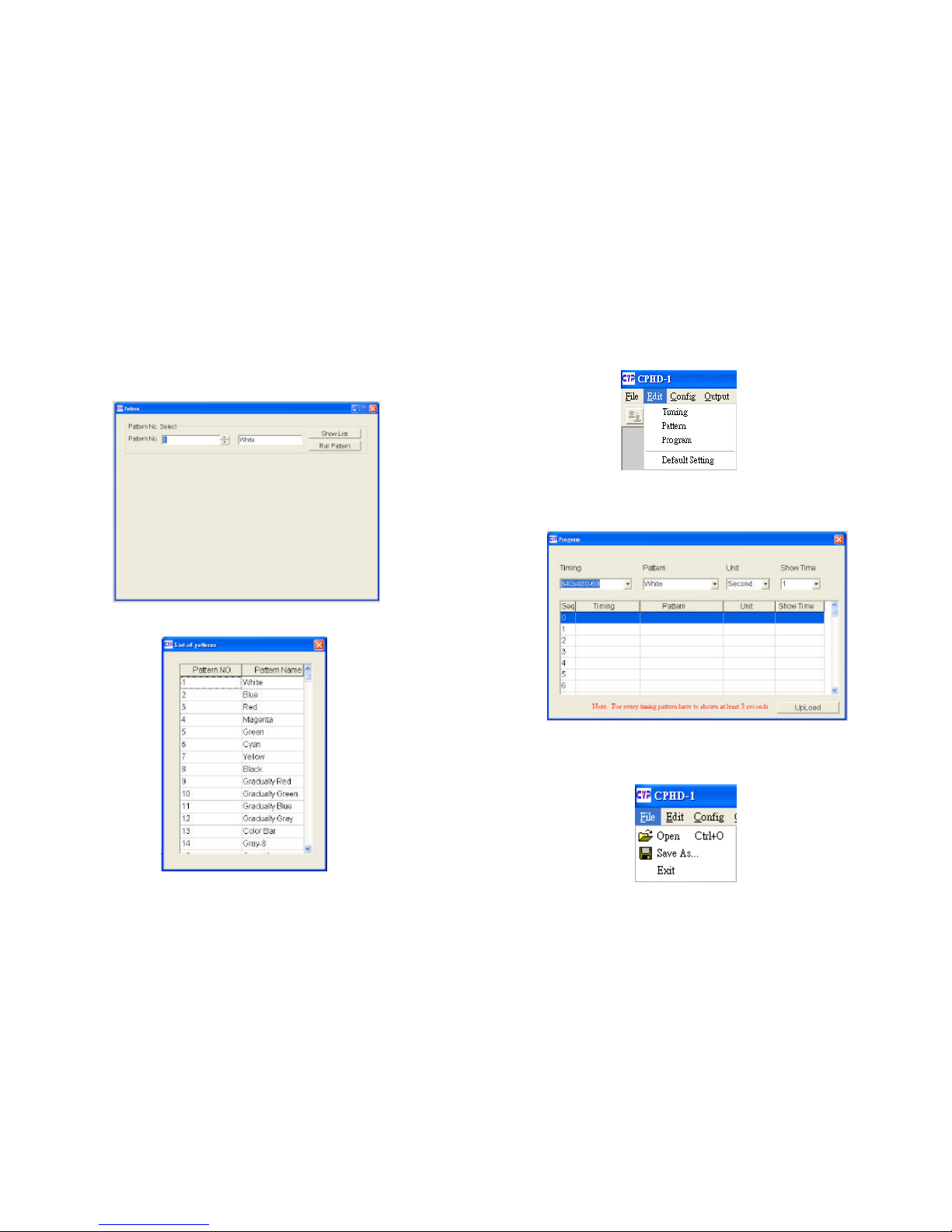
7.4 Switch PATTERN
Click and select the [Pattern] from [Output] option of the tool bar to launch
the Program window.
Click [Show List] to select output pattern and then click [Run Pattern] button
to start the output of selected pattern.
List of Patterns
16
7.5 Programming TIMING/PATTERN
Click and select the [Program] from [Edit] option of the tool bar to launch the
Program window.
Program the desired sequenc e of timing/pattern/unit/sho w time, then click
[Upload] to send the program to the unit.
IMPORTANT: For every timing pattern have to shown at least 3 seconds.
Click and select the [Save as] from [File] option of the tool bar to save your
settings.
Click the [Open] from [File] option of the tool bar to load the saved data.
Page 9
17
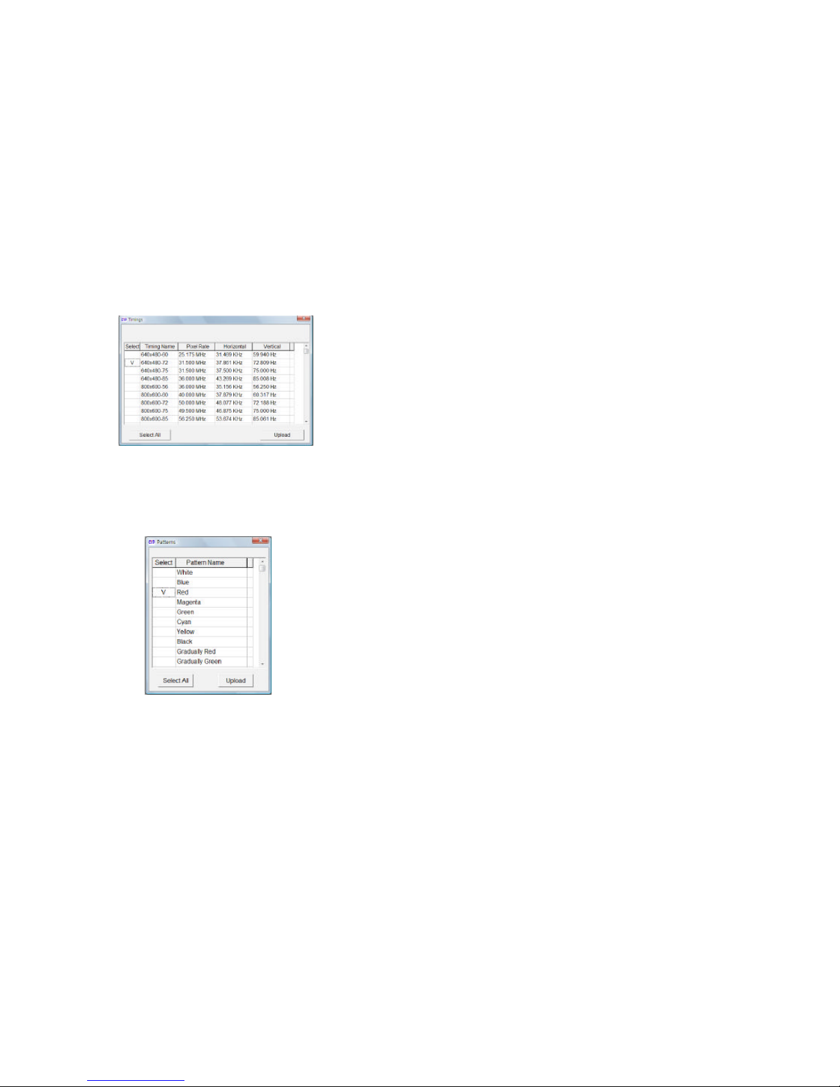
Click and select the [Timing] from [Edit] option of the tool bar to launch the
Program window.
Program the desired timings, and then click [Upload] to send the program to
the unit.
Click and select the [Pattern] from [Edit] option of the tool bar to launch the
Program window.
Program the desired patterns and then click [Upload] to send the program to
the unit.
Click and select the [Default Setting] from [Edit] option of the tool bar to reset
the unit to factory setting.
20
7.6 EDID
7.6.1 Read EDID
Click and select the [Read EDID] from [EDID ] option o f
the tool bar t o read out the EDID fro m the display source (e.g.
LCD TV). Meanwhile, click and select the [Save as] from [File]
option of the tool bar to save the EDID information to the
computer i n .bi n format (e.g. to save as thi s file format
“cypress.bin”).
7.6.2 Memory of EDID
When click and select the [Memory] from [EDID ] to read out the
data, but the user may not know the data information that read
out from the source. The user can use “Explore Semiconductor EDID
Editor” to read out the EDID information.
From “Explore Semiconductor EDID Editor”, click the [Open] from [File]
option of the tool bar to read out the EDID data.
7.6.3 Upload EDID
Click the [Open] from [File] option of the tool bar to load the saved
data (e.g. cypress.bin).
Click and select the [Upload EDID] from [EDID] option of the tool bar
to write the EDID to the unit.
INPORTANT: After upload EDID to the unit, don’t operation this
unit before write EDID to the displa y unit. Otherwise , the EDID data
will lose due to the memory size problem.
7.6.4 Write EDID
Click and select the [Write EDID] from [EDID] option of the tool bar
to write the EDID to the display unit.
 Loading...