

Spatz DXS-8, DXS-44, DXS-48, DXS84 Installation Instructions Manual

DXS-8 Matrix switch
applies to DXS-44, DXS-48, DXS84 and DXS-8
Installation instructions & technical manual
Congratulations! You purchased a powerful DVI digital matrix switch, capabable of switching up to 8 DVI signal
sources to up to 8 displaying devices like beamers, LCD monitors or other displaying units.
This manual will describe the installation procedure and give operating instructions. The explanations will help
you to understand the usage of the unit and give you all necessary informations to combine the DSX matrices
with your existing environment.
Please read this manual carefully. It will contain necessary information you will need for
safe and secure operation of the unit!
©2008 SPATZ All rights reserved.

1
OVERVIEW ABOUT FEATURES ........................................................................................................ 4
2 SETUP AND CABELING INSTRUCTIONS ......................................................................................... 5
2.1 UNPACKING ...................................................................................................................................... 5
2.2 PACKING LIST.................................................................................................................................... 5
2.3 OPERATION LOCATION REQUIREMENTS ..................................................................................................... 5
2.4 SETUP AND MOUNTING ......................................................................................................................... 5
2.5 ELECTRICAL CONNECTIONS ................................................................................................................... 5
2.5.1 mains connection ..................................................................................................................... 5
2.5.2 Attaching DVI video sources ..................................................................................................... 6
2.5.3 Attaching DVI displaying devices ............................................................................................... 6
2.5.4 RS232 connection .................................................................................................................... 6
2.5.5 TCP/IP connection ................................................................................................................... 6
2.5.6 Checking your cabeling ............................................................................................................. 8
3 OPERATING INSTRUCTIONS .......................................................................................................... 9
3.1 POWERING ON/OFF, STANDBY-OPERATION ................................................................................................ 9
3.2 OUTLINE OF OPERATION ....................................................................................................................... 9
3.3 SET UP VIDEO CONNECTIONS BETWEEN INPUTS AND OUTPUTS ......................................................................... 9
3.3.1 Making a connection ................................................................................................................ 9
3.3.2 Modifying or breaking an existing connection ............................................................................. 9
3.4 SAVE AND RECALL OF PRESETS ............................................................................................................. 10
3.4.1 Saving a preset ...................................................................................................................... 10
3.4.2 Recalling a preset setup ......................................................................................................... 10
3.5 MENU FUNCTIONS ............................................................................................................................ 11
3.5.1 Menu system ......................................................................................................................... 11
3.5.2 Menu tree ............................................................................................................................. 12
3.6 CONSOLE AND TELNET ACCESS ........................................................................................................... 13
3.6.1 Introduction to Console/Telnet ................................................................................................ 13
3.6.2 Console command description ................................................................................................. 13
3.6.2.1 edid_clear ............................................................................................................................................. 13
3.6.2.2 edid_list ................................................................................................................................................ 13
3.6.2.3 edid_mode ............................................................................................................................................ 14
3.6.2.4 edid_read ............................................................................................................................................. 14
3.6.2.5 edid_write ............................................................................................................................................ 15
3.6.2.6 exit ....................................................................................................................................................... 16
3.6.2.7 gettime ................................................................................................................................................. 16
3.6.2.8 help ...................................................................................................................................................... 16
3.6.2.9 ifstat ..................................................................................................................................................... 16
3.6.2.10 ip_setadr ........................................................................................................................................... 17
3.6.2.11 Ping .................................................................................................................................................. 17
3.6.2.12 pre_clear........................................................................................................................................... 18
3.6.2.13 pre_load ........................................................................................................................................... 18
3.6.2.14 pre_save ........................................................................................................................................... 18
3.6.2.15 reboot ............................................................................................................................................... 19
3.6.2.16 settime ............................................................................................................................................. 19
3.6.2.17 switch ............................................................................................................................................... 19
3.6.2.18 sys_addusr ........................................................................................................................................ 20
3.6.2.19 sys_delusr ......................................................................................................................................... 20
3.6.2.20 sys_fan ............................................................................................................................................. 20
3.6.2.21 sys_temp .......................................................................................................................................... 21
3.6.2.22 www_lang ......................................................................................................................................... 21
3.7 WEBSERVER ................................................................................................................................... 22
4 SAFETY REQUIREMENTS .............................................................................................................. 23
5 ELECTROMAGENTIC COMPATIBILITY (EMC) ............................................................................... 23
6 MAINTENANCE, REPAIR AND CLEANING ..................................................................................... 23
6.1 MAINTENANCE AND REPAIR ................................................................................................................. 23
CLEANING THE UNIT ............................................................................................................................. 23
6.2 ........................................................................................................................................................ 23

7
TECHNICAL MANUAL .................................................................................................................... 24
7.1 DVI ROUTING ................................................................................................................................. 24
7.2 EDID HANDLING ............................................................................................................................. 24
7.3 LABELS AND SYMBOLS ....................................................................................................................... 26
7.3.1 Markings on the faceplates ..................................................................................................... 26
8 TECHNICAL DATA ......................................................................................................................... 28
8.1 DXS-XX ....................................................................................................................................... 28
8.1.1 Mechanical data..................................................................................................................... 28
8.1.2 Electrical data ........................................................................................................................ 28
8.1.3 Approvals .............................................................................................................................. 28
8.1.4 Supported input signals .......................................................................................................... 29
8.1.5 “RS232” connector ................................................................................................................. 29
8.1.6 “TCP/IP“ connector ................................................................................................................ 29
8.2 ENVIRONMENTAL CONDITIONS ............................................................................................................. 30
8.2.1 Storage conditions ................................................................................................................. 30
8.2.2 Operation confitions ............................................................................................................... 30
9 BILL OF MATERIALS ..................................................................................................................... 31
1 Overview about features
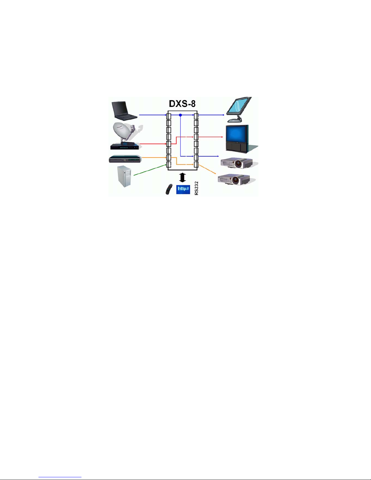
DXS-XX is a pure digital crosspoint switch (resp. matrix switch) for digital DVI video signals. It simultaniously
connects up to eight DVI sources to up to eight displaying devices. For each video source, you can either use a
“point-to-point” mode (where you connect exactly one source to exacly one displaying device) or a “point-tomultipoint” configuration, where the video signal of one input is distributed to several displaying devices.
Figure 1: typical application of DXS-XX
You can operate the DXS-XX by:
• manually using the front switches (buttons)
• remotely using RS-232 control
• remotely using an (optional) infrared remote control (not included)
• remotely using the build-in webserver (and your preferred internet browser)
• remotely using a telnet console
The DXS-XX has a blue character display in the frontside faceplate, which normally shows the actual swicthing
state, i.e. the current connections between the inputs and outputs. When operated remotely using the web interface, the current switching state of the matrix is displayed graphically, with console control (RS-232 or telnet),
you can query the switching state using a command language.
When changing DVI connections between video sources and displaying devices, it is not only necessary to switch
the video connections/informations, but also to properly handle so called EDID-Information, which is mandatory
in the DVI standards. DXS-XX will manage this automatically, according your setup configuration.

2 Setup and cabeling instructions
2.1 Unpacking
Please take DXS-XX out of the shipping box, take away plastic shock protection and transportation bag. Strip of
front panel protection tape, starting at one corner of the front panel. Unpack power cord and all other material
supplied with the shipment, and keep it ready for use.
2.2 Packing list
Please check shipment for all parts, listed in the packing list below:
• one DXS-XX-unit (size 435,0x260,0x44,0 mm)
• two side protection covers (foam, white)
• one power cord, length 2m
• one serial RS-232 cable, length 2m, one side DSUB9 male, other side DSUB9 female. Connected 1:1
• four black rubber stickers, to be attached, when unit is operated desktop
• optional (if ordered): one infrared remote control
• two 19-inch rack mount brackets, one with additional center cutout to support ventilation. This bag will
also have eight screws (black, M4x5mm).
• one operation manual (this document)
2.3 Operation location requirements
The DXS-XX has an IP 40 degree of protection against dust and humidity (according to IEC529).
You have to ensure a mounting or operation location, where no danger of entering fluids will exist.
Furthermore you must ensure compliance with the specified environment conditions (see chapter 8.2), especiually temperature and relative humidity.
2.4 Setup and mounting
You can operate DXS-XX „desktop“ on a shelf or tabletop, by sticking the four rubber stickers to each corner of
the bottom of the DXS-XX unit. With that stickers, small roughness of your table is compensated and the unit will
not slide away on flat surfaces.
Alternatively, you can mount the DXS-XX into a 19-inch rack, using the brackets supplied. The mounting of the
brackets is simple, you just need a screwdriver (size PH2). Start on the left hand side of the unit (front is the side
with the buttons, top is top when reading the front panel tags correctly) and unmount the two front and the two
middle screws completely. Take the one bracket with the center cutout and attach it to the left hand side of DXSXX, using the longer M4x5 screews contained in the bracket’s bag. After that, the ventilation cutout of the DXSXX chassis should not be blocked significantly by the newly attached bracked. Repeat procedure on the right
hand side, using the remaining bracket.
When operated desktop or rack-mount, please ensure that nothing will cover the ventilation cutouts on the lefthand side of the unit.
2.5 Electrical connections
2.5.1 mains connection
Please attach mains cord (supplied with shipment) into the IEC-320 connector of the DXS-XX. This connector is
located on the back side of the unit. Now plug the mains plug into the wall outlet of your installation.
The DXS-XX has no power switch, it will immediately start operation when plugged into a “hot” wall outlet. The
unit will boot and ready for operation after 10..15 seconds.
The blue LED of the power button (caption: O/I, rightmost front button) will be permanentely on, when unit is
powered and active. Each time, the main power fails and returns, the DXS-XX will return to the ACTIVE state!
As the unit has no main power switch, it will be ON after attaching the unit to a powered
wall outlet. To have the DXS-XX de-energised, please detach mains power cable!
Never expose any cables to mechanical stress like strong bending or pull. This can damage
cables and impact security!
2.5.2 Attaching DVI video sources
Next step in setup procedure is attaching video sources.
To avoid damages is DXS-XX and your existing video sources, all connections between components are to be done when ALL units are powered off. Now ensure that you have powered
off all video sources and the DXS-XX.
Now connect your DVI video sources to DXS-XX, using your DVI-D-video cables (not with the shipment), one
after another. All inputs of DXS-XX will be labeled with “Input 1” to “Input 8”. You are free to use any input you
like for a specific source, all inputs are electrically identical.
It is a good idea to denote all input connections, i.e. which source goes to which input number.
You can use any DVI-D cable, with high quality cable you can have your video source up to 35m away from the
DXS-XX. Each input has a signal equalizer that refreshes the signal to stand ard levels.
If you are having your DXS-XX licensed only with four inputs (i.e. VSD44 or VSD48), the inputs labeled “Input 5”
to “Input 8” are out of functionality and should not be used, i.e. you can not route signals from these inputs to
any output. But there is not problem or damage, if you attach video sources there by accident.
Mechanically fix the connctions by using the screws of the male DVI connector. This will
ensure reliability of the system.
2.5.3 Attaching DVI displaying devices
Now connect your displaying devices (i.e. monitors, LCDs or beamers) to the outputs of the DXS-XX, using your
DVI-D cables (not with the shipment). All outputs of the unit are labeled “Output 1” to “Output 8”. Your are free
to use any of the available outputs for your devices, all are electrically identical.
Complete your written notes by denoting the output assignement, i.e. which output goes to which of your displaying devices.
Use no DVI cables longer than 5 m as output cables when using maximum video resolutions like 1600x1200 Pixels.
If your are having a DXS-XX licensed only to four outputs (i.e. DXS-44 or DXS-84), only “Output 1” to “Output 4”
will be active. All other outputs will carry no active video signals, but provide signal levels according to DVI standard.
Mechanically fix the connctions by using the screws of the male DVI connector. This will
ensure reliability of the system.
2.5.4 RS232 connection
If you intend to control the DXS-XX matrix switch by a PC or Laptop using the RS-232 serial interface, please
connect the serial cord supplied to the DSUB9F-connector at the back of DXS-XX, to the connector labeled “RS232”. The other end of the cable should be connected to the serial interface of your PC/Laptop. If your equipment does not have a serial interface or connector, you can use either control by network/TCP or using a
USB/RS-232 converter dongle available in some shops. You can find pin connection diagram and configuration
data of the serial interface in section 8.1.5 of this document.
2.5.5 TCP/IP connection
Using a TCP/IP network connection, you can control DXS-XX remotely either using a web interface or using a
telnet console session.
If you intend to use this kind of control, please connect a standard network cable (for 100MBit/s CAT5 or higher)
to the port labeled “TCP/IP” at the rear of the unit and your network. The unit will support 10MBit/s and
100MBit/s TCP/IP networks, but does not have a so called “Auto-MDX”-mode, i.e. when you like to connect it
directly to a PC’s network interface, you have to use a “crossed” network cable or your PC’s network adaptor
must be capable of Auto-MDX.

2.5.6 Checking your cabeling
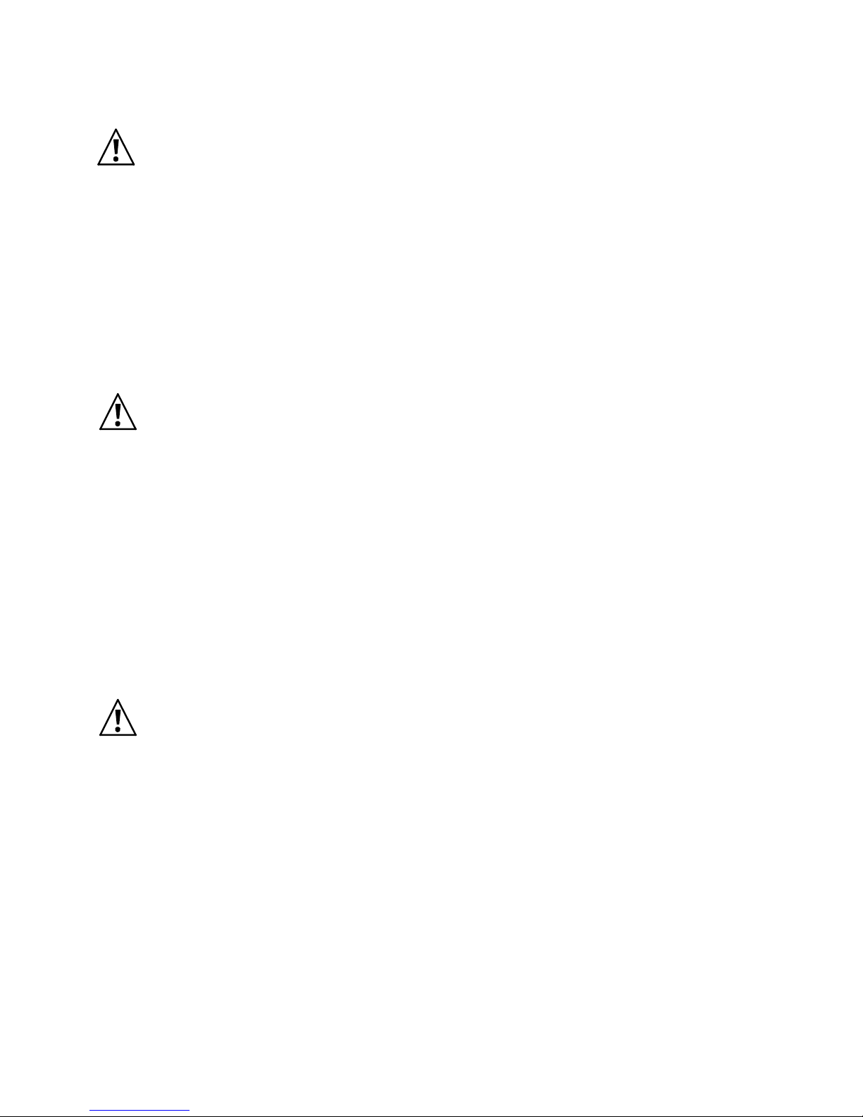
After doing all connections, you overall system (containing the DXS-XX) should look like this:
Figure 2: DXS-XX cabeling

3 Operating instructions
3.1 Powering on/off, Standby-operation
When DXS-XX is connected to a hot wall socket, it will start and boot automatically. All button LEDs will flash for
a short period of time and the text display will show a short welcome message (from the bootloader). After that,
the unit trys to reach a TCP/IP network (if cable connected).
After 10 seconds max., the unit is up and ready for operation. The text display will switch to a “status display”
mode (see figure 3). You can read all active routing connections from that status display. All outputs available are
written in the top row, starting with “OUT:”. The lower row displays the number of the input connected to the
output above. A minus sign says, that the output has NO connection to any input. Reading a number gives the
number of the input channel, that is actually connected to the output.
Figure 4: Routing status display (example)
The example in figure 5 reads:
• Outputs # 1,4 and 6 are off
• Output #2 shows video connected to input #6
• Output #3 shows video connected to input #4
• Output #5 shows video connected to input #5
• Output #7 shows video connected to input #3
• Output #8 shows video connected to input #1
By pressing the “O/I”-button on froint panel longer than 3 seconds, the DXS-XX will quit active mode and go to a
standby mode of operation. All active connctions break and the unit will turn off most of its internal functions.
If the unit is in standby, you can activate it by pressing the “O/I”-button longer than about 1 second. Then, all
previous routing connections are re-established (both video and EDID-connections).
3.2 Outline of operation
As mentioned shortly in chapter 1, the DXS-XX can be operated by different methods. These methods differ in
complexity and level of control, so rookies and professional users will find their appropriate control meth od.
To ease handling of the DXS-XX and have a quick start, let’s outline the next sections:
• make and break video routing connections
• save and recall setups scenarions with “presets”
• control system’s menu tree
• control system’s features through remote interfaces like console or web interface
3.3 Set up video connections between inputs and outputs
3.3.1 Making a connection
First, select the output number of the connection you intend to make by pressing one of the numeric buttons “1”
to “8” (resp. „1“ to „4“, if you only licensed 4 Outputs). Now, the LED of the selected output will flash slowly. And
the cursor in the text display will flashg the number of the selected output channel.
Now pressing one of the numeric buttons “1” to “8” (resp. “1” to “4”, if you licensed only 4 inputs) will make the
connection to the selected input number. The former flashing LED will blank and the status text display will show
the newly established connection.
3.3.2 Modifying or breaking an existing connection
An existing connection can be modified by re-establisting a new connection/routing, just like described in the
previous section. If you intend to break an existing connection, just press the number of the output you want to
turn off (break connection), after the LED light flashing, press the “P”-button. This will break the connection and

turn off the LED. The text diplay will show a minus sign under the selected output number, to show the “off”connection.
3.4 Save and recall of presets
You can save or recall a routing setup any time you like. By saving a preset, you can preserve a complex setup
for later use. By recalling a setup, you can switch several channels synchronously.
3.4.1 Saving a preset
For preserving the routing state of DXS-XX, i.e. which inputs are connected to which outputs, DXS-XX system
offers eight so called “presets”. These presets are non-volatile, i.e. even after power-loss you can restore your
system routing, if you have saved it to a preset bank before.
To save a setup as preset, make all connections you like to do. Then press the “P”-button (“P” like preset) longer
than a second. The text displays then switches to the “PRE-SAVE” mode, like in figure 6.
Figure 7: Saving a preset
The display now shows eight available preset banks (storage locations) in the top row, the lower row shows the
usage status of the bank. A carret says, that the preset bank is already used, but can be overwritten, a minus
sign says, the preset bank is free.
The cursor and the eight LEDs (on the eight numeric buttons) invite you to select the preset bank you desire, by
pressing the appropriate numeric button. After sucessfully selecting a preset bank, the text display will return to
the status display of figure 8 and all flashing LEDs will stop flashing.
If you like to cancel saving instead, just press the “P” button instead of one of the numeric buttons. Then preset
save dialog will be canceled and text display will return to standard status display of figure 9.
Attention:
• Only the actual routing information will be stored into a preset bank. No EDID-content will be saved (and
recalled later) using the preset functions!
3.4.2 Recalling a preset setup
To load (recall) a saved preset , just press the „P“-button shortly. The text display will switch to a “PRE-LOAD”
mode, as printed in figure 10.
Figure 11: Loading a preset
Like when saving (see section 3.4.1), the top row will display all eight preset banks, the lower row will show all
used banks with carets, unused free banks are shown as minus sign.
All LEDs of those numeric buttons will flash slowly, that represent used banks, i.e. those banks that can be recalled. Just choose the preset number desired by pressing the numeric button on the front panel. The load process is immediate, i.e the video routing is modified immediately according to the saved routing configurations.
After successful loading, the text display will return to status display mode like in figure 12.
If you like to cancel the recall process, just press “P” button instead of one of the numeric buttons, then the text
display will return to standard status display and LEDs will stop flashing.
 Loading...