

Page 1
Operating Instructions
S-Thermatik NEO
Page 2
PREFACE / QUALITY PHILOSOPHY
You have decided in favour of a SPARTHERM fireplace insert accessory - thank you very much for your confidence in our company.
In a world of excess and mass production, our company stands for the values expressed by our owner, Gerhard Manfred Rokossa:
"High technical quality combined with contemporary design and service to the satisfaction of our customers, so they will recommend us to others".
Together with our specialist retail partners, we offer you first-class products that will touch your customers emotionally, and will inspire feelings such as a feeling of
security, safety and comfort. To achieve this, we recommend that you read the operating instructions carefully in order to get a quick and comprehensive overview
of your decorative fireplace.
In addition to the information on operation, this manual also contains important care and operating instructions for your safety as well as preserving the value of your
accessory and provides valuable tips and tricks.
For further enquiries, please contact your specialist dealer.
We hope you enjoy your new stove.
Your Spartherm team
G.M. Rokossa
Page 3

GB
GB 3
1. General information 4
1.1 Information on installation 4
1.2 Accessories 4
1.3 Functional description of S-Thermatik NEO 5
2. Safety notes 6
3. Menu structure and display 6
3.1 Menu structure 6
3.2 Main menu 7
3.3 General operation of the display 7
4. Statistics 8
5. User menu 8
6. Self-test: 10
7. Power failure 11
8. Service menu 11
9. Closed-loop control characteristics 12
10. App 13
11. Notes for stoves: 14
12. Guide 15
13. General warranty conditions 16
13.1 Area of application 16
13.2 General information 16
13.3 Warranty period 16
13.4 Warranty requirements 16
13.5 Exclusions from the warrant y 16
13.6 Elimination of defects / repair 17
13.7 Extension to the warranty period 17
13.8 Spare parts 17
13.9 Liability 17
13.10 Closing remarks 17
14. EU Declaration of Conformity 18
CONTENTS
Page 4

GB 4
1.1 INFORMATION ON INSTALLATION
Please consult your district master chimney sweep before assembling and
installing your fireplace. He will advise you on building regulations, will
check the suitability of your chimney, will commission your fireplace insert
and will issue the operating licence for your fire area.
When installing and operating the fireplace insert and connecting it to the
chimney, make sure that you comply with the national and European standards, the country-specific and local directives and regulations as well as the
fire regulations for your federal state (in Germany only) and the Technical
Rules of the Tiled Stove and Hot Air Heating System Trade (TROL).
All work on the electrical installation may only be performed by an authorised specialist company. All equipment must be switched off at the main
switch before performing work on it.
1.2 ACCESSORIES
If needed, all conduits can be extended using normal copper cable, but this
does apply to the cable on the flue gas temperature sensor. Here, a
special compensating line MUST be used.
• 5m flue gas sensor extension cable (Item No. 1013221)
• 10m extension cable for flue gas sensor (type no. 1013222)
With appliances that circulate water, if the recirculating pump is to be
controlled by the S-Thermatik NEO, at least two PT 1000 sensors should
be ordered at the same time. This is the only way of ensuring that the
"Differential temperature" function can be implemented together with the
S-Thermatik NEO.
• Temperature sensor PT1000 (part no. 1013765)
Length 3 metres, incl. immersion sleeve with a G1/2" external thread
1. GENERAL INFORMATION
You have decided in favour of a Spartherm fireplace insert accessory - thank
you for your confidence in our company.
This manual provides you with information about operation and troubleshooting for your combustion control. Details on installation and for service
purposes can be found in the "S-Thermatik NEO installation and service
instructions".
Information for setting the parameters of the control system can be found in
the accompanying supplementary sheet "Details of the S-Thermatik NEO".
Please keep this supplementary information and the operating manual in a
safe place.
Important information and safety instructions are printed in bold always comply with these points.
Before using the appliance, please read the entire operating manual.
The combustion control system is pre-set to the nominal thermal output
of the delivered fireplace insert. Information concerning the nominal heat
output and the wood feed quantity can be found in the operating manual of
the fireplace insert.
To maintain your control system, keep the door contact clean and ensure
that the combustion air channel remains clean and unobstructed. From time
to time, check here whether the permanent magnet is attached to the bottom of the door frame and that it is still undamaged.
Page 5
GB
GB 5
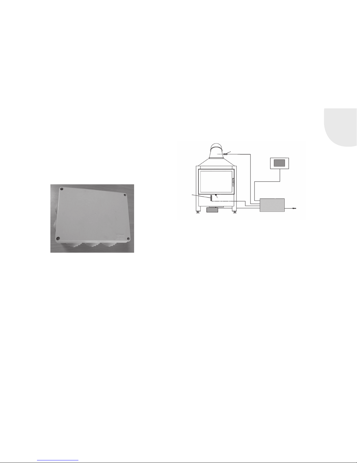
Door contact
switch
Temperature sensor
Display
Control
230V AC
Mains connection
Air adjustment
lever
Actuator
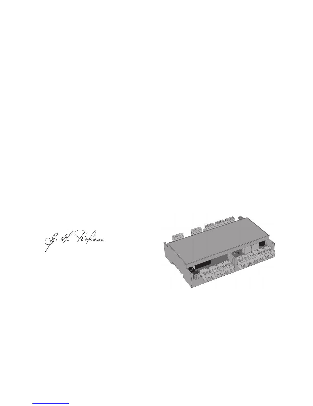
1.3 FUNCTIONAL DESCRIPTION OF S-THERMATIK NEO
The basic configuration of the S-Thermatik NEO combustion control system
consists of the control unit, the display, a flue gas temperature sensor, an
actuator motor and a door contact switch. It is only suitable for fire areas
that burn split logs.
The combustion control system is activated when the firebox door is opened
and is awakened from Standby mode. Depending on the prevailing flue gas
temperature, the control system adjusts the motor using the air slider until
the correct quantity of combustion air is directed into the appliance. The
time for adding fuel is displayed with a visual as well as an audible signal.
The control system remains active until the flue gas temperature has
dropped to about 50°C and then it returns to Standby mode.
In the event of a power failure, the air slider automatically moves into a
position in which the fire area can continue to be operated. Until power is
restored, or until the fire is extinguished, no further interventions or measures are required.
If the control system housing of the NEO is to be protected in a special manner, a dust protection box measuring 210 x 160 x 80 mm can be obtained
in which the control system can be installed.
ATTENTION: The cable housings (see 3.3) must be removed, otherwise the
control system will not fit inside.
• Dust protection box for S-Thermatik NEO (part no. 1013792)
Page 6

GB 6
2. SAFETY NOTES
• The S-Thermatik NEO combustion control may only be used in combination with a wood-fired fireplace insert.
• Only fire areas which are ordered with this combustion control system
and that are appropriately prepared from the factory can be combined
with the S-Thermatik NEO.
• The combustion control system cannot be retrofitted!
• The maximum ambient temperature for the electrical components is
50°C. Measures must be taken by the customer to ensure that this
temperature is not exceeded.
• The total electrical installation of the individual components may only be
conducted by an authorised specialist company.
• All electrical installations are to be carried out as per the VDE regulations (e.g. VDE 0105, VDE 0116, VDE 0100, etc.) and the technical
connection conditions of the local power company.
• All equipment must be switched off at the main switch before performing
work on it.
• The cables must be laid so as to allow maintenance work to be performed and the individual components of the S-Thermatik NEO to be
replaced without any problems.
• Building moisture and condensation are to be avoided as these can
result in corrosion and failure of the electrical components.
• The connecting cable of the flue gas temperature sensor can only be
extended with a special compensation cable!
• The function of the combustion control system may be checked at any
time with the air control lever. Every time the firebox door is opened,
the air control lever must move to the right to the "combustion
air fully open" position!
• The specified factory settings which are required for the safe operation
of the combustion control may not be changed.
• The installed wires on the fireplace insert must not be pulled. Outside
the fireplace insert, these must be installed so that no tensile forces and
no compression, chafing or shearing points are created.
3. MENU STRUCTURE AND DISPLAY
3.1 MENU STRUCTURE
To keep things simple, the menu is divided into just three sections:
• Statistics of the last 99 burnups
• User menu
• Service menu (password-protected)
Regardless of where you happen to be in the menu, using the Menu button
at the bottom right, you can always return straight to the menu selection.
In the same way, pressing the Home key at the bottom left returns you
immediately to the main menu.
Layout of the menu:
Home (main menu)
Statistics User menu Service menu
Overview of the last 99 burnups SESAM *
System set-up
S-USI II **
Display
Sound
Auto / Manual
Language
Deactivating the door
System information
Selecting the fireplace insert
Parameters
Relay Menu
Doorswitch Menu
Motor Menu
Overview
Test
Factory setting
Saving user data
Loading user data
System settings
* only appears if the corresponding function was selected in the Relay
menu
** Connection option for an S-USI II differential pressure monitor, available
from 2018
Page 7

GB
GB 7
3.2 MAIN MENU
1 Current status and error messages
2 Progress bar
3 Room temperature, air slider setting and flue gas temperature
4 Heating capacity levels (small / normal / big burnup)
The main menu provides information at a glance of the prevailing operating
mode of the control system. At this level, you can only click the heating
capacity levels via the flame icon and the Menu button.
The progress bar indicates the prevailing point in the combustion process.
Here is a key to the 6 points:
Standby / ignition / rising temperature / falling temperature / time to add
fuel (that is the small point) / glow phase
The flame symbol can be used to select a small / normal / big burnup. The
fire area then receives less or more combustion air respectively.
3.3 GENERAL OPERATION OF THE DISPLAY
There is a BACK button at the top left of each menu window to enable you
to go back one step in the operating process. If something is changed in a
window, the Save button appears at the top right.
Adding fresh fuel
POWER STAGES
Home
Menu
CURRENT TEMP
AIR SLIDER
EXHAUST TEMP.
4
1
2
3
CANCEL
Brightness
SAVE CHANGES
USER MENU
Auto brightness
Home
Menu
Page 8

GB 8
4. STATISTICS
This is where you will find the statistics for the last 99 combustion processes. These are always counted from one opening of the door to the next,
i.e. every single burnup is counted. In each case, the maximum temperature and the duration of the burnup are recorded. The statistics cannot be
deleted. If there are more than 99 burnups, the older data are overtyped.
5. USER MENU
The menu layout is broadly self-explanatory. Here is a sample image for
general operation:
1 BACK button
2 Name of the menu
3 Scroll keys
4 Function
5 Setting controller
6 Operating knobs
Sliders can be adjusted by fingertip control, or by holding and sliding the
round knob. The control knobs can be moved by touch, or by sliding them
gently to the left or right. If the knob is backlit in red, the selected function
is enabled.
Note: The active surface of the scroll keys is larger than shown on
the display. Scrolling is then also activated by touching beside the
grey surface.
CANCEL
Statistics
LAST COMBUSTION
Highest temperature
Highest temperature
Highest temperature
Duration
Duration
Duration
CANCEL
Sound
USER MENU
Signal transmitter active
Sound 2
Sound 1
Home Menu
1
2
3
4
5
6
Page 9

GB
GB 9
If settings have been changed, SAVE appears in red letters at the top right.
This pushbutton must be pressed otherwise the changes will not be made.
SESAM: Whenever this function is assigned to a relay in the Service menu,
this field appears at the top of the User menu. By touching this box, the
relay is activated for 3 seconds. This enables the Spartherm SESAM control
system to be activated, an electrical opening mechanism for fire doors. For
more details see Chapter 5.4.
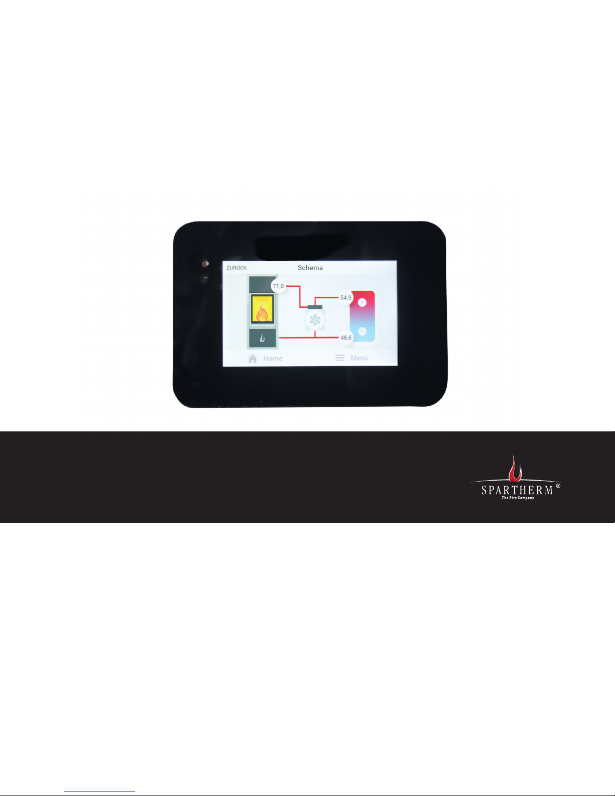
Diagram: Here, the hydraulic schematic and the switch status of the accumulator charge pump on water-circulating fireplace inserts can be illustrated. Whenever the pump relay on the NEO has engaged, the pump vane
wheel rotates on the display panel
If the PT1000 sensors are not connected, e.g. on air-circulating fireplace
inserts, no temperature values appear. Instead, dashes (- - -) appear on
the screen.
By touching the temperature boxes, you can select which sensor should be
displayed here.
S-USI II: When using a Spartherm S-USI II differential pressure monitor,
it can be connected to the S-Thermatik NEO using a special cable. The
displays on the housing of the S-USI II can be shown on the display unit of
the NEO.
The S-USI II will probably become available in the early part of 2018.
Display: Here, among other things, is the Screen Saver sub-menu. Here you
can choose the brightness level you wish to have for the screen saver. If you
choose several temperatures, these will be displayed at 7-second intervals.
If you pull the brightness controller all the way to the left, the display will
go dark. The screen saver switches on automatically about 2 minutes after
the most recent keystroke. The screen image reappears whenever you touch
the display unit.
Note: With water applications, it is advisable to display the temperature at the top in the buffer. This means that you can see immediately the level of progress of the loading of the buffer.
In addition, there is a "Cleaning the display" sub-menu. This switches off
the display for 2 minutes. During this time, it accepts no commands. This
means you can clean without altering any of the settings. For checking
purposes, a timer runs backwards and shows the remaining time.
Sound: Here the button acknowledgement sounds and the alarm sounds
can be selected. Also, the volume level can be adjusted. All sound events
can also be switched off here.
Operation auto/manual: Here you can switch form Automatic to Manual
mode. To do this, move the "auto/man" control knob to the right. Now a
position can be selected for the air slider and it can be sent off using the
SAVE button at the top right.
CANCEL
Schematic
Home
Menu
Page 10

GB 10
To return to Automatic mode, slide the control knob to the left again and
save it.
CAUTION: Operation of the fire area in Manual mode is at the user's
own risk! During a burnup, the air control lever must never be closed
to the point where an explosion might occur.
We urgently advise that you ONLY operate the control system IN
AUTOMATIC MODE.
Language: Here, you can select the menu language of your choice.
Available at the present time: GB - DE - NL - FR - IT - ES - PL - CZ - SE
Deactivating the door: Exactly as in the display (see above), the door
switch can be deactivated for 2 minutes. This can scale down the glow without the control system initiating a new burnup when the door is next opened.
System information: Here you will find details about the details of the
respective versions of software used.
6. SELF-TEST:
To check the control system and its function, it can help to run a self-test.
This provides an indication as to whether all components in the control
system are OK.
We advise running the self-test once a year at the start of the heating
season.
The self-test is carried out every time that the control system becomes
disconnected from mains power, once mains power has been restored. To
conduct this self-test, the fire area must be cold (flue gas temperature
below 50°C) and all fire doors must be closed.
1. Switch the combustion control off (pull out the power plug)
2. Switch the combustion control on again (insert the power plug)
3. The air control lever moves to the right, up to its 100% open limit stop.
With stoves, the function monitoring LED remains lit all the time.
4. Then the air control lever moves to the left towards 0%. The function
LED on stoves goes out at this point in time. The air control lever remains
fully left, against its limit stop.
5. "Standby" must appear on the display and realistic values must be displayed for room and flue gas temperature.
6. If the firebox door is now opened, the air control lever must move automatically to the right, up to its limit stop. The function LED remains lit
continuously. While the door is open, the function LED on stoves flashes
rapidly, about 2x per second. The display shows that the door is open.
7. If no fire is ignited 10 minutes after the door has been closed, the display shows "No ignition". The air slider is closed and the control system
reverts to Standby mode.
8. Any errors on the flue gas sensor or motor are displayed in clear text. On
stoves, the function LEDs then flash rapidly.
Page 11

GB
GB 11
8. SERVICE MENU
The Service menu is password-protected and the password is known only to
the stove fitter and/or the after-sales service.
A warning is issued about adjusting these settings if you do not have
the relevant professional knowledge.
Incorrect settings can cause very serious damage to equipment as
well as personal injury.
If the test has been successful up to this point, without failures or error
messages, then the control system and its external components are OK.
Note: The self-test only functions at flue gas temperatures of less
than 50°C. At higher temperatures, the lever only moves to the right.
After that, the control system resumes normal operation.
7. POWER FAILURE
The S-Thermatik NEO is equipped with a special function. Whenever there is
a power failure, the air slider automatically moves into a safe position (about
50-60%). In this position, the fire area cannot overheat, but it can continue
being operated manually. You can also allow the fire to be extinguished.
Until mains power is restored, no intervention by the operator is required. Do
not attempt to move the air control lever mechanically. This is not necessary.
This safety function on the NEO operates entirely without the need for maintenance, and it does not require any batteries or accumulators.
CANCEL
ADVANCE SETTINGS
Password request
Type the password key for service menu
Page 12

GB 12
• Following a cold start, if a temperature of at least 50°C is not reached
within 10 minutes of the door being opened, the air slider is closed and
the control system reports "No ignition".
• Whenever the fireplace insert threatens to overheat, this is
displayed and the air slider is restricted in order to reduce the
temperature. Once the temperature has dropped far enough, the
burnup is then continued with the declining closed-loop control
curve. During the next burnup, add less wood.
9. CLOSED-LOOP CONTROL
CHARACTERISTICS
This section explains a few of the closed-loop algorithms that govern operation of the control system.
• In the event of a power failure or failure of the flue gas sensor, the air
slider moves automatically into a safe position (approx. 50 - 60%). The
fire area can continue to be operated manually.
• On cold starts (exhaust temperature below 50°C), the first burnup always
takes place during the "powerful burnup" stage. During this time, the big
flame symbol is NOT displayed. With the ensuing burnup, the system
then switches to the preselected stage.
• The acoustic signal to add more fuel only sounds once, when the time
to add more fuel is reached for the first time. After that, this signal is
not repeated.
• In Manual mode, there is no progress bar, and no selectable heating
capacity. Whenever the door is opened, the air control lever moves to
100%, stays there for one minute, then returns to its manually set position. We urgently recommend that you only operate the fire area
in Automatic mode.
• If wood is not added at the time for adding more fuel, the glowing phase
commences a short while later. Here, by alternating the air slider positions, it is possible to change the declining combustion curve several
times. The air slider is not fully closed until the flue gas temperature
has dropped below 50°C and the control system has dropped back into
Standby mode. Up until that point, the air slider is never fully closed.
• Regardless of the flue gas temperature, whenever the door is opened,
the air slider first moves to its 100% position. After a stabilisation time,
it then moves to a position that suits the prevailing flue gas temperature,
as defined in the parameter settings.
Page 13

GB
GB 13
The data link only functions using Bluetooth. The module is integrated in
the control system. At any one time, it is only possible to connect one
mobile device to NEO. You cannot select a different device until Bluetooth is
switched off to the connected device or until the device leaves the Bluetooth
reception range.
A code for your S-Thermatik NEO can be defined in the Service menu /
System / Bluetooth. This can prevent unauthorised accesses or overlaps.
The factory setting is 0000.
10. A PP
For the S-Thermatik NEO there is an app for devices with an Android or an
IOS operating system. This app goes by the name of S-Thermatik NEO and
it can be downloaded from the Play Store or from iTunes.
To install this app you need to enable Bluetooth on your device, and you may
also need to permit "Installation from unknown sources".
NEO is operated by this app on your mobile device in the same way as via
the NEO display: the menus are identical.
Page 14

GB 14
11. NOTES FOR STOVES:
Stoves are usually supplied without a display The user obtains information
about the current status of the control system from a function monitoring
LED that is usually installed in the bottom flap of the stove.
The LED works in the following manner:
OFF: control system is in standby mode, fire area is off
ON: control system working in feedback control mode OR
is currently open, performing a self-test in the direc-
tion of 100%
SLOW FLASHING: The time for adding fuel has been reached
FAST FLASHING: The door is open, the appliance has overheated or an
external component is malfunctioning
During the slow flashing mode, the LEDs light up about 1 x per second, and
about 2 x per second in the fast flashing mode.
Even on control systems without a display it is possible to connect to the
appliance using the app and Bluetooth. The standard password for the Bluetooth connection is 0000.
On stoves, a mechanical Auto / Manual control knob is usually installed in
the lower section of the appliance. This should always be set to Auto.
Only then can the S-Thermatik NEO work properly.
When switched to Manual, the NEO is switched off and the display turns
dark. At the same time, a clutch in the actuator motor is activated that separates the air actuation mechanism of the gear unit on the electric motor.
This means that the air slider can only be moved very slightly as though no
motor and no control system is installed. The control system cannot operate
in its Manual position.
Page 15

GB
GB 15
Problem description Possible cause / solution
Self-test
The air control lever only moves to the right and
stays there.
• No power between actuator motor and actuating lever, driver pin (star) has wandered out of
position.
• Link lever clamps on the primary air flap are
dragging on the ground and getting jammed.
• Check door contact and its setting.
Self-test
Air control lever first moves to the left, then to the
right, where it then stops moving.
• On the motor connector on the control system, swap over the red and white core leads
(stoves) or the brown and grey core leads (fire
place inserts).
In operation
The air lever moves too quickly back to the left in
the closed position.
• Does the current parameter set match the
appliance?
• Check the flue gas temperature display: are the
values displayed plausible?
• Check wiring of flue gas sensor for impermissible extension with copper cable or similar.
• Clean the water heat exchanger if fitted.
• Check draught conditions
• Check leak tightness of the appliance (viewing
panes, door, ash pan etc.).
In operation
Air control lever does not move to the right in the
100% closed position after the firebox door has
been opened.
• Check that the "Door open" message appears.
• Air control lever: Mechanism movement is
impaired. Loosen it up.
• Clean and degrease the rotary slide disks
• Door contact switch: Check function of door
contact switch.
• Check the wiring of the door contact switch to
the terminal box
• Check to ensure that the permanent magnet
approaches < 10 mm at the switch.
In operation
The air control lever does not close all the way.
• Make the mechanics tight but functional
• Clean and degrease the rotary vane discs
• Check the parameter setting: does the current
parameter set match the device?
• Check the air control lever mechanics for
looseness
12. GUIDE
The S-Thermatik NEO burnup controller detects the most significant errors
automatically and displays these in the form of clear text messages.
Motor errors are detected whenever the motor fails to move in response
to a movement command. Errors on the flue gas sector are detected by an
algorithm in the software. In both cases, the fire area must not be put
into operation until the error has been remedied.
First check if an error message appears on the display. Consult this advice
guide to assist you with this. If the problem cannot be resolved in this way,
please contact your dealer or stove fitter.
Problem description Possible cause / solution
Error message
Motor circuit open or motor error
Check that the motor cable is plugged into the
correct bushing.
• Check the motor cable.
NOTE: To reset the error, isolate the control unit
from its mains power supply briefly OR, in the User
menu, first select and save Manual mode then
select and save Automatic mode.
Error message
TC open or short to ground
• Check that the motor cable is plugged into the
correct bushing.
• Check the motor cable.
NOTE: The error reset is automatic whenever an
intact sensor is connected up
Door open - message:
The "Door open" message does not disappear after
the fire door has been closed
• Check door contact
• Check that the permanent magnet is still positioned above the door switch.
• Check the magnet for breakages
• Check settings in the door switch menu (NO
/ NC).
Overheated message
During the burnup, the message "Overheated"
appears
• Reduce the wood feed quantity.
• Check that the appliance setting has the correct set of parameters. The reset process is
automatic as the combustion chamber cools
down.
Page 16

GB 16
Spartherm Feuerungstechnik GmbH offers a 24-month guarantee in respect
of the sliding door mechanism, operating components such as handles, setting levers, shock absorbers, electrical and electronic components such as
fans, rotational speed controllers, the manufacturer's original spare parts,
all items purchased as additional extras and all safety appliances.
Spartherm Feuerungstechnik GmbH offers a 6-month warranty on wear parts
in the fire area, e.g. chamotte, vermiculite, fire grates and glass ceramic.
13.4 WARRANTY REQUIREMENTS
The warranty period shall begin on the date, on which the product is delivered to the dealer / distributor. Invoices or delivery notes may be used as
confirmation of the warranty commencement date. The warranty certificate
for the product must be presented by the claimant upon making a warranty
claim.
Spartherm Feuerungstechnik GmbH is not obliged to satisfy any claim if
such documentation is not presented.
13.5 EXCLUSIONS FROM THE WARRANT Y
This warranty does not cover:
• Wear to the product
• Fireclay / vermiculite: These are natural products which expand and contract on exposure to cyclical heating and cooling. This can cause cracks
to appear. The firebox linings will remain fully functional, provided they
are still in position and are not broken.
• The surfaces: Discolouration of the coating or galvanic surfaces, due to
excessive thermal loading or over-heating.
• The vertical sliding mechanism: Failure to comply with installation guidelines, resulting in over-heating of the guide rollers and bearings.
13. GENERAL WARRANTY CONDITIONS
13.1 AREA OF APPLICATION
These standard warranty terms apply for the contractual relationship
between the manufacturer, Spartherm Feuerungstechnik GmbH, and the
dealer/distributor. These warranty conditions are not identical to those warranty terms governing relations between the dealer or distributor and his
customers.
13.2 GENERAL INFORMATION
This product has been manufactured in compliance with current standards of
quality control. The materials used have been carefully selected and - like our
entire production process - are subject to on-going quality control. Specialist
knowledge is required when assembling and installing the product. The product
must, therefore, only be installed and commissioned into service by specialist
technical staff, in compliance with current statutory provisions.
13.3 WARRANT Y PERIOD
The standard warranty terms only apply within Germany and the European
Union. The warranty period and scope of the warranty are ensured within the
framework of these conditions outside the statutory warranty which remains
unaffected. Spartherm Feuerungstechnik GmbH offers a 5-year guarantee
in respect of:
• Main carcass of fireplace inserts
• Main carcass of fireplace stoves
• Main carcass of fireplace cassettes
• Main carcass of fireplace doors
Page 17

GB
GB 17
• The gaskets and seals: Reductions in sealing strength due to seal hardening as a result of thermal loading.
• The glass ceramics: Soiling, due to soot or other burnt-on combustion
materials and visual deterioration due to thermal loading.
• Careless transportation and/or incorrect storage:
• Inappropriate or careless handling of fragile components, such as glass
or ceramics
• Improper handling and/or use
• Lack of maintenance
• Incorrect installation or appliance connection
• Failure to comply with installation instructions and operating instructions
• Technical modifications made to the appliance by staff from other
companies
13.6 ELIMINATION OF DEFECTS / REPAIR
Independent of any statutory provisions acknowledged as taking precedence
over the terms of this warranty, all necessary repair works resulting from
material or manufacturing defect shall be carried out free-of-charge and shall
not invalidate the remaining provisions of the warranty. Within the scope of
this warranty promise Spartherm Feuerungstechnik GmbH reserves the right
to either remedy the fault or replace the device free of charge. The elimination
of defects shall take precedence.
The terms of this warranty shall not extend to any damage or compensation
not covered by statutory provisions.
13.7 EXTENSION TO THE WARRANTY PERIOD
The warranty period shall automatically be extended, where claims made in
respect of these warranty provisions result in the repair or replacement of
defective equipment.
13.8 SPARE PARTS
Only the manufacturer's own components, or replacement parts recommended and approved by the manufacturer, shall be used for appliance
servicing and repair.
13.9 LIABILITY
Damages and claims for compensation which are not the result of delivery of a defective appliance from Spartherm Feuerungstechnik GmbH are
excluded and are not part of this warranty promise.
The above shall not include claims made in respect of statutory legal
requirements.
13.10 CLOSING REMARKS
In addition to these warranty conditions and our commitment to them, our
dealers and contractual partners are pledged to assist you in both word and
deed. We expressly recommend that our fireplaces and stoves are regularly
inspected by a qualified technician.
We reserve the right to make alterations to the technical data contained herein and accept no liability in
respect of any errors made.
Page 18

GB 18
14. EU DECLARATION OF CONFORMITY
EC Declaration of Conformity as defined by EC directives
Low Voltage Directive 2014/35/EU - (LVD)
Electromagnetic Compatibility 2014/30/EU - (EMC)
Wireless systems directive 2014/53/EU - (RED)
We,
Spartherm Feuerungstechnik GmbH
Maschweg 38 / 49324 Melle, Germany
hereby declare that the products listed below comply with the above EU
Directives:
Product type: Combustion control
Model: S-Thermatik NEO
Melle, 11.01.2017
Gerhard Manfred Rokossa, CEO
Page 19

GB
GB 19
NOTES
Page 20

GB 20
SPARTHERM
A1-SP-GB/0.000/04/2017
DIE WELTMARKE FÜR IHR WOHNZIMMER
The Global brand for your living room | La référence mondiale pour votre salon | Il marchio mondiale per il vostro soggiorno
La marca mundial para su salón | Het merk van wereldformaat voor uw woonkamer | Światowa marka do Państwa salonu
Торговая марка № 1 для Вашего дома
D Ihr Fachhändler | UK Your specialist dealer | F Votre revendeur spécialisé
IT Il vostro rivenditore specializzato | E Sus comercios especializados
NL Uw vakhandelaar | PL Państwa sprzedawca | РУС Ваш дилер
Spartherm Feuerungstechnik GmbH | Maschweg 38 | 49324 Melle | Germany |
Tel.: +49 5422 9441-0 | www.spartherm.com
 Loading...