

Page 1
Installation and Operating Manual
SEO S and SEO L stoves
Page 2
GB 2
PREFACE / QUALITY PHILOSOPHY
You have decided in favour of a Spartherm stove; thank you for your confidence
in our company.
In a world of excess and mass production, our company stands for the values
expressed by our owner, Gerhard Manfred Rokossa:
„High technical quality combined with contemporary design and service to the
satisfaction of our customers so they will recommend us to others“.
Together with our specialist trade partners, we offer a range of first-class products,
which not only evoke passion, but also engender feelings of comfort and security. To ensure that this occurs, we encourage you to read the operating manual
carefully so that you can become familiar with your fireplace and its accessories
quickly and thoroughly.
In addition to information on use, these instructions also include important details
on care and operation to guarantee your safety and to protect the value of your
stove as well as useful tips and guidance. Moreover, we show you how you can
operate your stove in an environmentally responsible manner.
For further enquiries, please contact your specialist dealer.
We hope you enjoy your new stove.
Your Spartherm team
G.M. Rokossa
Page 3

GB
GB 3
CONTENTS
1. General notes 4
1.1 Quality control 5
1.2 Scope of Deliver y 5
1.3 Transport damage 5
2. Installation instructions 5
2.1 Fundamental requirements for installation 6
2.1.1 Installation site 6
2.1.2 Multiple connection 6
2.2 Technical data 7
2.3 Installation / assembly 9
2.3.1 Changing the flue gas connection direction 9
2.4 Combustion air supply 10
2.4.1 Open flue operating method 10
2.4.2 Separate combustion air supply 11
2.4.3 Closed flue operation 12
2.5 Fire protection 12
2.6 Shut-off devices 15
2.7 Connecting pieces 15
2.8 Integrated throttle valve 15
2.9 Closing force for the fire door 16
3. Operating Manual 17
3.1 General information on operation 17
3.2 S-Thermatik NEO 18
3.3 Function of the rotary-base for SEO S 18
3.4 Rating plate 19
4. Combustion 19
4.1 Initial commissioning 19
4.2 SEO operating concept 20
4.2.1 The ‘SEO app’ 20
4.2.2 The indicator 20
4.2.3 Star t and menu structure of the app 21
4.2.4 Starting level 22
4.2.5 Fire area 22
4.2.6 Mode 23
4.2.7 Settings 23
4.2.8 Assistance 24
4.2.9 Fire 24
4.2.10 Monitor 25
4.2.11 Example of menu guidance 25
4.3 Heating-up / firing 26
4.3.1 Refuelling 27
4.3.2 Hourly wood consumption rate 27
4.4 Controlling heat output 27
4.5 Room heating options / indoor climate 27
4.6 Heating in the shoulder seasons/during unfavourable weather conditions 28
4.7 Chimney fire 28
5. Fuel 28
5.1 C O
2
Neutralit y 29
5.1.1 Wood storage 29
5.2 Your contribution to environmental protection 30
Page 4

GB 4
6. Cleaning and care 30
6.1 Cleaning the firebox/cladding parts 30
6.2 Firebox lining 31
6.2.1 Firebox lining SEO S 31
6.2.2 Firebox lining SEO L 32
6.3 Maintenance 32
6.3.1 Lubrication manual for door latches with Smart-Close 32
7. Troubleshooting 33
7.1 Glass becomes sooted heavily, rapidly and unevenly 33
7.2 Fire is difficult to ignite 33
7.3 Smoke escapes when adding wood 34
7.4 E xcessively rapid burn-up /
rate of wood consumption is too high 34
8. General warranty conditions 34
8.1 Application area 34
8.2 General information 34
8.3 Warranty period 34
8.4 Requirements for this warranty to be effective 35
8.5 Exclusion of warranty 35
8.6 Rectification of defects / repair 35
8.7 Extension of the warranty period 36
8.8 Replacement parts 36
8.9 Liability 36
8.10 Final comments 36
9. SEO S / L commissioning protocol 37
1. GENERAL NOTES
Please consult your district master chimney sweep before assembling and
installing your SEO stove. He will advise you of building law regulations, the
suitability of your chimney, and will conduct the ac-ceptance procedure for
your stove. The chimney calculation is executed in accordance with DIN EN
13384 with the value triplet specified in this manual (see technical data).
Important for small children, elderly or infirm persons: As is the case
with all heating devices, it is expedient that you attach a protective fixture
for these groups of persons, as the view pane and the cladding parts of the
stove can become extremely hot! Danger of burn injuries!
Never leave these groups of persons unattended near the stove when a
fire is burning or has just been extinguished! The stove should never be
operated for an extended period of time unattended.
ATTENTION: The heat-resistant glove provided serves only as thermal protection when using the operating handle and the cold hand. The glove is
not fire-proof!
National and European standards, the respective state-specific and local
directives and regulations, in particular the respective firing installation
ordinance of the German Federal State, must be complied with for setup
and operation of your stove and for the connection to the chimney.
The stove must always be operated with the door closed. Modification of the
closing device is prohibited!
Page 5

GB
GB 5
1.1 QUALITY CONTROL
OUR STOVE HAS BEEN TESTED IN ACCORDANCE WITH DIN EN 13240
AND SATISFIES THE REQUIREMENTS STIPULATED IN THE CONSTRUCTION PRODUCTS DIRECTIVE. (DECLARATION OF PERFORMANCE IS
AVAILABLE AND CAN BE VIEWED AT WWW.SPARTHERM.COM)
These stoves have a self-closing fire door which means the door is only
opened when the fireplace has to be serviced (e.g. to clean the combustion chamber or add more fuel). For safety reasons, the closing mechanism
must not be tampered with; furthermore, any such action would render the
warranty and operating licence null and void. The warranty and operating
licence are also rendered invalid if the customer modified the technology of
any other area of the stove.
1.2 SCOPE OF DELIVERY
The SEO S and SEO L stoves have the following characteristics:
• Fireplace made of refractory concrete / chamotte
• Primary and secondary air supply
• Extractable ash drawer
• Self-closing fire door with high-temperature-resistant ceramic glass.
• Insulated glove*
• Flue pipe Ø 150mm / 500mm - EN 1856-2**
• Rating plate (cf. Chapter 3.4 “Rating plate” on page 33 for fitting details).
• Supplied pre-assembled in transport-friendly disposable cardboard
packaging
** Attention: The glove provided serves only as thermal protection and is
not fireproof.
** only part of SEO L
1.3 TRANSPORT DAMAGE
Immediately on arrival, please check the goods delivered (visual inspection).
Make a note of any damage on your delivery document. Inform your stove or
fireplace fitter of the damage before the installation work begins. Protect the
visible elements of the stove from soiling and damage during installation.
Only permitted and sufficiently strong transport aids may be used to transport the stove.
The following points must be noted to ensure safe and problem-free
transport.
• It should always be shipped in an upright position, or slightly tilted on
its back!
• If wheelbarrows are used for transport, always lay the backs of stoves
in them.
2. INSTALLATION INSTRUCTIONS
The assembly and installation of your SEO S and SEO L stove must be
carried out by a specialist. Before your stove is assembled and installed you
should meet with the master chimney sweep responsible for such matters
in your area to discuss the suitability of your chimney and the installation
location and to clarify other matters.
Page 6

GB 6
2.1 FUNDAMENTAL REQUIREMENTS FOR
INSTALLATION
For installation, connection and operation of the SEO S and SEO L stoves,
all necessary national and European standards, TROL as well as local regulations (DIN, DIN EN, state construction ordinances, firing ordinances, etc.)
must be complied with and applied! The list of regulations given below is
not exhaustive.
FeuVo /
LBO / VKF
Firing Installation Ordinance of the respective German Federal State /
State building or fire protection regulations VKF (Switzerland)
1. BlmschV Erste Verordnung zur Durchführung des Bundes-Immissionsschutzgesetz (First
Ordinance on the Implementation of the Federal Immission Control Act)
TROL Regulations of the German Tiled Stove and Air Heating Constructors Association
(ZVSHK)
DIN 1298 / EN 1856: Connecting flue pipes for heat generating systems
DIN EN 13240 Stoves / solid fuel room heaters
DIN 18896 Solid-fuel fireplaces Technical specifications for installation and operation
DIN EN 13384 Chimneys - Thermal and fluid dynamic calculation methods
DIN 18160-1/2 Chimneys / house chimneys
Artikel 15a B-VG (Austria)
Fireplaces may only be installed in rooms and places where the location,
construction situation and type of utilisation do not lead to hazards. The
floor area of the installation must be of a design and size such that the
fireplace can be operated properly and as intended.
2.1.1 INSTALLATION SITE
Your SEO S / SEO L stove must not be installed:
1. In stairways, unless they are in residential buildings with two or fewer
flats.
2. In hallways with general access.
3. in garages.
4. Fireplace systems in rooms or flats that are ventilated through ventilation systems or warm air heating through the use of fans, unless the safe
operation of the stove is ensured.
5. In rooms in which highly combustible or potentially explosive substances
or mixtures are processed, stored or manufactured in quantities that
would be hazardous in the event of ignition or explosion
Closed flue stones can be installed in rooms, apartments or utilization units
of comparable size from which air can be extracted using fans, e.g. in ventilation or hot air heating systems. The condition is that the vacuum-capable
equipment cannot create a vacuum > 8 PA.
2.1.2 MULTIPLE CONNECTION
Multiple use of the chimney in accordance with DIN 18160 is possible
because the SEO S / L stove has a self-closing fire door (type A1). Without
exception, this should always be discussed and agreed in advance with the
local chimney sweep. All fireplaces connected to a chimney must also be
approved for multiple connection!
Page 7

GB
GB 7
2.2 TECHNIC AL DATA
The following details refer to the conditions for type testing as defined in
EN13240. Depending on local conditions and individual operating methods,
deviations may arise on location for specific forms of operation.
Wood burning stove SEO S SEO L
Technical data:
Fuel type: Wood logs
Wood feed quantity: 1,5 1,6 kg/h
Nominal heat output 5,1 5,5 kW*
Thermal output range: 4,5-6,5 4,5-7,2 kW
corresponding wood consumption: 1,0-1,9 1,0-2,1 kg/h
Efficiency: 80 80 %*
CO content at 13% O
2:
< 1250 <1250 mg/Nm
Dust content: <40 <40 mg/Nm
Flue gas temperature at the connector
1
: 309 283 °C*
Supply pressure**. 12 12 mbar
Mass flow of flue gas: 5,2 6 g/s*
Combustion air requirement: 16,3 15,7 m³/h*
Weight according to model 240 225 kg
Minimum distances from combustible components:
1
back1: 160 160 mm
side
1
: 310 560 mm
top
1
: 500 mm
Area of direct radiant heat
1
:* 800 mm
Requirements
BlmschV Stage 1 Ye s
EN 13240 Yes
DIN Plus Yes
Regensburg municipal ordinance Ye s
Munich municipal ordinance Yes
Aachen requirement Yes
15a (for Austria) Yes
Air cleanliness directive from 01.2011 (for Switzerland) Yes
** The specified values represent the mean value over a burn-up cycle.
These values arise under type testing conditions.
** Depending on the stove, negative pressures greater than 20-25 Pa can
influence correct operation. The viewing pane can become increasingly
contaminated or noise can be intensified!
1
refer to 2.5 for details. Fire protection, illustrating installation variants.
Page 8
GB 8
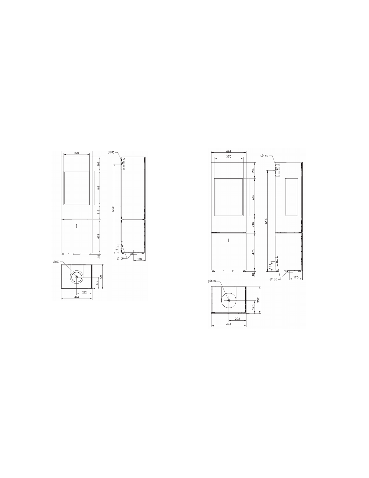
Dimensional drawing of SEO S
Dimensional drawing of SEO L
Page 9

GB
GB 9
2.3 INSTALLATION / ASSEMBLY
Your SEO S / SEO L stove must be installed on floors made of non-flammable
materials with a sufficient load-bearing capacity. Please observe the overall
weight (cf. Chapter 2.2 Technical data on page 7)! The load-bearing capacity may have to be ensured by a sufficiently thick board (weight distribution).
When selecting the installation site, also note the necessary measures for
fire protection in the floor area (cf. Chapter 2.5 Fire protection on page 12).
The stove is placed on the floor in compliance with the safety distances (cf.
Chapter 2.5 Fire protection on page 12) and aligned horizontally. The feet
are adjustable in height.
2.3.1 CHANGING THE FLUE GAS CONNECTION
DIRECTION
The stove is prepared for the flue gas connection at the top when delivered.
The flue gas connection position can be changed to the back. If the position
of the flue gas connection is changed, the following assembly steps must
be performed:
Installation from back to top
As a first step, remove the top sealing cover by pulling it forwards. Lift off
the blanking plate with the help of the recessed aperture. Dismantle the
inner cover plate by unfastening the two screws (Fig. 2a).
In the next step, remove the flue gas connector on the back of the stove by
unfastening the hexagon screws (waf 13 mm) (Fig. 2b).
Fit the unfastened connection journal at the top of the stove connection
flange (Fig. 2c) with the help of the two hex screws. Now fit the cover plate
removed in step 1 back to the inside rear wall panel using the two screws.
Seal the outer rear cladding panel with the help of a second cover plate
supplied in the stove combustion chamber.
Finally, slide the cladding cover removed in step 1 back onto the top plate
(Figs. 2d+2e).
Make sure that the sealing elements are correctly positioned under the
dummy cover and the flue gas outlet and ensure a tight seal.
Note for SEO S: If the SEO S model is connected to the rear flue point, this
blocks the turning function!
1. Remove the 3 cladding parts at the top in the following sequence (Fig.
2a):
- Cap (forwards)
- Blanking plate (upwards)
- Inside cover plate (upwards)
2. Remove the back connecting socket by unfastening the two screws (Fig.
2b)
3. Fit the connecting socket on the top appliance flange using 2 screws
(Fig. 2c).
4. Fit the 3 back cladding parts (Figs. 2d+2e)
Page 10
GB 10
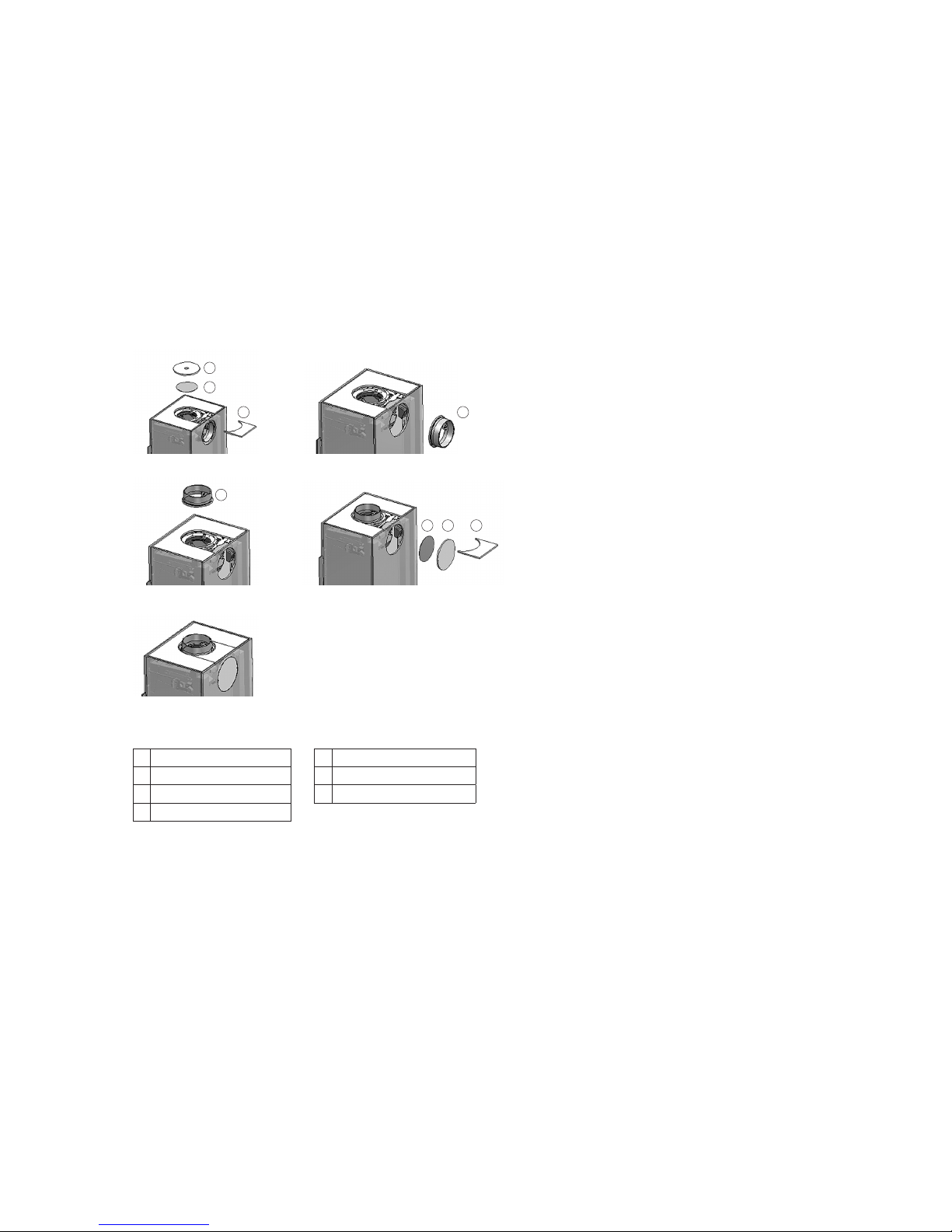
Fig. 2a Fig. 2b
Fig. 2c Fig. 2d
Fig. 2e
1
2
3 4
4
5 6 7
1 Blanking 5 Cover plate, inside
2 Cover plate, inside 6 Cover plate, outside
3 Cap 7 Cladding cover
4 Pipe nozzle
Installation from top to rear occurs in reverse order:
2.4 COMBUSTION AIR SUPPLY
The combustion air can be supplied in accordance with Chapter 2.4.1 Open
flue and Chapter 2.4.3 Closed flue in different ways.
2.4.1 OPEN FLUE OPERATING METHOD
Your ambiente SEO S / SEO L stove draws the combustion air from the
installation area (open flue operation). Ensure that there is a sufficient supply of fresh air to the installation area (for more details, refer to the applicable regional Fire Installation Ordinance (German ‘FeuVO’), DIN 18896,
applicable rules of technology etc.).
The fresh air supply must be checked by the installer and the operator.
When operating several fireplaces in a single room or linked space, ensure
that sufficient air is available for combustion! It is possible that there is not
a sufficient supply of fresh air if the windows and doors are sealed (e.g., in
combination with energy saving measures).
As a result, the ventilation of the stove can be affected. This can also
adversely affect your well-being and, potentially, your safety. If necessary,
an air valve must be installed near the pellet stove for the additional supply
of fresh air, or a combustion air line must be routed outwards (see 2.4.2) or
in a well-ventilated room (except for the heating room). In particular, ensure
that the necessary combustion air pipes are open during the operation of
the fireplace insert.
This means that simultaneous operation with a ventilation system (e.g.
extractor hood, bathroom fan, etc.) in the same room or connected space
can adversely affect the function of the stove (to the point of smoke or flue
gas accumulating in the living room, despite the firebox door being closed).
It is therefore prohibited to operate appliances of this kind simultaneously
with a fireplace without first taking appropriate precautionary measures.
Page 11

GB
GB 11
2.4.2 SEPARATE COMBUSTION AIR SUPPLY
The stove can be supplied with combustion air separately. The separate
combustion air connection is located on the underside of the appliance
(Ø = 100 mm). The combustion air line to be attached can be connected
underneath or at the back. A connection is integrated in the plinth for a
bottom connection.
To connect up combustion air, the following steps must be taken.
Assembly of the combustion air channel on the underside of the
appliance:
1. Place the appliance above the combustion air port in the floor and
remove the cladding plate (Fig. 3a).
2. Next, remove the sealing cover (Fig. 3b).
3. Connect the combustion air neck to a flexible and removable combustion
air line. If the combustion air connection is rigid at floor level, the separate combustion air nozzle supplied must be pushed into the connection
to form an airtight seal.
4. Finally, press together the combustion air line and install the combustion
air neck (Fig. 3c).
Fitting the combustion air channel to the back of the appliance:
1. First of all, unscrew the outer and inner cover plates (Fig. 3d).
2. Now fit the combustion air nozzle (Figs. 3e+f).
3. Lastly, connect the combustion air nozzle with the combustion air line.
When connecting a pipe connection to the combustion air neck, the combustion air can be supplied to the stove from the outside or from other
rooms such as the cellar. When connecting the stove to a combustion
air line, the TROL instructions (technical rules), DIN 18896, etc. must be
observed and applied.
1 Cladding plate
2 Cap
3 Combustion air neck
In particular, ensure that the dimensions of the pipes are adequate!
2
3
Fig. 3a Fig. 3b
Fig. 3c Fig. 3d
Fig. 3e
1
Fig. 3f
2
3
3
Page 12

GB 12
The combustion air openings and lines must not be closed or blocked unless
it has been ensured that the fireplace can only be operated with an open
lock by means of special safety equipment. The cross-section must not be
narrowed by a fastening or a grille. A shut-off valve must be installed, if
this combustion air feed pipe runs outside the building. In doing so, it must
be possible to easily determine the shut-off device setting from outside of
the connecting line. This arrangement allows the feed pipe to be insulated
to guard against the formation of condensation. The pipe should be positioned so that no water or other foreign substances from outside cannot get
into the stove, and that any condensation formed can run out of the pipe.
Even with a separate combustion air line for the stove, its operation can be
impaired by a ventilation system. Therefore, simultaneous operation is not
possible.
In accordance with regulations, combustion air lines crossing a fire wall in
buildings with more than two floors must be established in such a manner
that smoke or fire cannot be transmitted to other floors or fire compartments. Country-specific and local fire safety regulations must be observed!
2.4.3 CLOSED FLUE OPERATION
The SEO S / SEO L closed flue stoves have been developed for use with
residential ventilation systems for a vacuum range of up to 8 Pa in the
installation area and can be operated without additional safety equipment.
The combustion air must be supplied in airtight lines from the outside or
via an LAS system to the device for room-air-independent operation without
fail. To do this, the combustion air duct must be permanently sealed to the
combustion air neck (connection type back or bottom) of the stove.
When connecting the close flue stove to a combustion air line, the TROL
instructions (technical rules) and DIN 18896, etc. must be observed and
applied. In particular, ensure that the dimensions are adequate! Comply
with all country-specific and local fire safety regulations! Make sure that
the pipes are always airtight.
2.5 FIRE PROTECTION
The handover inspection of your stove before commissioning is performed
by the chimney sweep responsible. You can also advise the chimney sweep
prior to installation about installation conditions on site, and can provide
advice on how to install your stove properly.
General information on fire prevention
Stoves are heat generators and are subject to regulations and necessary
measures for fire protection. Right from selection of the installation site
stage, fire regulations and recommended minimum individual clearances for
the appliance must be observed.
Basically, a minimum wall clearance of 5 cm to the back wall must be
adhered to. For reasons of safety and fire protection, make sure that large
distances to walls to be protected or combustible components are maintained. See the following installation examples.
The following table documents the permissible safety distances. Using the
diagrams (Figs. 4a-4f), match the mounting situation, taking into account
the specified distances that need to be complied with.
During installation, please pay attention to the fire protection instructions
and contact your local chimney sweep with any questions you may have.
• Mounting walls that are non-combustible or which do not require protection are able to withstand permanent exposure to tempera-tures > 85°C
thanks to their structure and material type.
• Combustible mounting walls in need of protection (e.g. stud partition
construction) must be protected from temperatures above 85°C.
Page 13

GB
GB 13
Before installing the stove, it is necessary to evaluate the mounting walls. If
it is not possible to identify the precise type of installation wall, a specialist
(chimney sweep) needs to be brought in.
• Wallpaper as wall coverings in accordance with DIN 4102-1 are
non-combustible components and do not require special precautions
for fire protection. Ensure here that the underlying structure of the wallpaper (e.g. timber frame construction) is very easily ignited or must be
protected and appropriate precautions must be taken!
• Ensure that the minimum clearances from chimney connecting piece to
combustible components are adhered to (see Chapter 2.7 Connecting
flue pipes on page 15).
• Combustible objects must not be located at a distance of 50 cm above
the fireplace!
Floor coverings near the fireplace:
Floors made of combustible materials in front of the firebox opening must
be protected by a board made of non-combustible materials. The board
must extend over at least 50 cm to the front and at least 30 cm to the side
(measured from the combustion chamber opening or viewing window)!
No combustible components, furniture, curtains or decorations may be
placed in the area of direct radiant heat of the fire door or inspection glass.
This distance may be reduced to 400 mm if radiation protection plates are
installed between the fireplace and combustible structures on both sides.
Installation example for the SEO S:
1. When installing against a straight wall, maintain the following distances
between that wall and your SEO S stove: a minimum distance of 160
mm must be maintained behind any combustible components (Fig. 4a)
2. For installation in the corner of a room, maintain the following wall distances: If the stove is installed as shown as in Figure 4b, a minimum
distance from the SEO S of 160 mm must be maintained to the sides of
combustible components.
Fig. 4a
Fig. 4b
Page 14

GB 14
If the stove is installed as shown in figure 4c, a minimum distance of
160 mm at the back and of 600 mm at the side must be main-tained. If
the wall is in the radiant heat area, fit a thermal protector to this area.
3. For floor coverings in close range:
Floors made of combustible materials in front of the combustion chamber opening must be protected by a board made of non-combustible
materials. The board must extend at least 670 mm to the front and at
least 570 mm to the side! Due to the fact that the SEO S fireplace can
rotate, the floor covering needs to be protected across a larger area
(Fig. 4d).
Abb. 4c
Abb. 4d
Installation example for the SEO L:
1. For installation against a straight wall, the following wall spacings must
be maintained to your SEO L stove: a minimum distance of 160 mm must
be maintained behind combustible components (Fig. 4e).
2. Floors made of combustible materials in front of the firebox opening
must be protected by a board made of non-combustible materials. The
board must extend at least 500 mm to the front and side! (Fig. 4f).
Abb. 4e
Abb. 4f
Page 15

GB
GB 15
Stove
Distance to the
rear wall
Distance to side
wall
Distance in the area
of direct radiant
heat of the view
pane.
Dimensions of the
fire protection floor
covering
A (mm) B (mm) C (mm) D (mm)
combustible
No
protection
required
combustible
No
protection
required
combustible
No
protection
required
Length x
Width
Radius (with
round floor
covering)
SEO S 160 50 310 200 800 800 500 x 300 500
SEO L
160 50 560 250 800 800 500 x 300 500
2.6 SHUT-OFF DEVICES
Flue gas systems must be created as per the technical rules of the German
Association of Tiled Stove and Hot-Air Heating Systems.
Stoves must feature a shut-off valve on the exhaust path . These devices
must not be self-closing and must not be positioned such as to prevent or
hinder the inspection and cleaning of connecting pipework. The position of
the shut-off device must be visible from the outside, e.g., from the position of the operating handle. Shut-off devices may only be installed in the
exhaust manifold or collecting pipe, the flue gas pipe stub or the pipeline
connecting piece.
2.7 CONNECTING PIECES
Connecting pieces: your SEO S / SEO L stove is connected to the chimney
by ø 150 mm connecting pieces made from steel sheet at least 2 mm thick.
These must comply with DIN 1298 or DIN EN 1856-2 and they must be
connected to the chimney in accordance with DIN 18160 or the regulations
that apply in the country concerned.
Ensure that the flue gas pipe is installed in the shortest possible route
upwards towards the chimney. The number of bends in the flue gas pipe
should be kept to a minimum. In addition, the flue gas pipe must be
connected to the chimney with a bricked-in wall lining and sealed. If necessary, the flue pipe may need to be secured with brackets to assure sufficient
stability. If the flue gas pipe is routed through components with flammable
building materials, the flue gas pipe must be insulated as specified in the
regulations.
The connecting line must always be mounted in such a manner that it is
possible to clean the connecting line at any time. This must be ensured
through a sufficient number of cleaning openings.
Depending on the information provided by the flue gas pipe manufacturer,
the minimum distance from the chimney connecting piece to combustible
components may increase the distance between the stove and combustible
building components. The specified minimum distances to combustible
components as stated in these instructions refer to the fireplace and must
be adjusted if necessary (see Chapter 2.5 Fire protection).
Ensure that a cleaning opening is located above the flue pipe connection
with gas evacuation to the top.
2.8 INTEGRATED THROTTLE VALVE
A throttle valve is integrated in the exhaust flue above the deflector plate in
the SEO stove. When the fire door is closed, this throttle valve is in its starting position. The exhaust gases can escape upwards through an opening
cross section in the sheet metal panel, optimally adjusted for combustion.
Whenever this fire is opened, e.g. for adding fuel, the throttle valve swivels
upwards, greatly increasing the opening aperture for the exhaust gases.
This ensures that the exhaust gases do not escape into the room as a result
of the change in pressure in chimney and combustion chamber while the
fire door is open.
Page 16

GB 16
The initial position of this flap is set ex-factory for optimum air cross-sections. Depending on chimney conditions, this can cause impaired or insufficient combustion, and/or to smoke escaping into the room. In such cases,
it is possible to adjust the position of the throttle valve and therefore also of
the exhaust cross sections.
1. To do this, remove the top cladding parts from the top plate. (Fig. 5a).
2. Now you have access from above to the rod mechanism on the right side
of the stove that controls the throttle valve. The driving rod, mounted
with the help of a lock nut, can be used to adjust the position of the flap
(Figs. 5b and 5c).
3. To enlarge the opening cross section in the exhaust gas flue, unfasten
the lock nut and turn the driving rod further towards the back.
4. Then tighten down the lock nut again firmly.
5. Finally, place the cladding parts back onto the top plate.
Fig. 5a
Fig. 5b - Bottom view
Fig. 5c
1 2
1 Driving rod.
2 Lock nut
2.9 CLOSING FORCE FOR THE FIRE DOOR
The closing force of the self-closing Type A1 fire door is factory-set to its
optimum level. To change the closing force, the setting can be adjusted
using a spring.
1. To do this, remove the top cladding parts from the top plate. (Fig. 6a).
2. You now have access to the spring mechanism. (Fig. 6b).
3. Unfasten the two hex screws with flange and slide the holder in the two
elongated holes. You increase the closing force of the door by continuing to tighten the spring (“tighten clockwise”), and you decrease the
closing force of the door by relieving tension on the spring (by turning it
anti-clockwise) (Fig. 6c).
Page 17

GB
GB 17
Fig. 6a
Fig. 6b
1
2
3
1 Reduce force
2 Increase force
3 Hex screws with flange
Fig. 6b
3. OPERATING MANUAL
Read these installation and operating instructions carefully before installing
and starting up your stove. All objects must be removed from the combustion chamber (except for combustion chamber liner).
Ask your specialist dealer to explain to you how to operate the SEO S / SEO
L stove and how it functions.
National and European standards and local regulations for operating the
fireplace must be observed!
3.1 GENERAL INFORMATION ON OPERATION
• Small children, elderly or infirm persons: As is the case with all heating
devices, it is expedient that you attach a protective fixture for these
groups of persons, as the view pane and the lining parts of the stove can
become extremely hot! Danger of burn injuries!
• Never leave these groups of persons unattended near the stove when
a fire is burning or has just been extinguished! Make these individuals
aware of these risks.
• No combustible objects may be placed or laid on the free surfaces and
the panels of the SEO S / SEO L stove. Do not place items of clothing on
the stove to dry. Racks for drying clothing may only be placed outside
the radiation area!
• Burning fuel releases thermal energy which heats up the various parts
of the stove, such as the surfaces, the door, the door handle and control handle, the viewing pane, the flue ducts, etc. Do not attempt to
touch these components without adequate protection (i.e. heat-resistant
gloves).
Page 18

GB 18
• The SEO S / SEO L stove may only be operated with the fire door closed.
The door should always be kept closed, even when cold. The door is only
opened for lighting up and for refuelling.
• The fireplace must never be modified! Do not insert any foreign component (any component not expressly approved by Arcadia) into the
combustion chamber, combustion passages or exhaust gas flue. Any
such modification of the fireplace without express approval will void the
warranty and operating permit.
• This applies in particular when operating several fireplaces in a single
room or linked space. It must be ensured that sufficient air is available
for complete combustion!
• Your appliance is designed to operate as a temporary or short-term combustion device. Continuous burning cannot be achieved even through
withdrawal of the combustion air and is not permitted! A longer heating
period is achieved by repeatedly by adding suitable amounts of fuel to
the fire.
3.2 S-THERMATIK NEO
Your SEO stove is equipped with S-Thermatik NEO burn-up equipment.
Supply voltage 230V AC
Power consumption during operation: approx. 10VA
Power consumption in "Stand-by" mode: approx. 6VA
Safety class I
Degree of protection IP 20
For further information about the burn-up control, please request the assembly and service instructions from the manufacturer of the S-Thermatik NEO.
3.3 FUNCTION OF THE ROTARY-BASE FOR SEO S
Attention: The swivel function is not available when the exhaust flue gas
connection is at the back!
The SEO-S model is divided into two areas: the upper combustion area and
the lower maintenance and storage area. The upper section of the stove can
be turned by 30° in either direction using the rotary base at this interface
(Fig. 7a).
Fig. 7a
2
1
1 Oberer Feuerungsbereich – lässt sich um 30° in jede Richtung drehen
2 Lower maintenance and storage area
3 Remove stop.
Page 19

GB
GB 19
To activate the swivel function, you must first operate the stop on the rotary
base. This detent pin is located centrally in the lower storage area (Figs.
7b and 7c).
After pulling out the spring-actuated stop,
the top cube can be swivelled 30° in either
direction. After swivelling, lock the stove in
its final position by engaging the stop (Fig.
7d).
Fig. 7c
Fig. 7b
3
Fig. 7d
3.4 RATING PL ATE
The rating plate is located on your warranty certificate and also on the
back of your stove. It contains technical data and notes. Never remove the
rating plate because it confirms that the appliance has been tested, and it
is also required for the acceptance procedure and annual inspections by the
chimney sweep.
4. COMBUSTION
4.1 INITIAL COMMISSIONING
The SEO S / SEO L stove must only be installed and set up by a specialised company. Initial commissioning must only be executed by an expert
employee of the installation company. A certificate confirming proper
installation and proper adjustment / function of all control components and
safety components must be given to the owner / operator of the system (see
sample, chapter 10).
When first putting your appliance into service, only start a moderate fire.
This enables you to avoid cracks in the firebox covering (which may still
contain residual humidity before the first firing). Slowly increase the heating
power to about 30% above nominal heat output by setting the fire 3 to 5
times to give the corrosion coating applied to the surfaces time to ‘burn
in’ properly. During this process, the paint can become slightly soft, do not
place any objects on the stove and do not touch the appliance. During this
burning-in process, an unpleasant yet harmless odour (sometimes accompanied by the build-up of smoke) may be given off. It is therefore important
to ensure that the room is well ventilated during the burning-in process.
Open all doors and windows to the outside of the building.
Page 20

GB 20
During heating and cooling, metallic grinding noises may be heard as the
components of your stove expand or contract. These are completely normal
and arise as a result of material expansion caused by the high temperatures.
Note: It can be helpful for the lighting up to weigh the recommended
quantity of wood (1 - 1.5 kg) to estimate what (visual) quantity of wood
corresponds to this weight. This enables you to ensure that the stove is not
overheated as a result of you adding too much wood.
4.2 SEO OPERATING CONCEPT
4.2.1 THE ‘SEO APP’
Your SEO stove is controlled fully automatically by the integrated S-Thermatik NEO burn-up controller. To operate this appliance, the “SEO APP”
provides you with an information platform. With this, you can choose various
settings, e.g. the desired power/performance level, as well as request further information about the prevailing operating condition, historical data or
information about suspected faults.
This app is available for devices running Android and the IOS operating
system. It is called “SEO App” and it can be downloaded from the Play Store
or from iTunes.
To install the app, you must activated Bluetooth on your device, and you may
need to permit “Installation from unknown sources”.
The data link only functions using Bluetooth. The module is integrated in
the control system. Only ever one mobile device can be connected to the
controller at any one time. Another device can log in once Bluetooth is
switched off on the connected device, or until that device moves outside
reception range.
Note: Depending on the configuration of the tablet or smartphone being
used, a Bluetooth coupling code can be requested during first-time installation. To enable the connection between the stove and the tablet or smartphone, please enter this numerical string:
0 0 0 0
in the input screen.
4.2.2 THE INDICATOR
An illuminated indicator acts as a direct information communicator between
the SEO stove and the operator. It is recessed into the lower door of the
storage compartment. This provides basic information about the prevailing
operating status. For further information, please consult the “SEO App”
This indicator provides basic information about the prevailing operating
status and of any faults/operating errors with a range of light signals: Off,
continuously lit, pulsating flashes and rapid flashes.
Interaction levels
Simple feedback during operation
More complex settings
Monitor
Page 21

GB
GB 21
Here are the interactions in detail:
Indicator
LED - Off
Function
Appliance
OFF
Appliance is
in standby
mode
LED - On
Function
Appliance
ON
Appliance
is in normal
operation
LED -
pulsating flashes
Function
Add fuel
signal
Burn-up
ended - add
more fuel
LED -
flashes rapidly
Function
Fault
message -
door open
Overheating
Sensor
defect
4.2.3 START AND MENU STRUCTURE OF THE APP
After starting the app, the user can retrieve further items of information.
To do this, it is possible to navigate within the following menu structure.
For details of the individual levels and menu items, please consult the following sections:
Monitor
Fire area
Combustion
chamber
temperature
Room
temperature
Enjoy
Mode Settings
Languages
Sound on/off
Assistance Fire Monitor
Lighting Standard
burn-up
Adding
fuel
Eco Performance Statistics
Page 22

GB 22
4.2.4 STARTING LEVEL
The first level offers a choice between the following modes:
Fire area / Mode / Settings
Fire area
Mode
Settings
Fire area
Mode
Settings
4.2.5 FIRE AREA
All stoves detected in the scan range are displayed at the “Fireplace” menu
item. After selecting an appliance, a connection is established between the
app and the chosen stove.
Touch here to search for available appliances Search for available appliances
Touch here to search for available appliances
Touch here to search for available appliances
Touch here to create a connection
Touch here to create a connection
S-Thermatik Neo
Page 23

GB
GB 23
4.2.6 MODE
The following levels are arranged behind the Mode menu.
Assistance / Fire / Monitor
Assistance
Fire
Mode
Assistance
Fire
Mode
4.2.7 SETTINGS
Under the Settings menu item,
• the menu language can be selected (9 standard languages available)
• German • English • French • Italian • Spanish
• Dutch • Polish • Czech • Russian
• and the acoustic signal for adding fuel can be activated/deactivated.
Language
Sound on
Sound on
Sound off
Page 24

GB 24
4.2.8 ASSISTANCE
The assistance (Help) level provides the user with additional information
about the message on the illuminated indicator.
The indicator is lit continuously. The appliance is operating in normal mode.
Depending on operating condition, the symbols for “Lighting up” or “Full
burn-up” are displayed.
The indicator flashes with a pulsating light. The user is called upon to add
wood. This signal can also be amplified acoustically.
The indicator flashes in a fast rhythm. At the same time, a fault message is
displayed. The type of fault is described and is displayed on the welcome
screen (homepage).
LED - Off
LED -
pulsating flashes
LED -
flashes rapidly
Lighting Normal burn-up
Adding fuel
Warning
The following types of fault can be displayed:
• Open door! After filling, close door correctly.
• Overheating! Next time, add less fuel.
• Sensor defective! Contact your specialist dealer.
• Motor malfunction! Contact your specialist dealer.
4.2.9 FIRE
At the “Fire” level, the user has the option of choosing between 3 performance/power levels. The power levels
Eco (lowest power)
Enjoy (moderate performance)
Performance (maximum performance)
are illustrated by different sizes of flame symbol and these can be adapted
during the burn-up phase.
Eco Enjoy Performance
Page 25

GB
GB 25
4.2.10 MONITOR
At the Monitor menu, the prevailing combustion chamber temperature and
the room temperature can be queried online.
Also, using the Statistics button, a time plot (over a period of 3 hrs.) can
be displayed showing combustion chamber temperature, room temperature
and air intake (%).
Room temperature Combustion chamber
temperature
Statistics
Temperature
356°C
256°C
200°C
Air supply
100%
50%
0%
4.2.11 EXAMPLE OF MENU GUIDANCE
The following example shows how to set the desired power level:
Activate your tablet. This app appears on the user interface
Activate the app. The main
interface appears.
Select the Mode menu.
In the sub-menu, select Fire.
Fire area
Mode
Settings
Assistance
Fire
Monitor
Page 26

GB 26
The last 3 power stages saved are then displayed.
Select the desired power level (in this example, the middle stage
of Enjoy).
The selected power level is shown in red.
By clicking the arrow in the top
left corner of the screen (back),
you can return to the main
menu.
Eco
Enjoy
Performance
Eco
Enjoy
Performance
Fire area
Mode
Settings
4.3 HEATING-UP / FIRING
Lighting this stove is very easy if you follow the instructions below.
1. The SEO S / SEO L stove must only be fuelled with correctly inserted
combustion chamber line
2. The split timber is layered crosswise in the
centre of the combustion chamber, tapering
upwards (soft wood).
3. 3. Never place more than 1 kg - 1.5 kg per
burn-up in the fireplace
4. Place commercial firelighter cubes under the
stack of firewood to assist with lighting the fire.
(Paper is not recommended because it burns too
quickly and causes ash flight).
5. Never use methylated spirits, petrol, oil or any other
highly flammable liquids.
6. Light the fire at the firelighter cubes and leave the
fire door open about 3 - 5 cm. The fire should now
ignite brightly and burn intensely.
7. If the initial stack of wood burns well, add
smaller hardwood split logs logs or larger
softwood split logs logs in a haphazard stack.
8. You can learn more about the correct amount
of timber to add in the chapter on wood feed
quantities per hour (see Point 4.3.2).
9. Once the wood has burned down completely,
or once only hot embers are left, you can add
more firewood as required (the ideal fuel is
now hardwood).
Page 27

GB
GB 27
10. Do not open the door forcefully or gases may enter your living room
through a suddenly produced negative pressure. At first, open the door
slowly and slightly.
11. By putting fresh firewood onto hot embers
you prevent the possible release of smoke
when the door is opened.
12. Never repeatedly put more than the recommended amount onto the fire.
4.3.1 REFUELLING
Do not refuel until the indicator flashes in a pulsating manner and/or until
the acoustic signal sounds (if activated) (cf. chapter 4.2 SEO operating
concept).
Caution: Never add more than the recommended amount of wood (1-1.5
kg)! Otherwise there is a risk of overheating the stove.
1. Open the combustion chamber door very slowly (use the heat protective
glove), so that no turbulence can might cause smoke to escape into the
room.
2. Place the wood logs on the embers (bark facing upwards, cut ends to
either side). Make sure that the air supply is open! Embers must not be
smothered).
3. Close the combustion chamber door (use the heat-resistant glove!)
4.3.2 HOURLY WOOD CONSUMPTION RATE
In order to avoid damage due to over-heating (discolouration of the steel,
deformation, etc.) and to guarantee optimum performance over the lifetime
of the appliance, ensure that the stove is fuelled in the proper manner.
To prevent any risk of overheating, make sure that the maximum heating
capacity is never exceeded.
The recommended amount of wood feed per hour is 1-1.5 kg. The individual
wood logs should be no more than approx. 25 cm in circumference!
Please note: Larger feed quantities lead to overheating and damage to
the chimney insert. Wood pellets (briquettes) have a much higher heating
capacity than hardwood. The hourly feed rates are therefore to be keep 20%
less than with wood logs.
In the event of damage caused by overheating (an excessively high hourly
fee rate), we shall decline all warranty claims.
4.4 CONTROLLING HEAT OUTPUT
Heat output is controlled by regulating the amount of fuel being added, and
this should never exceed the recommended quantity of wood. Ensure that
the combustion chamber door is always firmly closed to prevent combustion
being accelerated by the uncontrolled inflow of air.
The performance of your stove is also dependent on the draught in your
chimney. This draught can be adversely affected by the cross-section of the
chimney, or by environmental factors such as strong winds etc.
4.5 ROOM HEATING OPTIONS / INDOOR CLIMATE
The room heating capability used to be quoted in accordance with the DIN
18893 standard (most recent edition being August 1987) so is no longer
a meaningful indicator for modern houses constructed after 1990. As a
comparison value, or for use in relation to older housing stock that fails to
comply with the thermal insulation standard of 1977, the old indication of
room heating capability may still be of interest.
Page 28

GB 28
Precise descriptions of the terms ‘favourable’, ‘less favourable’ and ‘unfavourable’ can be found in DIN 18893. The simplified description ‘favourable’
applies to the case, where the room under consideration only has one external wall and the remaining walls are adjacent to heated internal areas of the
building, ‘unfavourably’ on the other hand is based on two exterior walls and
adjacent unheated rooms.
The values given above refer to building fabrics that do not yet meet the
requirements of the Heat Insulation Ordinance of 1977 and that therefore
also constitute a simplification valid for room sizes of up to 200 m³. DIN
18893 standard recommended a calculation according to DIN 4701 for
rooms larger than 200 m³. Nowadays, room heating capacity estimates are
made in accordance with TROL guidelines and more detailed calculations in
accordance with DIN 12831.
4.6 HEATING IN THE SHOULDER SEASONS/DURING
UNFAVOURABLE WEATHER CONDITIONS
In the ‘shoulder seasons’ (transitional periods), that is, when outdoor temperatures are above about 15°C or under unfavourable conditions (catabatic/adiabatic winds, etc.) can lead to disturbances in the chimney draught
during a sudden temperature rise, so that the hot gases are not completely
removed. To combat this, less fuel should be used and the air supply setting
(see 4.2) should be increased. This burns the fuel more quickly (with larger
flames). and stabilises the draught. In order to prevent the build-up of ash,
the fire should be carefully stoked more frequently.
4.7 CHIMNEY FIRE
When burning wood (especially softwood), sparks can often be transferred
from the fireplace to the chimney. This can ignite the coating of soot inside
the chimney (if cleaned on a regular basis by a chimney sweep, this problem is unlikely to occur). The chimney catches fire. This can be recognized
by flames that blaze from the chimney opening, excessively flying sparks,
smoke and odours, as well as the chimney walls becoming progressively
hotter. It is important to act properly in such cases. You can alert the fire
brigade by dialling 999 (or 112 in Germany). The chimney sweep must also
be informed. Combustible objects should be located away from the chimney.
Attention: Do not attempt to extinguish the fire with water before the fire
brigade arrives on the scene. Temperatures in a chimney fire can reach up
to 1300°C. Extinguishing water would immediately turn to steam. A 10-litre
bucket of water yields 17 cubic meters of steam. The enormous pressure
created as a result could cause the chimney to disintegrate. After the chimney has burned out, this is to be examined by an expert for cracks or leaks
and to be repaired if necessary.
5. FUEL
The German ‘Wald in Not’ (Forest in Peril) Foundation formulates this aptly
in an informative brochure as follows: “Wood does not run up debts for
Nature. Wood is stored solar energy. Sunlight, water and carbon dioxide are
the building blocks that make wood. During the lifetime of the tree, sunlight
is chemically captured. Solar energy is stored in lignin and cellulose. When
burned, this is released again”.
For more information, please visit the website www.wald-in-not.de. Only
those fuels listed in the 1st BlmSchV (German Federal Emissions Protection
Ordnance) may be burned in stoves.
Page 29

GB
GB 29
The only fuels author-ized for fireplaces are firewood (recommended residual humidity of 20% or less) or wooden briquettes, as defined in DIN 51731.
Incidentally: A measuring instrument for determining the moisture of wood
logs does not cost much and can pay for itself quickly.
Do not use any other fuels
It follows from this that it is not permitted to burn:
• painted or plastic-coated wood
• Fibreboard or wood that has been treated with timber preservative
• Wood from Europool pallets
• Rubbish, household waste, old clothes
• Paper, paper briquettes, cardboard
• Damp wood (residual humidity > 20%)
• Plastic or foam of any kind
• Any solid or liquid materials that contain no wood
It is prohibited to burn these or other inappropriate materials in your stove.
When burning other materials than the permitted fuels, wood logs or wood
briquettes defined in DIN 51713, toxic gases can be formed that have
an adverse effect on the combustion process, and that may even cause
explosions.
Operating SEO S / SEO L stoves with other than the approved fuels renders
the warranty invalid!
Use small bits of wood for beginning to heat. Only use split wood as firewood
that is not thicker than about 8 cm at its thickest point. The optimum length
of firewood is approximately 25 cm. Please do not add too much wood at
one time. Instead, it is better to add smaller quantities of wood at regular
intervals. When adding fuel, the embers must not be completely covered.
5.1 CO2 NEUTRALITY
Wood only emits as much carbon dioxide as it had previously gained from
the air and incorporated when it was a living tree. It is immaterial whether
the wood burns or rots in the forest – the carbon dioxide output always
remains constant. New trees absorb the carbon dioxide that the wood emits
when burned, and a closed natural carbon cycle is the result.
Conclusion: When wood burning, nature remains in balance. German Law
legislates for the sustainable management of forests. This obligation leads
to an increase in timber volumes, since the average increase in timber is
40% greater than the amount of firewood and timber that is consumed.
5.1.1 WO O D STO R AG E
In general, it is recommended to store firewood for approx. 2-3 years, the
wood should be protected from dampness and well ventilated (e.g. under a
roof overhang on a side of the building protected from the weather). When
properly stored, a wood moisture level < 20% is achieved much more
quickly. Therefore, the firewood should be split when stored, because the
bark prevents the moisture from escaping. To ensure good ventilation, you
should leave a hand gap distance between the logs, so that air can circulate
freely and so escaping moisture can be well absorbed by the air. A gap of
about 20 - 30 cm to the ground should be maintained below the log pile.
The re-absorption of moisture due to precipitation (e.g. rain or snow) should
be avoided. The storing of wood in garages, under plastic sheets or in poorly
ventilated basements is not recommended as this makes it difficult for any
moisture in the wood to escape. Use a readily available wood humidity
measuring appliance to check your fuel.
Page 30

GB 30
5.2 YOUR CONTRIBUTION TO ENVIRONMENTAL
PROTECTION
Whether or not your SEO S / SEO L stove burns in an environmentally-friendly
way very much depends on the choice of fuel and the manner in which the
fire is operated. The following tips should help you operate your stove with
minimum harm to the environment.
• Use as little wood containing resin as possible (fir, pine, spruce). These
types of wood cause soot to form on the window of your stove more
rapidly, and also cause more sparks. Therefore, for safety reasons, only
use deciduous woods (birch, beech, oak, fruit tree timber).
• Adapt the amounts of wood you add to the fire to suit your heating
requirements.
• It is advisable to purchase a wood humidity measuring appliance (inex-
pensive and easy to operate).
You can check that combustion in your stove is clean and relatively free of
pollutants in the following way:
• The ash should be white. If the ash is dark, this indicates the presence of
residual carbon, which in turn indicates incomplete combustion.
• The flue gases in the chimney after the lighting up phase should be almost
invisible (the less visible the flue gases, the better the combustion).
• The firebox lining in your stove should be bright after combustion, not
sooty.
Note: The fireplace must not be used as a waste incinerator! Furthermore,
remember that the device is designed for temporary burning only. Continuous burning cannot be achieved even through withdrawal of the combustion
air and is not permitted!
6. CLEANING AND CARE
The stove may only be cleaned when cold. Bear in mind that when cleaning
the room in which the fireplace is installed and any clothing may become
dirty. We recommend that you protect the area around the combustion
chamber opening with foil or a cloth against dirt and to wear work clothes.
After cleaning, all removed parts should be refitted.
6.1 CLEANING THE FIREBOX/CLADDING PARTS
• The stove, the combustion chamber, the smoke collecting chamber with
the heating gas diverter, the combustion air supply and the connecting
pieces to the chimney must inspected at regular intervals for deposits and cleaned if necessary annually, possibly also during and after
each heating season and after cleaning the chimney (consult your stove
dealer or responsible chimney sweep). Use a hand brush and/or an ash
vacuum (specialist dealer) to remove the debris. The chimney should be
cleaned at regular intervals by the chimney sweep! Furthermore, the
stove should be checked annually by a specialist.
• Flue gas deflector: A flue gas deflector is also located above the combustion chamber and in the exhaust manifold. This component must be
cleaned at regular intervals. The flue gas deflector can be removed for
this purpose. This must be raised, then tilted and removed through the
firebox. The deposits on the deflector can be cleaned off simply with a
handheld brush.
• Ash removal: your SEO S / SEO L stove is suitable for burning dry wood
that burns best in its own ashes. However, if you want to remove the ash
from the combustion chamber, open the fireplace door. Brush out the
ash, e.g. onto a dustpan or shovel, or use an ash vacuum to remove ash
from the combustion chamber.
• Please note that the embers can remain hot up to 24 hours or more!
Page 31

GB
GB 31
• Cleaning of ceramic glass pane: The glass view pane can be easily
cleaned using a commercial fireplace cleaner, that you can purchase at
your specialist dealer. Then, wipe (do not rub on the glass!) with a dry
cloth. The fibreglass seals should not be soaked with detergent!
• Painted surfaces and the cladding parts can be cleaned with a moist
cloth (do not use a microfibre cloth!).
• Glass surfaces can be cleaned with a standard glass cleaner and a soft
cloth (do not use a microfibre cloth!).
• Stainless steel surfaces can be cleaned with standard stainless steel
cleaning agents! Only use in the direction of the finish!
• Natural stone surfaces can be cleaned with a wet cloth or with appropriate standard cleaning agents!
• Ceramic surfaces can be cleaned with a damp cloth or with appropriate
commercial cleaners!
During the hot season, remove any dust on and below the stove furniture
regularly as dust particles can burn or char. This can cause dirt in the room
and on the furnishings where the fire is installed.
6.2 FIREBOX LINING
In the heating-up phase it is normal for the lining to have a dark coating.
Once the operating temperature is reached, the combustion chamber lining
will be burned off. Cracks are not grounds for a justified complaint. The
lining is exposed to very high loads. A tension or expansion crack is not a
matter for concern and is not a functional deficiency. However, any broken
and shifted combustion chamber fireclay must be replaced.
If replacement chamotte is required, you can order this from your stove fitter
stating the relevant order number.
6.2.1 FIREBOX LINING SEO S
Item Designation Item no. Quantity
Single stone, fireclay
1 Flagstone, front 1054254 1
2 Flagstone, back 1024256 1
3 Back wall stone, right/left 1054257 2
4 Back wall stone, bottom 1054258 1
5 Back wall stone, top 1054259 1
6 Sidewall stone, right 1054821 1
7 Sidewall stone, left 1054822 1
8 Deflector plate 1053975 1
Complete set, fire clay
Fireclay set, complete, without baffle plate 1054824 -
Accessory
Grills (small) 180/110 mm 1019059 1
Page 32

GB 32
6.2.2 FIREBOX LINING SEO L
Item Designation Item no. Quantity
Single stone, fireclay
1 Flagstone, front 1054254 1
2 Flagstone, back 1024256 1
3 Back wall stone, right/left 1055603 2
4 Back wall stone, bottom 1055605 1
5 Back wall stone, top 1055604 1
6 Edge stone, right 1054260 1
7 Edge stone, left 1054261 1
8 Deflector plate 1053975 1
Complete set, fire clay
Fireclay set, complete, without baffle plate 1054778 -
Accessory
Grills (small) 180/110 mm 1019059 1
6.3 MAINTENANCE
The door seal must be checked at regular intervals! This seal must be
replaced if necessary (in case of wear, breakage, etc.). The firebox lining is made of natural products and must therefore be checked at regular
intervals.
As long as the firebox lining maintains its position in the firebox and does
not break, it is fully functional. A crack in the chamotte is therefore no cause
for a complaint. To ensure proper functioning, it is essential that an annual
(if possible before the heating season) maintenance of the stove be carried
out by a specialist!
Furthermore, the following applies to closed flue stoves: Proper door seal is
an essential item for room-air-independent operation of the stove. Perform
a visual inspection of the seal (pressure, wear, bulges) at least once per
heating season and replace it immediately if damaged.
The fireplace must never be modified! Only original spare parts that have
been approved by the manufacturer may be used! If you have any questions,
please contact your specialist dealer.
6.3.1 LUBRICATION MANUAL FOR DOOR LATCHES
WITH SMART-CLOSE
Stoves with Smart-Close door locking mechanisms must be lubricated at
regular intervals to assure problem-free operation (once per heating season). For this purpose, the scope of delivery of each fire area includes a tube
of special stove lubrication compound.
This lubrication compound is applied to facilitate ease of movement of heavy
combustion chamber doors, and to prevent noise caused when opening
and closing the doors. The lubricating compound must be applied at least
once a year to the Smart-Close door locking mechanism and its associated
Page 33

GB
GB 33
roller. In the case of fireplaces which are
used frequently or very frequently, it may be
necessary to shorten this lubrication interval.
With the SEO S / SEO L stoves, the door lock
springs may be located below and/or above,
as well as to the side of, the fire door. In order
to lubricate the lock, you may use a standard
cotton swab/Q-tip as an aid.
Open and secure the fire door. Apply a little lubricant compound to the
cotton swab and use it to coat the spring support on the door lock; Turn the
locating roller on the body of the stove during this application process. Open
and close the combustion chamber door a few times and, if necessary, apply
the copper paste once again
Attention! Ensure that no copper paste comes into contact with trim components or similar. Remove dirt and grime directly with a cotton cloth. Never
operate the equipment during intervening periods
7. TROUBLESHOOTING
You can remedy the following problems on your SEO S / SEO L product
yourself, but for other problems, please contact your specialist dealer or
your tiled stove installer.
7.1 GLASS BECOMES SOOTED HEAVILY, RAPIDLY AND
UNEVENLY
If this did not occur from the very start, please check the following points:
• Have the correct burning materials and equipment been used?
• Combustion air control fully open (actuating lever turned fully to the
left)?
• External combustion air line free?
• This means that soot accumulates quickly, within just half an hour. (it
is normal for the fireplace unit to become progressively dirtier from
operation of the system. a car windscreen gradually gets dirty during a
drive). To remedy this, ensure that no split logs are in direct contact with
the window, or are lying very close to it.
• Is the seating of the seal perfect?
• Is the wood dry enough?
• Has enough wood been added? (insufficient amounts of wood can result
in temperatures in the stove not being high enough).
7.2 FIRE IS DIFFICULT TO IGNITE
If this did not occur from the very start, please check the following points:
• Have the correct burning materials and equipment been used?
• Is the wood dry enough?
• Is the wood thin enough?
• Is a sufficient air supply assured.
Page 34

GB 34
• Not a shoulder season?
• No thermal inversion?
• Is the combustion air controller fully opened?
• External combustion air line free?
7.3 SMOKE ESCAPES WHEN ADDING WOOD
If this did not occur from the very start, please check the following points:
• See all questions under Point 7.1
• Is the complete burn-up phase reached?
• Is the bypass flap open?
• Has the required level of negative pressure been reached?
• Is the chimney unobstructed?
• Has your stove already reached operating temperature?
• Did you open the door slowly at the beginning?
7.4 EXCESSIVELY RAPID BURN-UP /
RATE OF WOOD CONSUMPTION IS TOO HIGH
If this did not occur from the very start, please check the following points:
• Is the wood split in large enough log sections?
• Is the chimney draught too strong?
• Have you reduced the combustion air control (by turning the actuating
lever slightly to the left)?
• Are you using hardwood with 15-18% residual humidity?
• Is the door completely closed?
• Have you complied with the recommended amount of wood?
8. GENERAL WARRANTY CONDITIONS
8.1 APPLICATION AREA
These standard warranty terms apply for the contractual relationship
between the manufacturer, Spartherm Feuerungstechnik GmbH, and the
dealer/distributor. They are not congruent with the contractual and warranty
terms which the dealer/distributor offers his customers in individual cases.
8.2 GENERAL INFORMATION
This product has been manufactured in compliance with current standards
of quality control. The materials used have been carefully selected and - like
the production process - are subject to on-going quality control. Specialist
knowledge is required when assembling and installing the product. The
product must, therefore, only be installed and started up by specialist technical staff, in compliance with current statutory provisions.
8.3 WARRANTY PERIOD
The standard warranty terms only apply within Germany and the European
Union. The warranty period and scope of the warranty are ensured within the
framework of these conditions outside the statutory warranty which remains
unaffected.
The company Spartherm Feuerungstechnik GmbH offers a 5-year warranty
for:
• Main carcass combustion cells
• Main carcass fireplace stoves
• Main carcass fireplace cassettes
• Main carcass fireplace doors
Page 35

GB
GB 35
Spartherm Feuerungstechnik GmbH offers a 24-month warranty in respect
of the sliding door mechanism, operating components such as handles, setting levers, shock absorbers, electrical and electronic components such as
fans, rotational speed controllers, the manufacturer’s original spare parts,
all items purchased as additional extras and all safety appliances.
Spartherm Feuerungstechnik GmbH offers a 6-month warranty in respect of
consumables mounted in the combustion / firebox area, such as fire clay,
vermiculite, fire grates, seals and glass ceramic.
8.4 REQUIREMENTS FOR THIS WARRANTY TO BE
EFFECTIVE
The warranty period shall begin on the date, on which the product is delivered to the dealer / distributor. Invoices or delivery notes may be used as
confirmation of the warranty commencement date. The warranty certificate
for the product must be presented by the claimant upon making a warranty
claim. Spartherm Feuerungstechnik GmbH is not obliged to satisfy any claim
if such documentation is not presented.
8.5 EXCLUSION OF WARRANTY
This warranty does not cover:
Product wear:
• Chamotte/vermiculite: This is a natural product that expands and con-
tracts with every heating process. This can cause cracks to appear. As
long as the lining elements stay in position in the combustion chamber
and do not break, they are fully functional.
• The surfaces: Discolouration in the paint finish or on the galvanic sur-
faces that is due to thermal stress or overload.
• The elevating door mechanism: failure to comply with installation guidelines, resulting in overheating of the deflection rollers and bearings.
• The seals: Decrease in the leak tightness due to thermal load and
hardening.
• The glass panes: contamination, due to soot or other burnt-on combustion materials and visual deterioration due to thermal loading.
• Careless transportation and/or incorrect storage:
• Inappropriate or careless handling of fragile components
• Such as glass or ceramics.
• Improper handling and/or use
• Lack of maintenance
• Incorrect installation or appliance connection
• Failure to comply with installation instructions and operating instructions
• Technical modifications to the appliance by persons that are not
employed by the manufacturer
8.6 RECTIFICATION OF DEFECTS / REPAIR
Independent of any statutory provisions acknowledged as taking precedence
over the terms of this warranty, all necessary repair works resulting from
material or manufacturing defect shall be carried out free-of-charge and
shall not invalidate the remaining provisions of the warranty.
Within the scope of this warranty promise Spartherm Feuerungstechnik
GmbH reserves the right to either remedy the fault or replace the device free
of charge. The elimination of defects shall take precedence. The terms of
this warranty shall not extend to any damage or compensation not covered
by statutory provisions.
Page 36

GB 36
8.7 EXTENSION OF THE WARRANTY PERIOD
The warranty period shall automatically be extended, where claims made in
respect of these warranty provisions result in the repair or replacement of
defective equipment.
8.8 REPLACEMENT PARTS
Only the manufacturer’s own components, or replacement parts recommended and approved by the manufacturer, shall be used for appliance
servicing and repair.
8.9 LIABILITY
Damages and claims for compensation which are not the result of delivery of a defective appliance from Spartherm Feuerungstechnik GmbH are
excluded and are not part of this warranty promise.
The above shall not include claims made in respect of statutory legal
requirements.
8.10 FINAL COMMENTS
In addition to these warranty conditions and our commitment to them, our
dealers and contractual partners are pledged to assist you in both word and
deed. We expressly recommend that our fireplaces and stoves are regularly
inspected by a qualified technician.
Subject to technical changes and errors.
Page 37

GB
GB 37
9. SEO S / L COMMISSIONING PROTOCOL
Date Device no.:
(see rating plate)
Installation company:
Has the actual delivery pressure been checked?
yes no
Negative pressures greater than 20-25 Pa can influence correct
operation. The pane can become increasingly contaminated or noise
can be intensified!
The fireplace operator has been instructed regarding operation and
the instructions for assembly and use have been provided:
yes no
Sample - Burn-off completed:
yes no
Signatures:
Signatures
Installer / Stove fitter / Operator
Annual maintenance carried out:
Type of work
Name:
Date:
Signature:
IMPORTANT: Keep in a safe place! Store these instructions with valid and clearly dated proof of purchase and have the documents ready for our technicians in the
event of service work.
Page 38

GB 38
Page 39

GBGB
GB 39
NOTES
Page 40

GB 40
SPARTHERM
A1-SP-GB/0.000/02-2018
DIE WELTMARKE FÜR IHR WOHNZIMMER
The Global brand for your living room | La référence mondiale pour votre salon | Il marchio mondiale per il vostro soggiorno
La marca mundial para su salón | Het merk van wereldformaat voor uw woonkamer | Światowa marka do Państwa salonu
Торговая марка № 1 для Вашего дома
D Ihr Fachhändler | UK Your specialist dealer | F Votre revendeur spécialisé
IT Il vostro rivenditore specializzato | E Sus comercios especializados
NL Uw vakhandelaar | PL Państwa sprzedawca | РУС Ваш дилер
Spartherm Feuerungstechnik GmbH · Maschweg 38 · D-49324 Melle
Phone +49 (0) 5422 94 41-0 · Fax +49 (0) 5422 9441-14 · www.spartherm.com
 Loading...