

Page 1
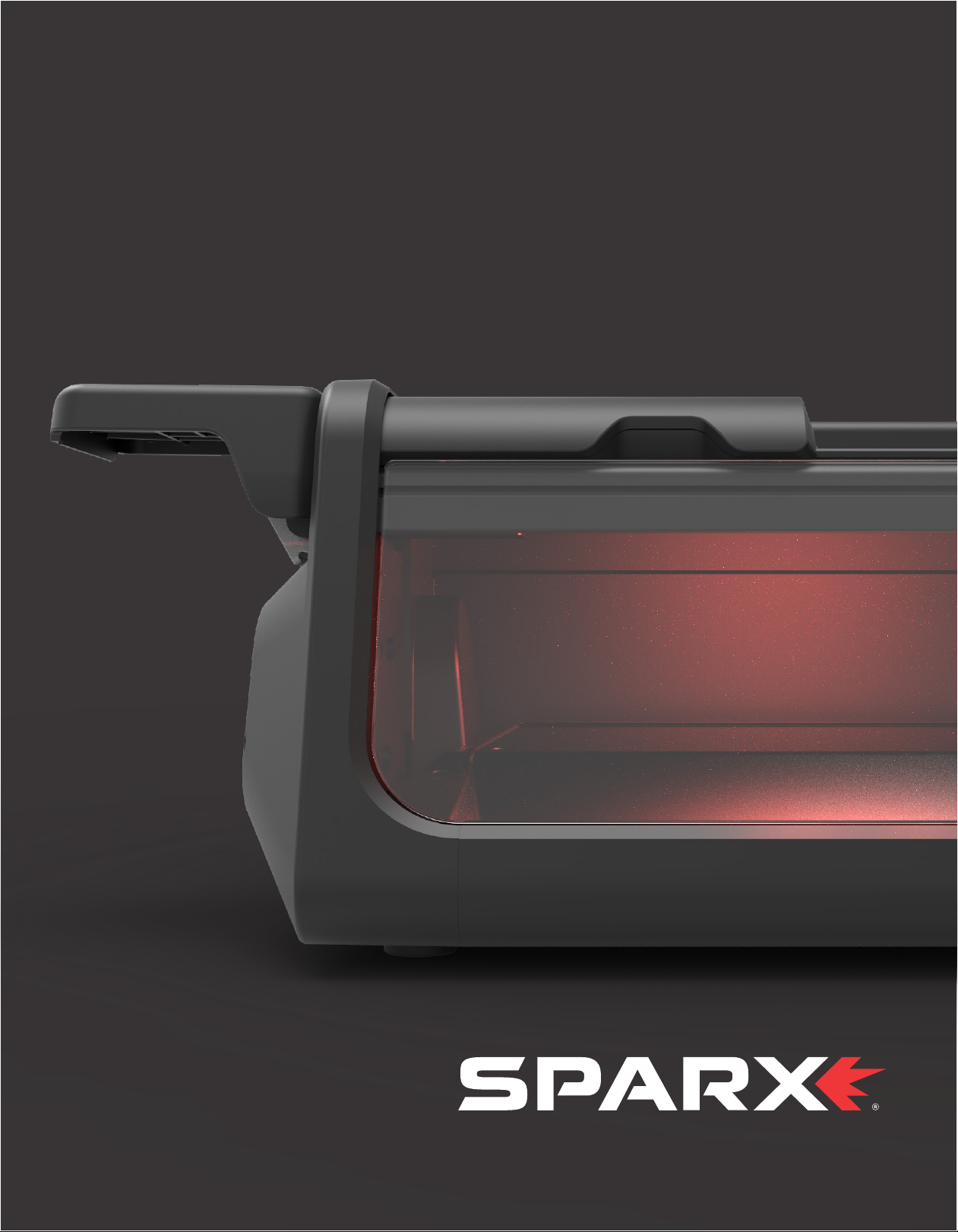
PS100 OPERATING MANUAL
Page 2
Page 3
SAFETY 1
Safety Precautions 1
FCC Notice (for U.S. Customers) 2
Industry Canada Compliance 2
SÉCURITÉ 3
Consignes de sécurité 3
Conformité aux normes d’Industrie Canada 4
INTRODUCTION 5
Technical Specifications 5
Getting to Know Your Sparx Sharpener 6
What’s In the Box? 7
Getting to Know the Keypad 8
Grinding Ring Life Indicator Behavior 9
SETUP 11
Assembling the Sharpener 11
Installing the PV100 Vacuum 12
Alignment 12
OPERATION 15
Loading a Skate 15
Adjusting the Grinding Ring Height 16
Selec ting the Number of Cycles 17
Sharpening Skates 18
Unloading a Skate 18
Edge Deburring 19
Powering O 19
Goalie Skates 19
Sharpening New Steel 20
TROUBLESHOOTING 21
Error Types 21
User Interface prompts 22
Error Codes 23
MAINTENANCE 25
Removing and Emptying the Dust Tray 25
Traveling with the Sharpener 26
WARRANTY 27
Page 4

Page 5
1
SAFETY
SAFETY PRECAUTIONS
1. Before operating the Sparx® Skate Sharpener, you should
familiarize yourself with the product and read and understand all
applicable instructions and warnings in this manual.
2. Use personal protective equipment. Always wear eye protection
and a dust mask while operating the sharpener.
3. For emergencies: press the n Cancel Button two times. This will
stop the Grinding Ring in its place. Do not stop the Grinding Ring
unless it is an emergency, as this may damage the skate blade.
4. The Sparx PS 100 is intended for use only by trained personnel
who are familiar with skate sharpening. We do not recommend that
children under 13 years of age be permitted to use the Sparx® Skate
Sharpener.
5. The Sparx® Skate Sharpener is not intended for use by persons
(including children 13 years and over) with reduced physical,
sensory or mental capabilities, or lack of experience and knowledge,
unless they have been given supervision or instruction concerning
use of the Skate Sharpener by a qualified adult.
6. Children should be supervised to ensure that they do not play
with the Sparx® Skate Sharpener.
7. The Sparx ® Skate Sharpener may only be used for sharpening skates .
8. Only Sparx® Grinding Rings may be used with this machine.
9. Do not operate the Sparx PS100 without an external ventilation
source connected.
10. Set up the product securely on a stable surface and in a
protected location. It must be placed where no one can step on
or trip over the Power Cord and where the Power Cord cannot be
damaged.
11. Always use the Sparx® Skate Sharpener in a dry, well-lit and non-
condensing environment. To avoid the risk of electric shock, do not
use the Sparx® Skate Sharpener in wet or damp conditions.
12. To avoid injury, always use caution when operating the Sparx®
Skate Sharpener or when changing the Grinding Ring.
13. Do not attempt to touch the Grinding Ring, Carriage, or Skate
Clamp while the Grinding Ring is moving. Wait for the Carriage and
Grinding Ring to come to a complete stop before attempting any
adjustments or Grinding Ring replacement.
14. Make sure that the Thumb Nut is tightened down onto the
Grinding Ring before starting any grinding operation
15. Do not leave the Sparx® Skate Sharpener running unattended.
16. Never disconnect the Power Cord by pulling the wire to
disconnect it from the socket.
17. Store the Sparx® Skate Sharpener in a dr y place, out of the reach
of children.
18. Maintain the sharpener according to the Maintenance section
of this manual. Emptying the Du st Tra y at specified intervals is a
necessary step for performance and safety.
19. If at any time the product does not operate normally, see the
Troubleshooting section of this manual.
20. There are no user-serviceable parts on the sharpener. The
sharpener should only be repaired by a professional Sparx® Hockey
technician, using only original spare parts. Unauthorized repairs
could lead to hazardous conditions for the user and/or void the
warranty.
21. For any further questions about the sharpener, please contact
Sparx® Hockey Suppor t at 1-8 55-SPARXHQ ( 1-855-772-7947) or by
email at [email protected].
Warning: Please see the manual for operating instructions.
Caution: Pinch point hazard. Keep hands, hair and other body parts
clear of the Skate Clamp area.
SAFETY 1
Page 6
FCC NOTICE
(FOR U.S. CUSTOMERS)
This device complies with Part 15 of the FCC Rules:
Operation is subject to the following conditions:
1. This device may not cause harmful interference, and
2. This device must accept any interference received, Including
interference that may cause undesired operation
Changes and Modifications not expressly approved by Velasa
Sports, Inc. can void your authority to operate this equipment under
Federal Communications Commissions rules.
INDUSTRY CANADA
COMPLIANCE
This device complies with Industry Canada license-exempt RSS
standard(s). Operation is subject to the following two conditions:
(1) this device may not cause interference, and (2) this device must
accept any interference, including interference that may cause
undesired operation of the device.
ENVIRONMENTAL PROTECTION
Waste electrical products should not be disposed of with household
waste. Please recycle where facilities exist. Check with your Local
Authority or retailer for recycling advice.
CONFORMITY WITH DIRECTIVES
This product is CE marked to denote conformity with: Low Voltage
Directive 2014/35/EC, EMC Directive 2014/30/EU, RoHS Directive
2015/863, Radio Equipment Directive 2014/53/EU, WEEE Directive
2012 /19/EU
SAFETY2
Page 7
CONSIGNES DE SÉCURITÉ
1. Avant d’utiliser l’aûteuse de patins SparxMC, vous devez vous
familiariser avec le produit et lire et comprendre toutes les
instructions et mises en garde dans ce manuel.
2. Portez un équipement de protection individuelle. Portez toujours
des lunettes de sécurité et un masque anti-poussières lorsque vous
utilisez l ’aûteuse de patins.
3. En cas d’urgence : appuyez deux fois de suite sur le bouton
Annuler (Cancel). Ceci immobilise immédiatement la meule
n
d’aûtage. N’arrêtez la meule d’aûtage qu’en cas d’urgence, car
cela pourrait endommager la lame du patin.
4. L’aûteuse de patins SparxPS100 doit être uniquement utilisée
par du personnel qualifié, formé à l’aûtage de patins. Nous
déconseillons d’autoriser les enfants de moins de 13ans à utiliser
l’aûteuse de patins Spar xMC.
5. L’aûteuse de patins SparxMC ne doit pas être utilisée par des
personnes (y compris des enfants de 13 ans et plus) ayant des
capacités physiques, sensorielles ou mentales réduites, ou un
manque d’expérience et de connaissances, à moins qu’elles
soient surveillées ou qu’elles aient reçu une bonne formation sur
l’utilisation de l ’aûteuse par un adulte compétent.
6. Les enfants doivent être surveillés pour s’assurer qu’ils ne jouent
pas avec l’aûteuse de patins SparxMC.
7. L’aûteuse de patins SparxMC doit être utilisée exclusivement pour
l’aûtage de patins.
8. La machine doit être utilisée exclusivement avec des meules
d’aûtage SparxMC.
9. N’utilisez pas l’aûteuse SparxPS100 sans y avoir branché un
dispositif de ventilation externe.
10. Pour assurer la sécurité de tout le monde, installez la machine
sur une surface stable et dans un endroit protégé. Elle doit être
placée dans un endroit où il n’y a aucun risque que quelqu’un puisse
marcher ou trébucher sur le cordon d ’alimentation ou le cordon
d’alimentation puisse être endommagé.
11. Utilisez l’a ûteuse de patins SparxMC toujours dans un
environnement sec, bien éclairé, et sans condensation. Pour éviter
tout risque de décharge électrique, n’utilisez jamais l’aûteuse de
patins SparxMC dans des conditions humides ou mouillées.
12. Pour éviter les blessures, soyez toujours prudent lors
de l’utilisation de l’aûteuse de patins SparxMC, ou lors du
1
SÉCURITÉ
remplacement de la meule d’aûtage.
13. N’essayez pas de toucher la meule d’aûtage, le guide-meule
mobile ou la pince de serrage pendant la rotation et le mouvement
de la me ule . Attendez l’arrêt complet du guide-meule et de la meule
d’aûtage avant de tenter un réglage ou le remplacement de la meule.
14. Assurez-vous que l’écrou à ailettes est serré sur la meule
d’aûtage avant de commencer l’aûtage
15. Ne laissez jamais l’aûteuse de patins SparxMC sans surveillance
pendant qu’elle est en marche.
16. Ne débranchez jamais le cordon d’alimentation en tirant sur le
cordon.
17. Rangez l’a ûteuse de patins SparxMC dans un endroit sec, hors de
la portée des enfants.
18. Réalisez l’entretien de l’aûteuse en suivant les instructions de la
section «Entretien» de ce manuel. Il est nécessaire de vider le bac à
poussière régulièrement pour assurer la performance et la sécurité
de l’appareil.
19. Si, à tout moment, la machine cesse de fonctionner normalement,
consultez la section Diagnostic des pannes de ce manuel.
20. L’aûteuse ne comporte aucune pièce réparable par l’utilisateur.
Elle ne doit être réparée que par un technicien professionnel SparxMC
Hockey, exclusivement avec des pièces de rechange d’origine.
Les réparations non autorisées pourraient créer des conditions
dangereuses pour l’utilisateur ou annuler la garantie.
21. Pour toute question au sujet de l’aûteuse, veuillez communiquer
avec le service technique de SparxMC Hockey au (855-772-7947) ou
par courriel à [email protected].
Mise en garde : Veuillez consulter les instructions dans le manuel.
Attention : Danger de pincement. Gardez les mains, les cheveux et
d’autres parties du corps à l’écart de la zone de la pince de serrage.
SÉCURITÉ 3
Page 8

CONFORMITÉ AUX NORMES
D’INDUSTRIE CANADA
Le présent appareil est conforme aux CNR d’Industrie Canada
applicables aux appareils radio exempts de licence. L’exploitation
est autorisée aux deux conditions suivantes : (1) l’appareil ne doit
pas produire de brouillage, et (2) l’utilisateur de l’appareil doit
accepter tout brouillage radioélectrique subi, même si le brouillage
est susceptible d ’en compromettre le fonctionnement.
SÉCURITÉ4
Page 9

2
INTRODUCTION
TECHNICAL SPECIFICATIONS
SK AT E C O M PATIB I L I T Y
Hockey Skates
Goalie Skates
Figure Skates*
*Requires an additional adapter, which is sold separately.
DIMENSIONS AND WEIGHT
Width: 26.8 Inches / 68 0 mm
Height: 7.6 Inches / 194 mm
Depth: 15.5 Inches / 390 mm
Weight: 38.5 Pounds / 17.5 kg
ELECTRICAL
Line Voltage: 100 –240 Volts AC (50 –60 Hz single phase)
Maximum Power Consumption: 200 W
INTRODUCTION 5
Page 10
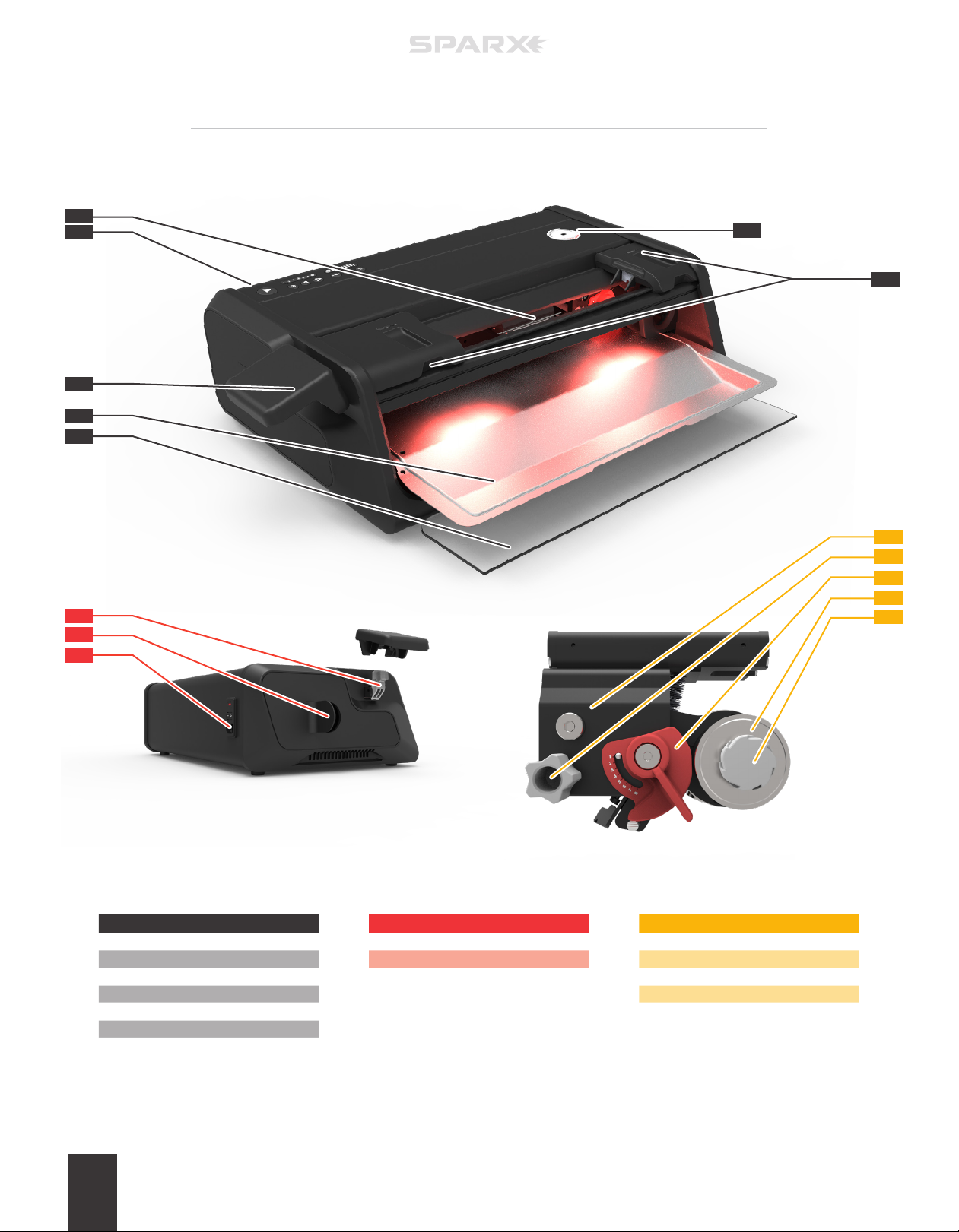
GETTING TO KNOW YOUR SPARX SHARPENER
A
B
F
G
C
D
E
K
L
M
N
G
O
H
J
PART DESCRIPTION
A
Skate Clamp
B
Keypad
C
Clamp L ever
D
Du st Tray
E
Glass Door
F
Travel Screw Slot
G
Protec tive Slot C overs
INTRODUCTION6
PART DESCRIPTION
G
Lever Dock
H
Exhaust Port
J
Power In put Por t
PART DESCRIPTION
K
Carriage
L
Alignment Adjustment Knob
M
Height Adjustment Knob
N
Grinding Ring Shaft
O
Thumb Nut
Page 11
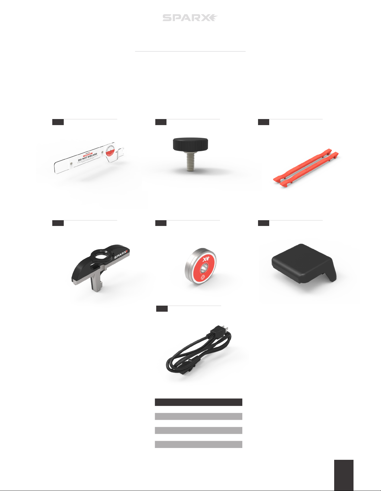
WHAT’S IN THE BOX?
1
4
2
5
3
6
7
PART DESCRIPTION
1
Trav el Gu ar d
2
Trav el Screw
3
Goalie Risers (2)
4
Optic al Alignment Tool
5
Alignment Ring
6
Clamp L ever
7
Power Cord
INTRODUCTION 7
Page 12
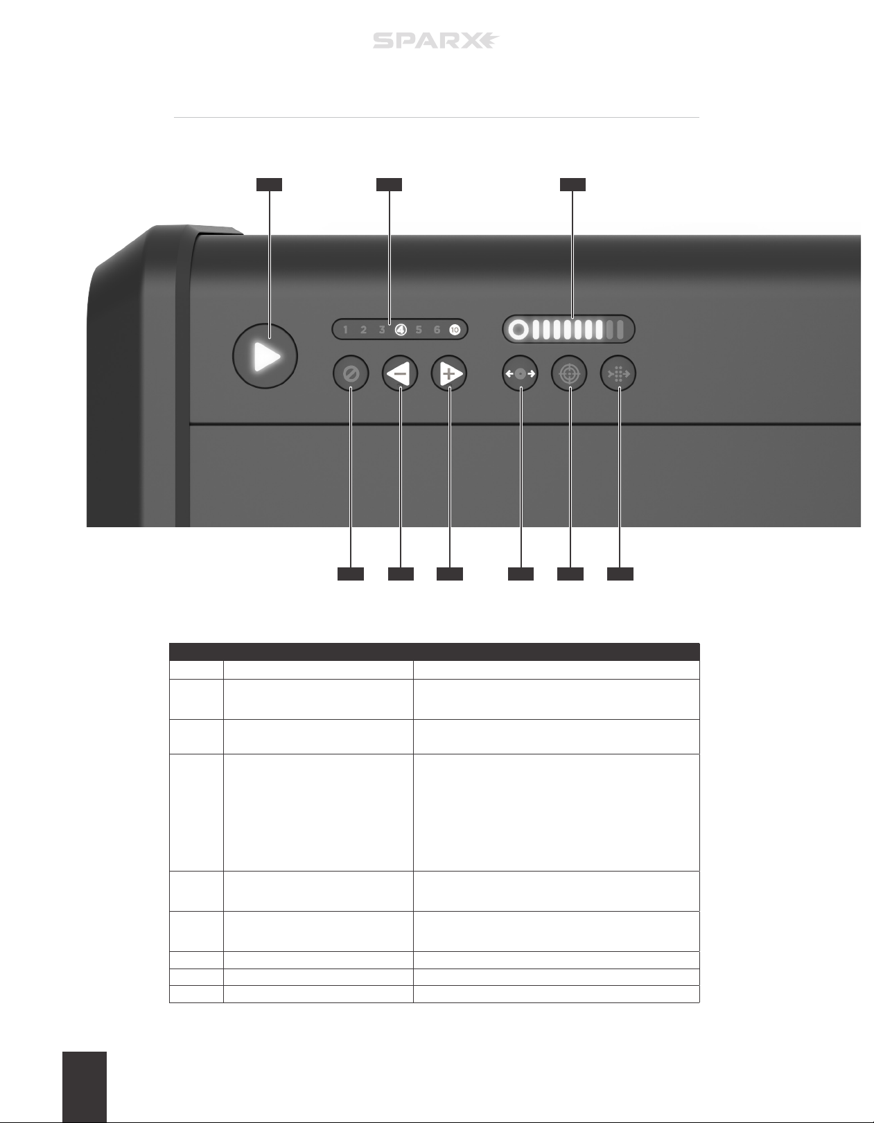
GETTING TO KNOW THE KEYPAD
A
B C
D E F G H J
PART BUTTON DESCRIPTION
A Play
B Cycle Counter
C G rindi ng Ring Li fe Indicator
D Cance l / Error
E Minus Cycles / Move Left
F Add C ycles / Move Right
G Move
H Alignment
J Filter
Initiates the sharpening.
• Shows the current number of cycles selected.
• Shows error codes.
Indicates Grinding Ring life status. See Grinding Ring
Life Indicator Behavior table on page 9.
• Push 1 time to stop the Carriage at the conclusion of
the current pass.
• Push 2 times for emergency stop, motor stops
immediately.
• When illuminated red, the sharpener is in an error
state, see Troubleshooting section of manual.
• Subtracts cycles from the Cycle Counter.
• If in Move Mode, moves Carriage to the left.
• Adds cycles from the Cycle Counter.
• If in Move Mode, moves Carriage to the right.
Initiates Move Mode.
Initiates Alignment Mode.
Indicates External Vacuum power needed.
INTRODUCTION8
Page 13
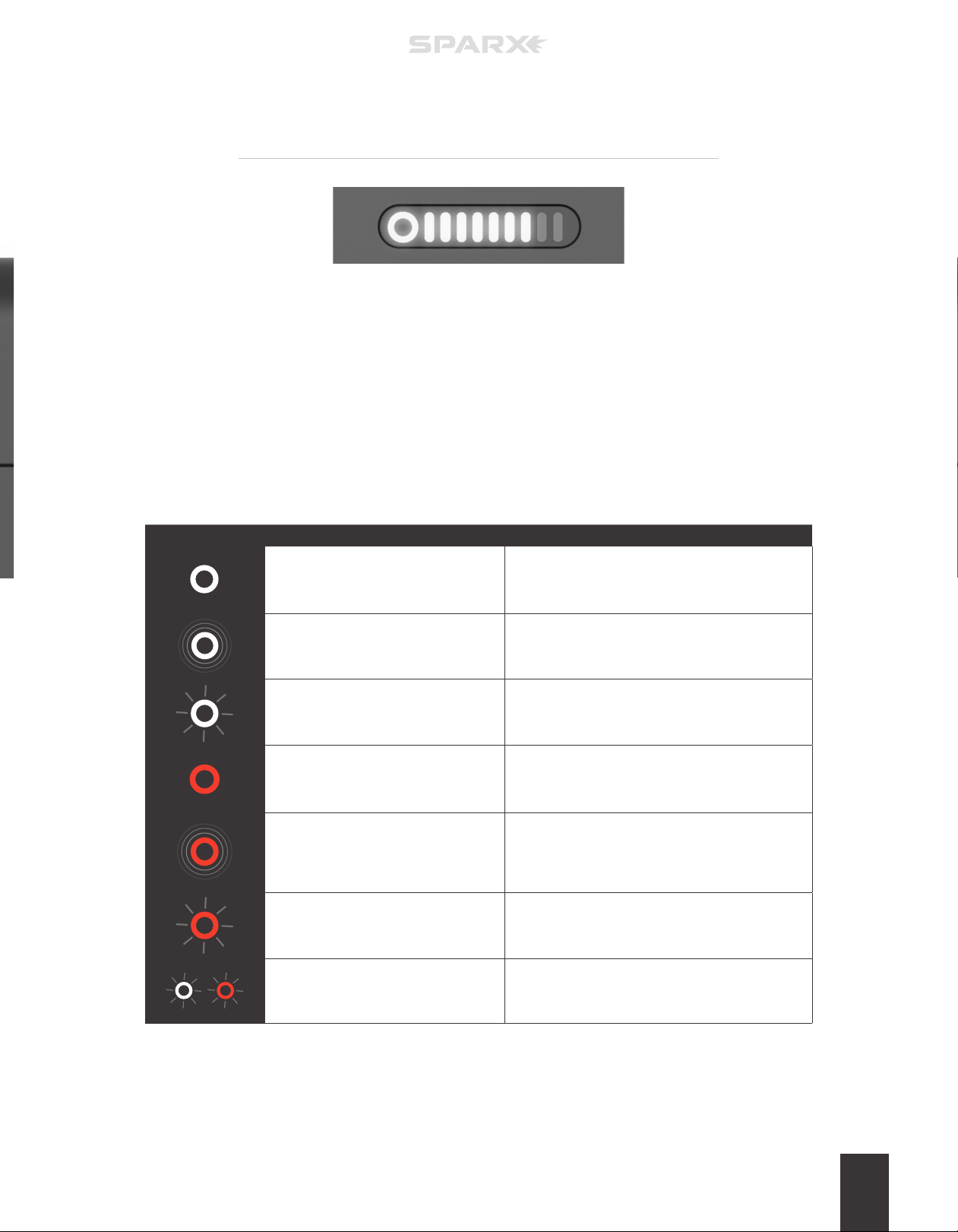
GRINDING RING LIFE
INDICATOR BEHAVIOR
In normal operation, each part of the Grinding Ring Life Indicator corresponds to 10% of
the Grinding Ring’s life. These parts are the one circle and the nine bars to the right (10
parts total or 100%). The circle represents the final 10% of Grinding Ring life and each
bar to the right is an additional 10%. When a par t is illuminated, that corresponding 10%
life is present on the Grinding Ring. When the part is no longer illuminated that amount
of the wheel life has been consumed.
The circle of the Grinding Ring Life Indicator can also behave in other ways to indicate
dierent operating conditions to the user. Refer to the table below for more information.
ICON ACTION DESCRIPTION
Circle is white and steady.
Circle is white and pulsing.
Circle is white and blinking.
Circle is red and steady. No Grinding Ring installed.
Circle is red and pulsing.
Circle is red and blinking. Grinding Ring is Em pty.
Circle half red/half white - alternate
blinking.
The Grinding Ring has more than 10% of life
remaining.
Grinding Ring has less than 10% of life remaining.
We Recommend that the user order a replacement
Grinding Ring by visiting www.sparxhockey.com.
User has attempted to start Alignment Mode while a
Grinding Ring is installed.
During sharpening, the Grinding Ring has less than
10% of life remaining. We Recommend that the user
order a replacement Grinding Ring by visiting www.
sparxhockey.com.
User has attempted to sharpen with a cycle count
greater than the number of cycles remaining on the
Grinding Ring.
INTRODUCTION 9
Page 14

Page 15
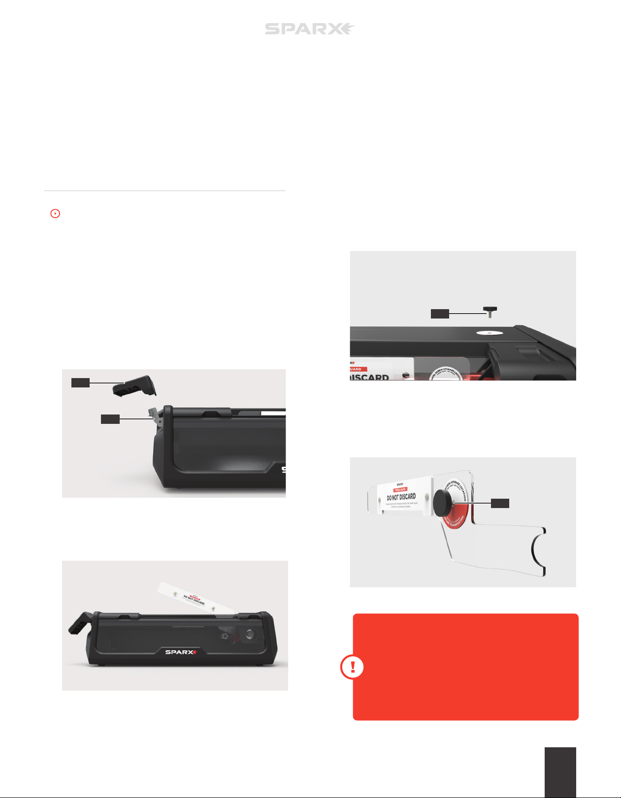
ASSEMBLING THE SHARPENER
To watch the How-To video, visit sparxhockey.com/assembly.
1 PLACE SHARPENER
Place the sharpener on a sturdy, level surface. Locate the
sharpener so that the vacuum hose can be connected easily
from the sharpener to the vacuum system.
3
SETUP
keep t
4 REMOVE THE TRAVEL SCREW
Remove the Travel Screw (A) by turning counter-clockwise until
loose.
2 INSTALL THE CLAMP LEVER
Slide the Clamp Lever (A) onto the Lever Dock (B). Press the
lever down until it clicks into place. When the Clamp Lever is
engaged, it will lay at a slight angle.
A
B
3 REMOVE THE TRAVEL GUARD
Open the Skate Clamp by pressing and holding down the
Clamp Lever. Remove the Travel Guard. Release the Clamp Lever.
A
5 STORING THE TRAVEL SCREW
Install the Travel Screw into the storage loaction on the Travel
Guard (A) by turning clockwise until hand-tight. Do not over-
tighten.
A
Do not discard the Travel Guard. This guard is o
Transporting or moving the Sharpener without
the Travel Guard & Travel Screw installed voids
your Warranty and/or Extended Service Plan.
Always remove the Travel Guard & Travel Screw
before operating the Sparx Sharpener.
SETUP 11
Page 16
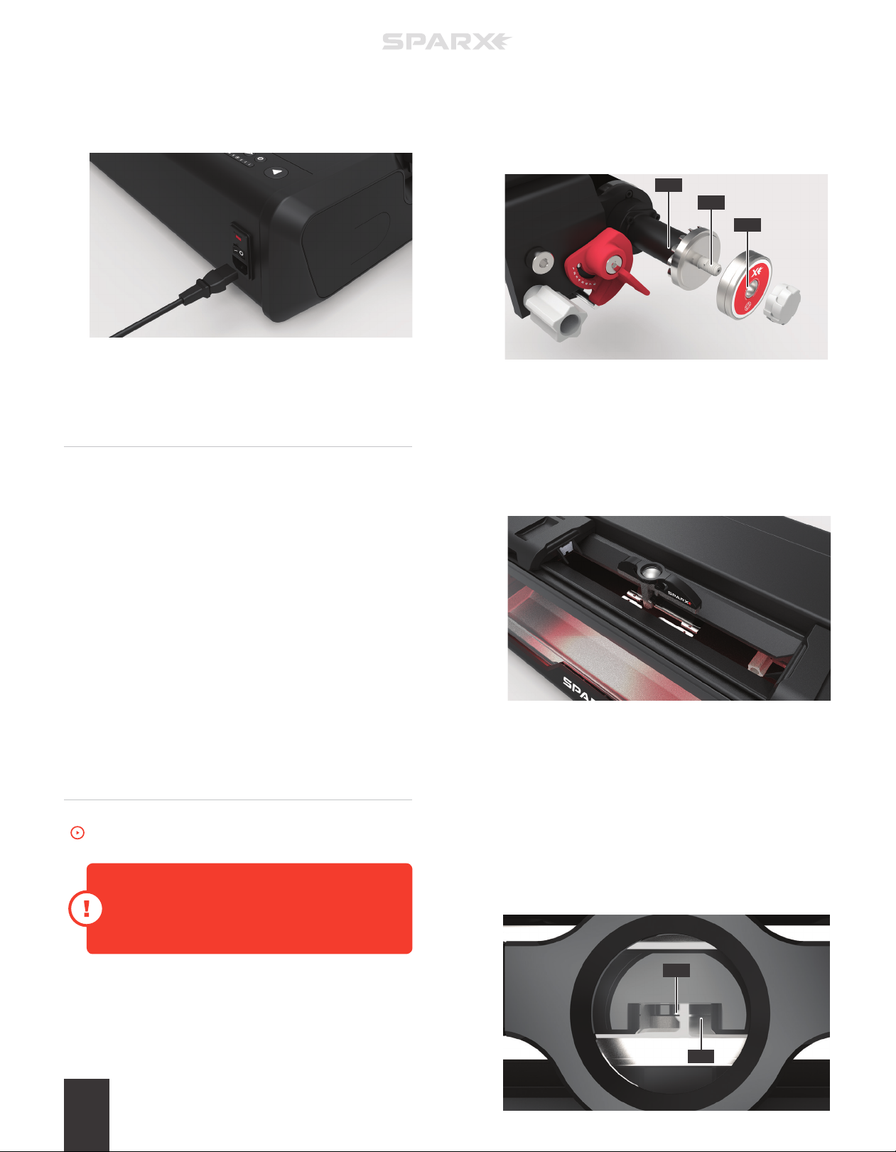
6 PLUG IN THE POWER CORD
Plug the Power Cord into the Power Input Port on the back of
the sharpener. Plug the other end into a wall outlet. Toggle the
switch on the Power Input Port to the on position (I=on, 0=o).
INSTALLING THE
PV100 VACUUM
For installation of the Auto-Switch, see included instructions .
1 CONNECT THE SUCTION HOSE
Install the Vacuum near the sharpener, preferably at floor level,
or under the table that the sharpener is installed on. This is
recommended for noise suppression. Connect the included
Suction Hose directly from the Exhaust Port to one of the
vacuum’s inlet ports.
2 CONNECT THE FOOTSWITCH
If using an accessory Footswitch, connect the power cord for
the Vacuum to the Footswitch and connect the Footswitch
Power Cord to a wall outlet. Ensure that the power switch for
the Vacuum System is turned on. The Footswitch can then be
used to turn the Vacuum on during sharpening, and turn the
Vacuum o when sharpening is complete.
ALIGNMENT
the install position, and the sharpener will play a “ready” tone.
While holding the Grinding Ring Shaft (C), unscrew the Thumb
Nut (A). Slide the Alignment Ring (B) onto the Grinding Ring
Shaft (C), with the label facing out. Replace and tighten the
Thumb Nut until hand-tight. Close the Glass Door.
C
B
A
2 INSTALL THE OPTICAL ALIGNMENT TOOL
Press down on the Clamp Lever to open the Skate Clamp.
Place the Optical Alignment Tool (with Sparx® logo facing
towards the user) into the Skate Clamp and let it fall into place.
Release the Clamp Lever.
3 INITIATE ALIGNMENT MODE
Press the c Alignment Button to send the Carriage to its
alignment position. When the Carriage is in place, a tone will
sound and the case will illuminate blue.
To watch the How-To video, visit sparxhockey.com/alignment.
The Alignment process is required when you first
receive your Sparx® Sharpener and also after every
time the sharpener is moved and/or travels.
1 INSTALL THE ALIGNMENT RING
Open the Glass Door. The Carriage will automatically move into
SETUP12
4 LOCATE THE TAB AND GROOVE
Look through the eyepiece of the Optical Alignment Tool and
locate the indicator tab (A) of the Optical Alignment Tool and
the groove (B) on the Alignment Ring.
A
B
Page 17
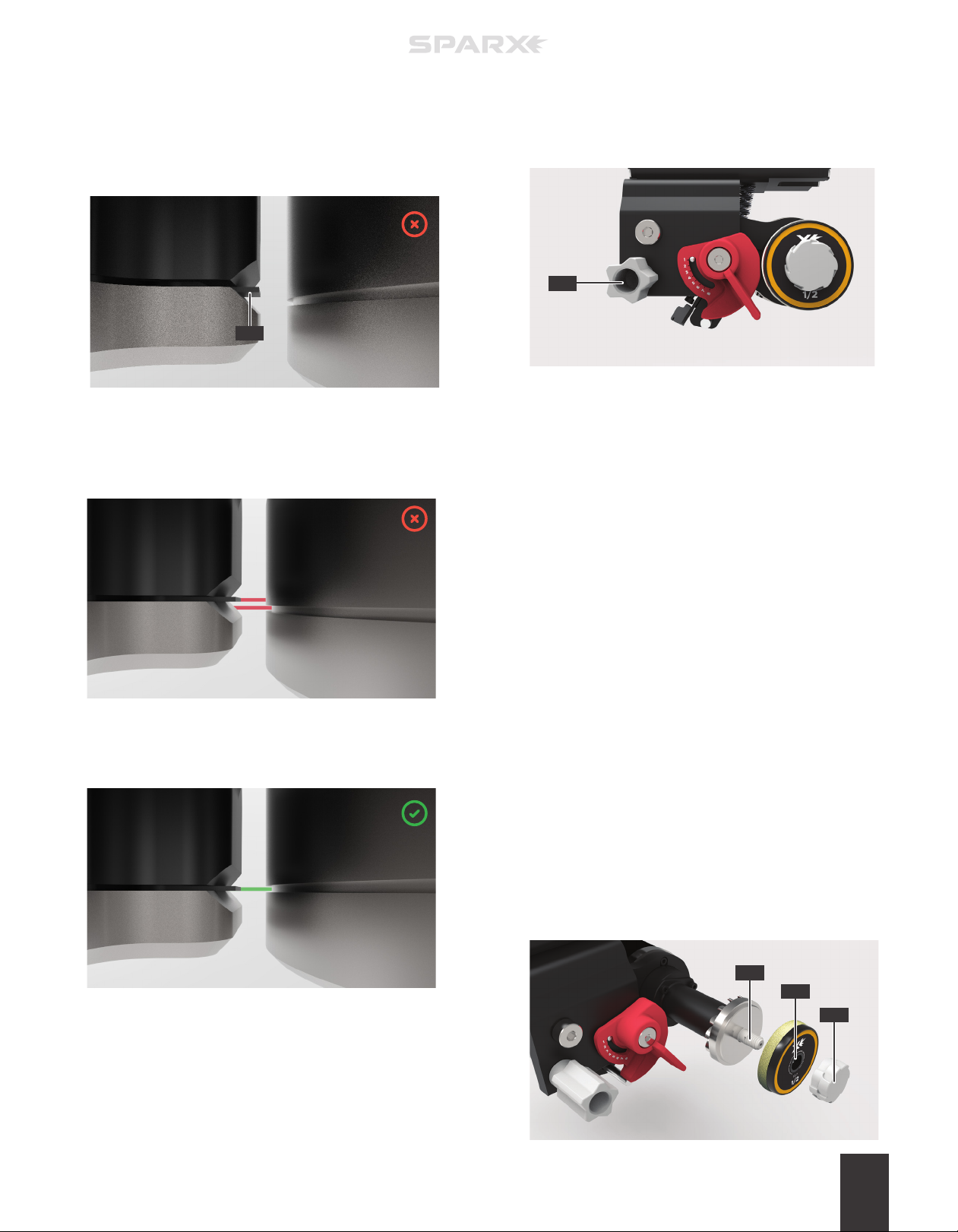
Ensure you are looking straight through the eyepiece directly
above the indicator tab and groove. If you see the indicator tab
side wall (C) when looking through the eyepiece, you are not
directly above the indicator tab and groove. Adjust your line of
sight until you can no longer see the indicator tab side wall.
C
5 INSPECT THE ALIGNMENT
If the indicator tab of the Alignment Tool is not aligned with the
groove on the Alignment Ring (as shown below), move to step 6.
6 LOCATE THE ALIGNMENT
ADJUSTMENT KNOB
Open the Glass Door and locate the gray y Alignment
Adjustment Knob (A) inside of the sharpener.
A
7 ADJUST THE ALIGNMENT
While looking through the O ptical Alignment Tool, turn the
Alignment Adjustment Knob until the groove on the
Alignment Ring (right) lines up with the indicator tab of the
Alignment Tool (left), as shown in step 5. Close the Glass
Door when aligned.
If the indicator tab of the Alignment Tool is aligned with the
groove on the Alignment Ring (as shown below) skip to step 8.
8 END ALIGNMENT MODE
End Alignment Mode by pressing the c Alignment Button.
9 REMOVE THE OPTICAL ALIGNMENT TOOL
Press down on the Clamp Lever to open the Skate Clamp.
Remove the Optical Alignment Tool.
10 REMOVE THE ALIGNMENT RING
Open the Glass Door. The Carriage will automatically move
into the install position and the sharpener will play a “ready”
tone. While holding the Grinding Ring Shaft, unscrew the
Thumb Nut and remove the Alignment Ring.
11 INSTALL THE GRINDING RING
While holding the Grinding Ring Shaft (C), slide the Grinding
Ring (B) on the Grinding Ring Shaft (C), label facing out, and
replace and tighten the Thumb Nut (A) until hand-tight. Close
the Glass Door.
C
B
A
SETUP 13
Page 18

Page 19
4
OPERATION
We recommend inserting the skate into the
Skate Clamp with the toe pointing to the right .
For most skate blades, this orientation allows for
the greatest flexibility in Grinding Ring height
adjustment . It is, however, acceptable to insert
the skate with the toe facing in either direction.
LOADING A SKATE
*For loading goalie skates and youth skates ,
see the end of this section.
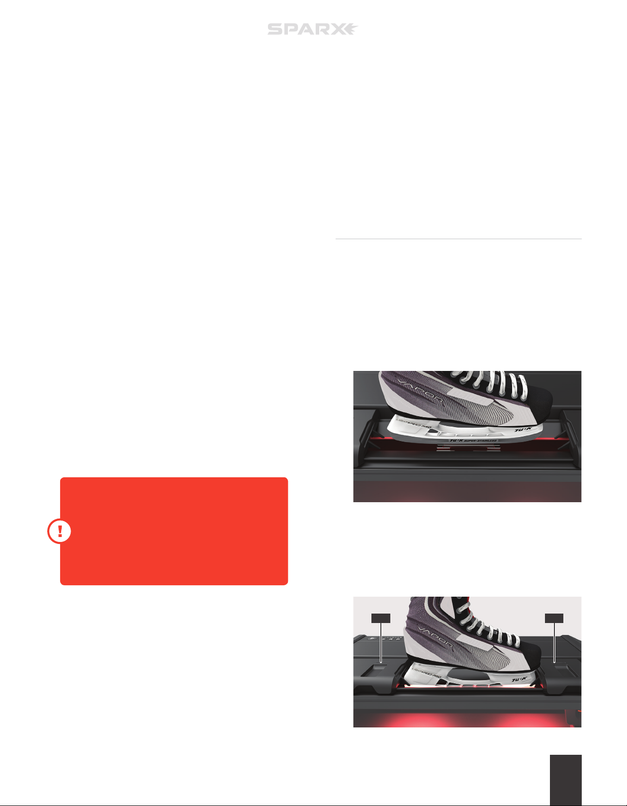
1 LOAD THE SKATE
Press and hold down the Clamp Lever to open the Skate Clamp.
With the skate toe pointing right and the laces tucked into the
skate, set the skate into the Skate Clamp slot letting the plastic
blade holder rest on top of the clamps. Center the skate blade
in the Skate Clamps. Release the Clamp Lever.
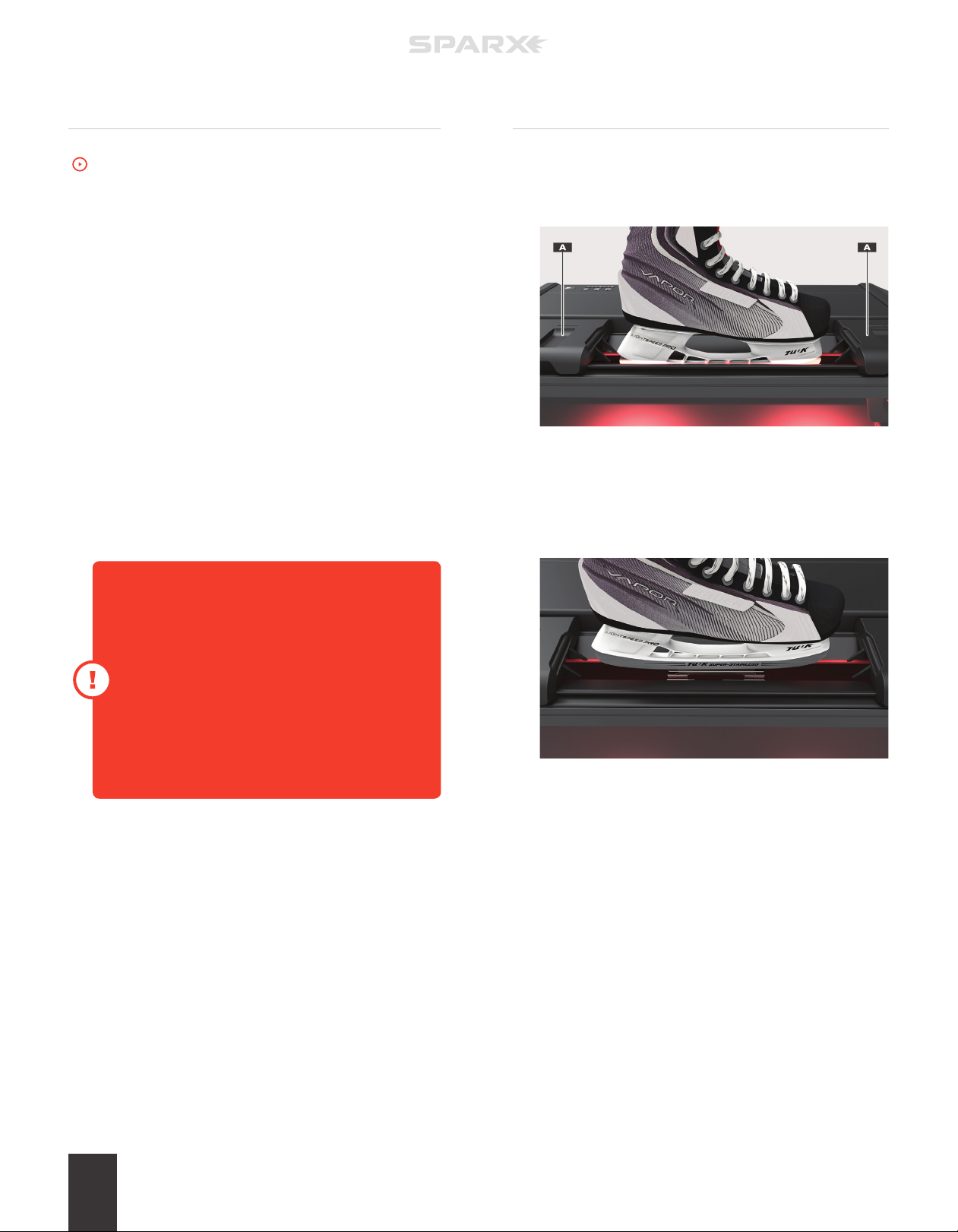
2 CLOSE THE PROTECTIVE SLOT COVERS
Move each Protective Slot Cover (A) in toward the skate to
close the gap between the skate and the cover. Use caution not
to allow the slot cover to exert excessive force on the skate as
this may aect the alignment of the sharpening.
AA
OPERATION 15
Page 20
ADJUSTING THE GRINDING
RING HEIGHT
To watch the How-To video, visit sparxhockey.com/ringheight.
For every pair of skates sharpened, you must
assess the height of the Grinding Ring and adjust
if necessary.
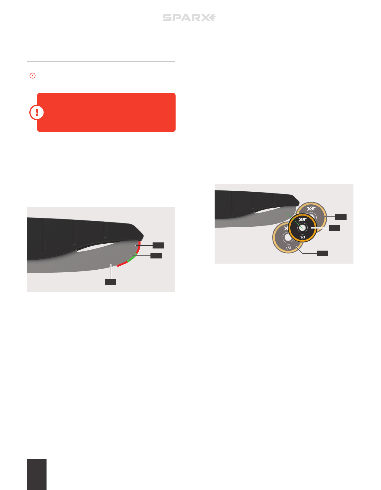
We will first introduce a few new concepts, and then move into the
actual adjustment. We want to define an intersection zone, where
the vertical face of the blade (B) meets the nearly horizontal face of
the blade (C).
This zone can be a cur ved section of blade (A) like that shown in the
figure below or in some cases , it can be a point where surfaces (B)
and (C) meet.
1 INITIATE MOVE MODE
Press the m Move Button on the Keypad. This will set the
Grinding Ring into Move Mode and allow you to control
its movement.
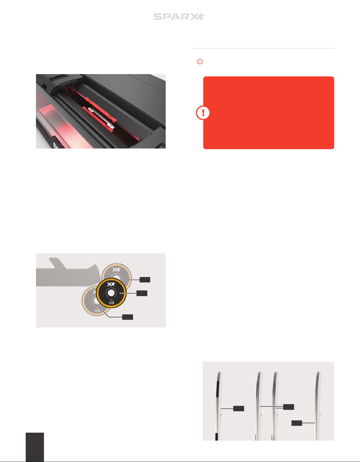
2 INSPECT THE CONTACT POINT
Use the l Left and r Right Buttons to touch the Grinding
Ring to the skate blade. Inspect its contact point and be sure
it is in the desired position. In the graphic below you will see
an example of a contact point that correctly set (A), too high
(B), and too low (C). Another way to help visualize the correct
contact point would be drawing an imaginary line (green
dashed line in the example below) from the center of the
Grinding Ring to the initial contact point, the line should be at a
45 degree angle. If the Grinding Ring is not in a desired position,
follow step 3. If the Grinding Ring is in a desired position, skip
to step 6.
B
B
A
C
When the intersection zone is a curved surface (A as shown above)
the Grinding Ring can safely initially contact the blade anywhere in
this region (A).
When the intersection zone is a point, which is more common with
skates that have been sharpened multiples times, the first contact
between the Grinding Ring and the blade should be just below the
point.
A
C
OPERATION16
Page 21
3 MOVE THE CARRIAGE INTO POSITION
Using the l Left and r Right Buttons on the Keypad, back
the Grinding Ring o the toe of the skate blade 1/4 inch.
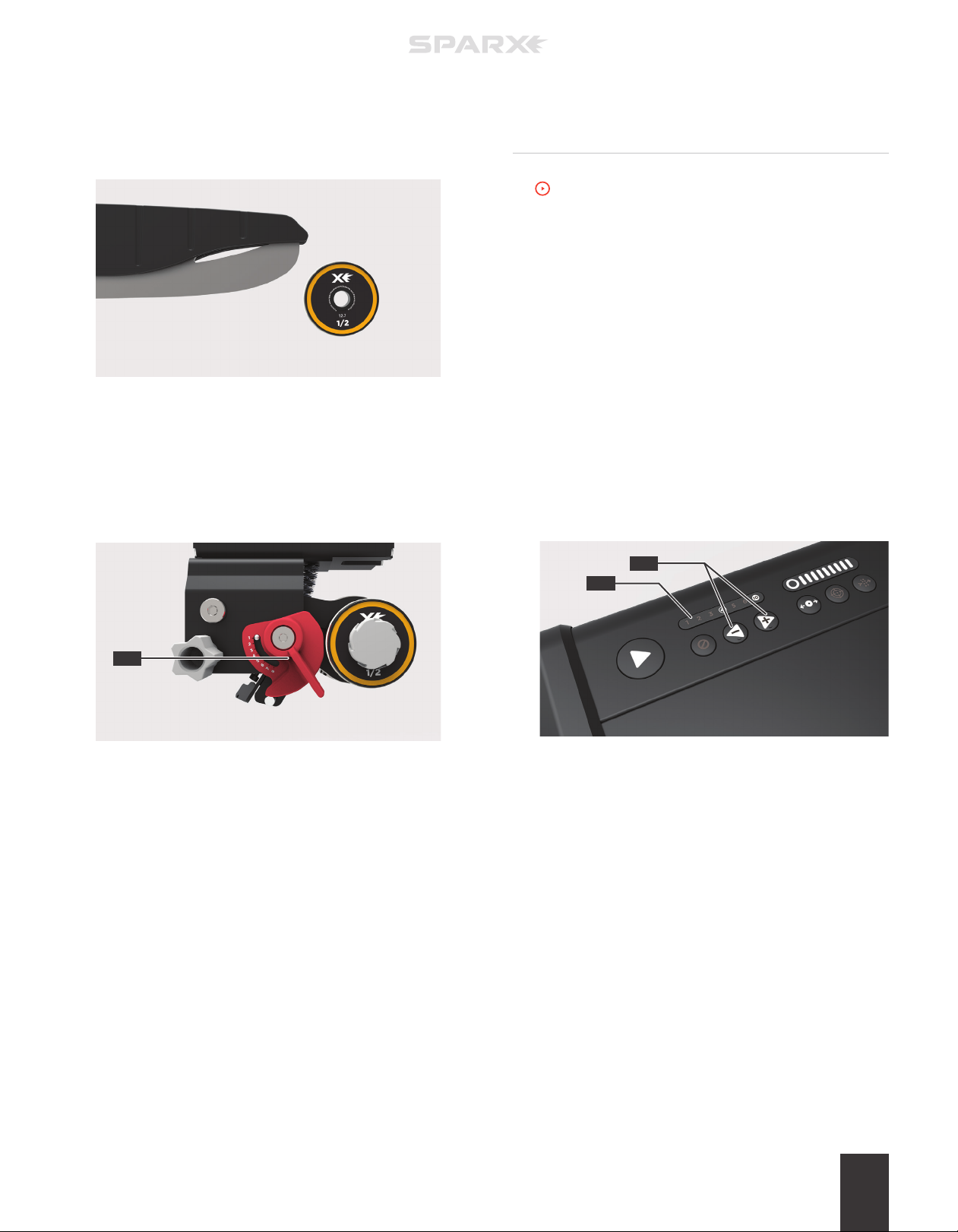
4 ADJUST THE GRINDING RING HEIGHT
Open the Glass Door. Locate the red h Height Adjustment
Knob (A). Turn the knob left to raise the height or right to
lower the height until the Grinding Ring is at the desired height.
The knob is labeled 1-8 , with 8 being the highest setting for the
Grinding Ring and 1 being the lowest setting.
SELECTING THE NUMBER
OF CYCLES
To watch the How-To video, visit sparxhockey.com/cycle.
When the sharpener moves the Grinding Ring out and back over the
skate blade once, it is called a cycle.
The Sparx® Sharpener comes set automatically to a standard 4
four cycles with all standard Radius Ring® and FIRE Ring® Grinding
Rings. We recommend trying four cycles to start and moving higher
or lower as needed. Typically, four cycles will handle normal wear
and tear (and even small nicks) from one to four hours of skating
between sharpenings . For New Steel, refer to “ Sharpening New
Steel” at the end of this Operation section.
1 ADJUST THE CYCLE COUNT
Use the l Left and r Right Buttons (A) on the Keypad to
adjust the number of cycles desired. The number of cycles
selected will be illuminated on the Cycle Counter (B).
A
5 INSPECT THE CONTACT POINT
Close the Glass Door. Once the Glass Door has been closed,
using the l Left and r Right Buttons, touch the Grinding Ring
to the skate blade. Inspect its contact point and be sure it is
in its desired position. Repeat steps 4 and 5 until the Grinding
Ring makes contact at the desired position.
6 END MOVE MODE
Press the m Move Button again to send the Grinding Ring back
to its home position .
A
B
OPERATION 17
Page 22
SHARPENING SKATES
UNLOADING A SKATE
To watch the How-To video, visit sparxhockey.com/sharpening.
Once you have loaded the skate, closed the Protective Slot Covers,
and adjusted the height of the Grinding Ring, you are ready to begin
sharpening.
To cancel the cycles at any point during the sharpening, press the
Cancel Button once. This will send the Carriage back to its home
n
position at the end of its current pass.
1 TURN ON PV100 VACUUM SYSTEM
If using an accessory Footswitch, press down on the pedal to
power on the external ventilation during sharpening.
2 BEGIN SHARPENING
Press the p Play Button. Once the button has been pressed, it
will change from white to blue and the sharpening process will
begin.
If the Grinding Ring skips, comes to a halt, or
your sharpener suddenly powers o when it
first makes contact with the blade, the Grinding
Ring’s height is too high. When properly set, the
Grinding Ring should make a smooth transition
onto the skate blade.
For guidance selecting a proper Grinding Ring
height, refer back to “Adjusting the Grinding Ring
Height” earlier in this Operation section.
1 DISENGAGE PROTECTIVE SLOT COVERS
Move both Protective Slot Covers (A) away from the skate.
2 REMOVE THE SKATE
Press and hold down the Clamp Lever to open the Skate
Clamp. Remove the skate from the Skate Clamp and release the
Clamp Lever.
Upon pressing the p Play Button, the Cycle Counter will flash with
the current cycle number until that cycle (out and in) is completed.
The sharpener will continue to run until all cycles have been
performed.
At the completion of the final cycle, the end of sharpening is marked
by a “cycle complete” tone and the case LEDs will turn green.
ADDITIONAL CYCLES
If additional cycles are desired, you can reset the cycle count and
press the p Play Button again.
OPERATION18
Page 23
EDGE DEBURRING
To watch the How-To video, visit sparxhockey.com/deburr.
4 REPEAT ON THE OPPOSITE SIDE
Turn the skate over. Repeat step 3 on the opposite edge of
the blade.
We recommend using protective gloves when
deburring the skate blade.
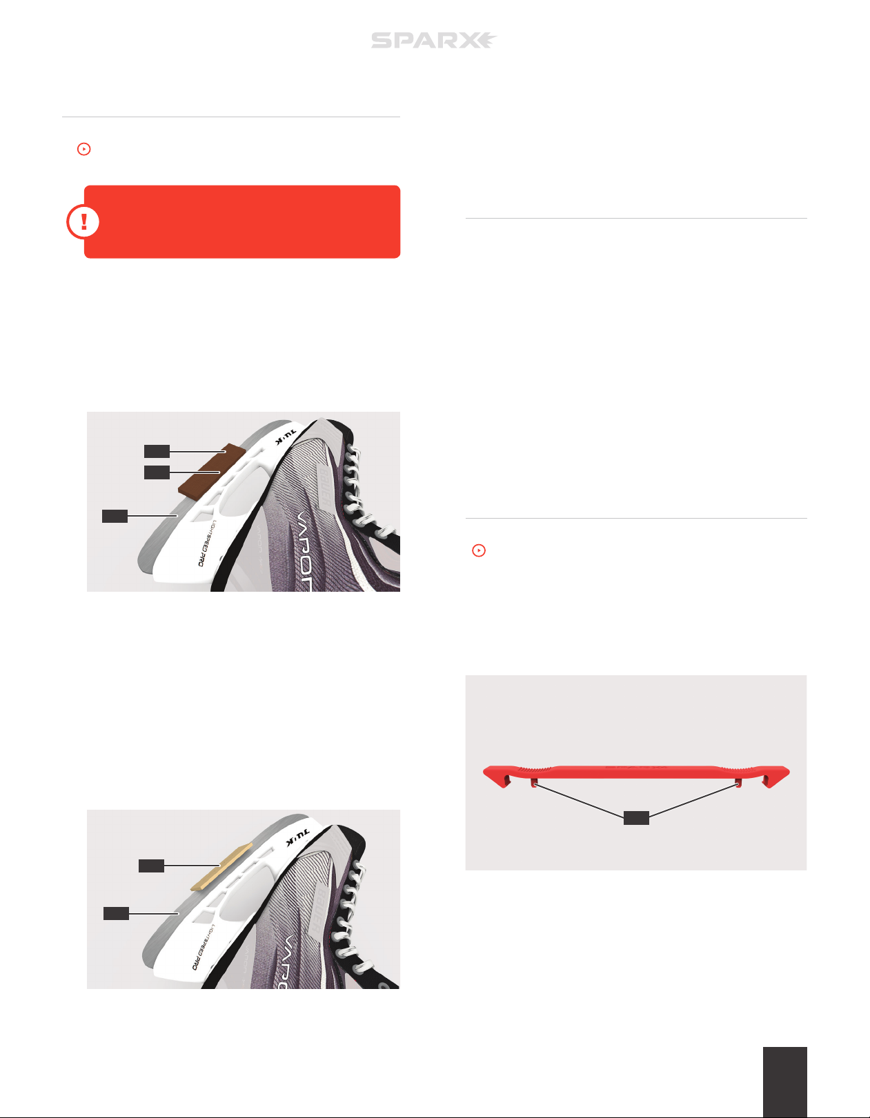
1 DEBURR THE BLADE WITH THE STONE
Press the Honing Stone (A) against the face of the skate blade
(B). Do not put pressure on the side of the stone closest to the
blade edge. With light pressure, press down on the lower side
of the stone (C) and slowly run the stone back and forth along
the length of the blade for four full passes.
A
C
B
2 REPEAT ON THE OPPOSITE SIDE
Turn the skate over. Repeat step 1 on the opposite side of
the blade.
POWERING OFF
1 LOCATE THE POWER INPUT PORT
On the back of the sharpener, locate the Power Input Port.
2 TURN OFF THE SHARPENER
Toggle the Power Input Port switch to the o position (I=on,
0=o).
3 TURN OFF PV100 VACUUM SYSTEM
If using an accessory Footswitch, press down on the pedal to
power o the external ventilation during sharpening.
GOALI E SKATES
To watch the How-To video, visit sparxhockey.com/loadgoalie.
Before loading a goalie skate, you must first install the Goalie
Risers onto the Skate Clamp (o ne Goalie Riser on each side of the
Skate Clamp). Each Goalie Riser has two Anchor Pins (A) as shown
below.
3 DEBURR THE BLADE WITH THE STROP
Press the Leather Strop (A) against the edge of the skate blade
(B) at a 45 degree angle. With light pressure, slowly run the
strop back and forth along the length of the edge for four full
passes
A
B
A
OPERATION 19
Page 24
1 INSTALL THE GOALIE RISERS
Align the Anchor Pins of the Goalie Risers to the Anchor Slots
of the Skate Clamp. Once aligned, press down firmly until you
feel the Goalie Risers snap into place.
2 CONTINUE THE SHARPENING PROCESS
Refer to “Loading a Skate” in the Operation section of the
manual. When adjusting the Grinding Ring Height, refer the
graphic in step 3.
3 ADJUST THE GRINDING RING HEIGHT
Refer to “Adjusting the Grinding Ring Height” in the Operation
section of the manual using the figure below as your guide
where the desired contact point is A, contact point B is too
high and contact point C is too low.
SHARPENING NEW STEEL
To watch the How-To video, visit sparxhockey.com/newsteel.
Before loading new steel, take a dark colored
marker and fill in three strips (1 inch in length
the full width of the blade) on the toe, heel, and
middle of the bottom surface of the skate blade.
To ensure you have sharpened the entire blade,
inspect the blade after running the cycles and if
the sharpening is complete, all of the marker on
the skating surface will be removed.
1 LOAD THE SKATE
After applying the marker (A in the below example), follow the
instructions in “Loading a Skate” in the Operation section of
this manual.
2 ADJUST GRINDING RING HEIGHT
Follow the instructions in “Adjust the Grinding Ring Height ” in
the Operation section of this manual.
3 SELECT 1 CYCLES
Using the l Left and r Right Buttons, select 1 on the
Cycle Counter.
B
A
C
4 CONTINUE THE SHARPENING PROCESS
Refer to “Sharpening Skates” in the Operation section
of the manual.
5 REMOVE THE GOALIE RISERS
Pull up on each end of the Goalie Risers to remove from the
Skate Clamp.
4 CONTINUE THE SHARPENING PROCESS
Refer to the Operation section of the manual.
5 INSPECT BLADE SURFACE
If the marker is gone (C in the example below), you have
successfully set your edges. If there is still marker left on the
blade (B), continue running cycles until it is completely gone.
Due to variations in blade thickness, steel quality, and edge
height dierence, some new steel may require fewer than 10
cycles, and some more. If you are using our XG Grinding Rings,
the cycle count will be lower.
A
B
C
OPERATION20
Page 25
TROUBLESHOOTING
ERROR TYPES
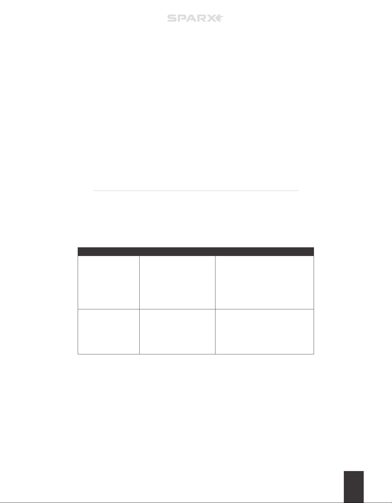
There are two types of errors encountered by the Sparx® Sharpener that can interrupt
ope ration. These types are: Function Entry errors and System Stop errors. Each error type is
described in the table below along with information about how the user is informed of the error.
ERROR TYPE DESCRIPTION DISPLAY METHOD
• Displayed through the user interface
(e.g. flashing lights at the area of
I: Function Entry
II: System Stop
Errors that prevent the user
from entering into a function
(e.g. sharpening or alignment).
Errors that cause the sharpener
to exit out of a function
because of safety concerns or
to prevent sharpener damage.
concern).
• Temporarily displayed on the Cycle
Counter.
• Not saved to Error History.
• Displayed on the Cycle Counter.
• All functionality is disabled until the user
acknowledges the error by pressing the
Cancel Button.
n
• Saved to Error History.
5
TROUBLESHOOTING 21
Page 26
USER INTERFACE PROMPTS
If you are attempting to sharpen a skate, go into Alignment Mode, or go into Move Mode,
but the sharpener is not allowing it, the sharpener will temporarily display an interface
prompt, show an error code, and sound an “error” tone.
The most common Interface prompts are listed in the table for interface prompts below. If
the user interface prompt is unclear or only an error code is displaying, refer to the Error
Code table on the next page.
ACTION CAUSE CORRECTIVE ACTION
Interior case light is blinking red. D ust Tray is missing. Reinstall Dust Tray.
Grinding Ring Life Indicator
circle is blinking red/white.
Grinding Ring Life Indicator
circle is blinking red.
In the event that an error cannot be resolved, please contact customer support at Sparx Hockey.
Grinding Ring has insucient
life remaining for selected
sharpening operation.
Grinding Ring not found. /
Grinding Ring empty.
Sharpener will reset Cycle Count to maximum available
cycles, run sharpener with the new value or lower.
Install a valid Grinding Ring.
SPARX HOCKEY CUSTOMER SUPPORT
[email protected] (fastest response)
1-855-SPAR X HQ (1-855-772-7947)
TROUBLESHOOTING22
Page 27
ERROR CODES
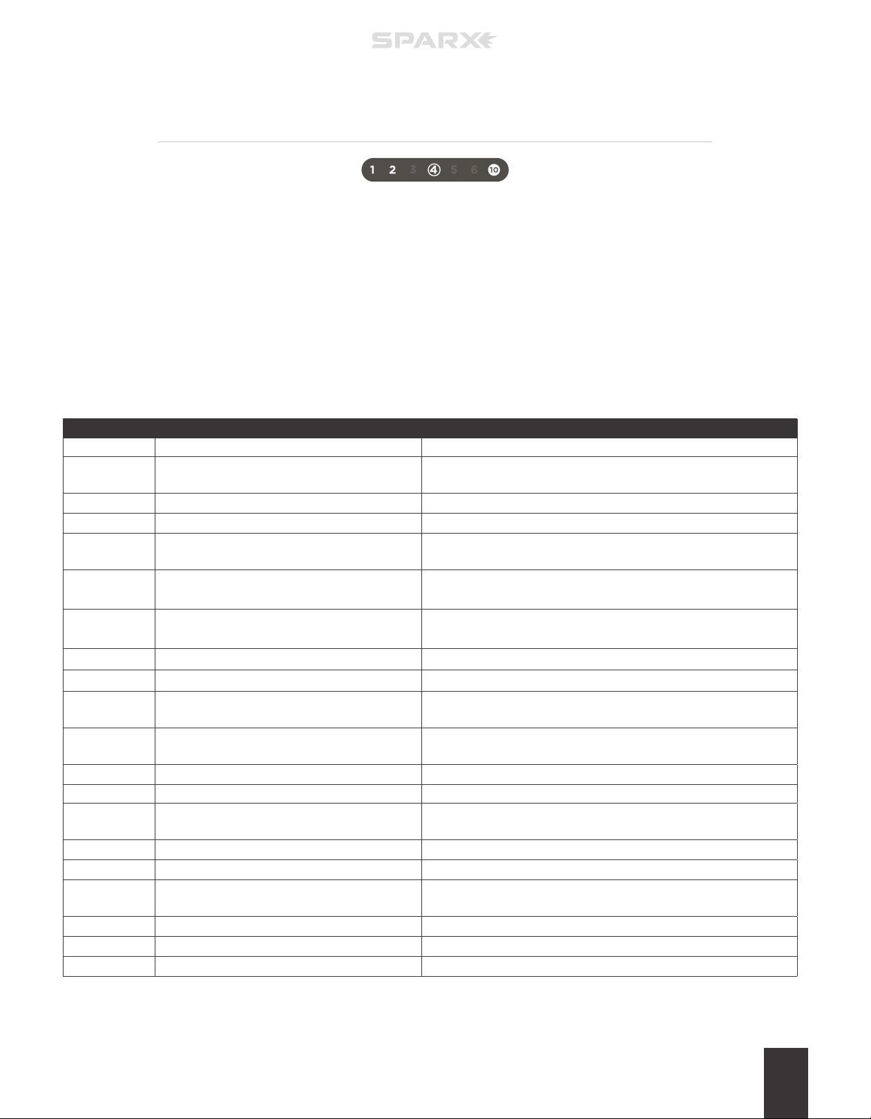
For all errors, an error code is displayed on the Cycle Counter ( 1-2-4 is being displayed in the figure above),
these error codes will either be permanently or temporarily displayed. If an error code was temporarily
displayed and you want to see it again, retrying the action without fixing the underlying cause will display the
error. Permanent errors codes require the user to acknowledge the error before the error will be resolved and
operation can continue. Permanent Error Codes will also be stored in the Error History (discussed below). The
troubleshooting table below suggests corrective actions to resolve the error.
If the user wishes to cycle through previous permanent Error Codes, hold down the n Cancel Button for 2
seconds until a tone is heard (button initially emits an “error” tone when pressed). Once the beep is heard, the most
recent Error Code is displayed . Pressing the l Left and r Right Buttons will cycle through previous Error Codes.
ERROR CODE CAUSE CORRECTIVE ACTION
1 - 2 - 4 Glass Door open. Close Glass Door.
1 - 2 - 5 Excessive Glass Door opening during alignment.
1 - 2 -6 Du st Tra y missing.
1 - 2 - 10 Filter Switch Error.
1 - 3 - 10
1 - 4 - 5
1 - 4 - 6
1 - 5 - 10 Left Protective Slot Cover e rror.
1 - 6 - 10 Right Protective Slot Cover error.
2 - 3 - 6 Sharpener failed to detect skate.
2 - 4 - 6
2 - 4 - 10 Grinding Ring empty.
2 - 5 - 6 Grinding Ring not found. Install a valid Grinding Ring.
2 - 5 - 10 Grinding Ring read incomplete.
2 - 6 - 10 Grinding Ring read e rror.
3 - 4 - 10 Hardware Fault Circuitr y failure.
3 - 5 - 10 Grinding motor overcurrent.
3 - 6 - 10 Translation Error - Limit undetected.
4 - 5 - 10 FileSystem Incompatibility
4 - 6 - 10 Tag Error Log Failure
Attempted to start Alignment Mode with Grinding
Ring installed.
Pressed the p Play Button in Alignment Mode.
Pressed the p Play Button in Move Mode.
Grinding Ring has insucient life remaining for
selected sharpening operation.
Attempt alignment again while leaving Glass Door closed until Carriage
stops at alignment location.
Confirm that Dus t Tr ay is correctly installed.
Call Customer Support at 1-855-SPARX HQ (1 -800-772-7947).
Remove skate and install Alignment Ring.
Exit Alignment Mode by pressing the c Alignment Button or n Cancel
Button prior to pressing the p Play but ton.
Exit Move Mode by pressing the m Move Button or n Cancel Button
prior to pressing the p Play but ton.
Call Customer Support at 1-855-SPARX HQ (1 -800-772-7947).
Call Customer Support at 1-855-SPARX HQ (1 -800-772-7947).
Ensure that skate is installed in the Skate Clamp correctly and the
Grinding Ring height is adjusted properly.
Sharpener will reset Cycle Count to maximum available cycles. Run
sharpener with the new value or lower.
Install a valid Grinding Ring.
Repeat process and allow extra time between steps. If this does not
resolve the problem, replace the Grinding Ring.
Install a valid Grinding Ring.
Call Customer Support at 1-855-SPARX HQ (1 -800-772-7947).
Confirm that the Grinding Ring height is adjusted properly and nothing is
obstructing the Grinding Ring.
Confirm that the Carriage is not obstructed.
Call Customer Support at 1-855-SPARX HQ (1 -800-772-7947).
Call Customer Support at 1-855-SPARX HQ (1 -800-772-7947).
TROUBLESHOOTING 23
Page 28

Page 29
6
MAINTENANCE
There are no user- repairable parts in the Sparx®
Sharpener. Refer to “Exclusions” in the Warranty
section for more information. Maintenance of the
Sparx® Sharpener is limited to the procedures
outlined in this section.
REMOVING AND EMPTYING
THE DUST TRAY
To watch the How-To video, visit sparxhockey.com/dusttray.
Maintenance Frequency: Perform the following steps after every 20
Sharpenings (160 cycles on any of the following: Radius Ring®, FIRE
Ring®, or X-Grind Ring) and before moving and/or traveling with the
sharpener.
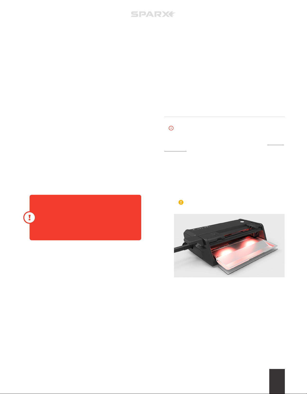
1 REMOVE AND EMPTY THE DUST TRAY
Open the Glass Door and remove the Dust Tray. To empty Dust
Tray—wipe completely clean with a damp cloth (water).
Do not use any solvents or cleaning chemicals in and
around the Skate Sharpener.
2 VACUUM SHARPENER
After removing the Du st Tray, vacuum throughly around the inside of
the sharpener. Detach the vacuum hose from the port on the side of
the machine and use the supplied attachments for this purpose.
3 REPLACE THE DUST TRAY
Slide the Dus t Tr ay back into the machine. Close the
Glass Door.
MAINTENANCE 25
Page 30
TRAVELING WITH THE
SHARPENER
To watch the How-To video, visit sparxhockey.com/travel.
1 REMOVE AND EMPTY THE DUST TRAY
Open the Glass Door and remove the D ust Tray. To empty Dust
Tray—wipe completely clean with a damp cloth (water).
Do not use any solvents or cleaning chemicals in and
around the Skate Sharpener.
5 INSTALL THE TRAVEL SCREW
Install the Travel Screw (A) into the Screw Slot (B) by turning
clockwise until hand-tight.
A
B
6 REMOVE THE CLAMP LEVER
Slide the Clamp Lever (A) o of the Lever Dock.
A
2 VACUUM SHARPENER
After removing the tray, vacuum throughly around the inside of
the sharpener. Detach the vacuum hose from the port on the side
of the machine and use the supplied attachments for this purpose.
3 REPLACE THE DUST TRAY
Slide the Du st Tray back into the machine. Close
the Glass Door.
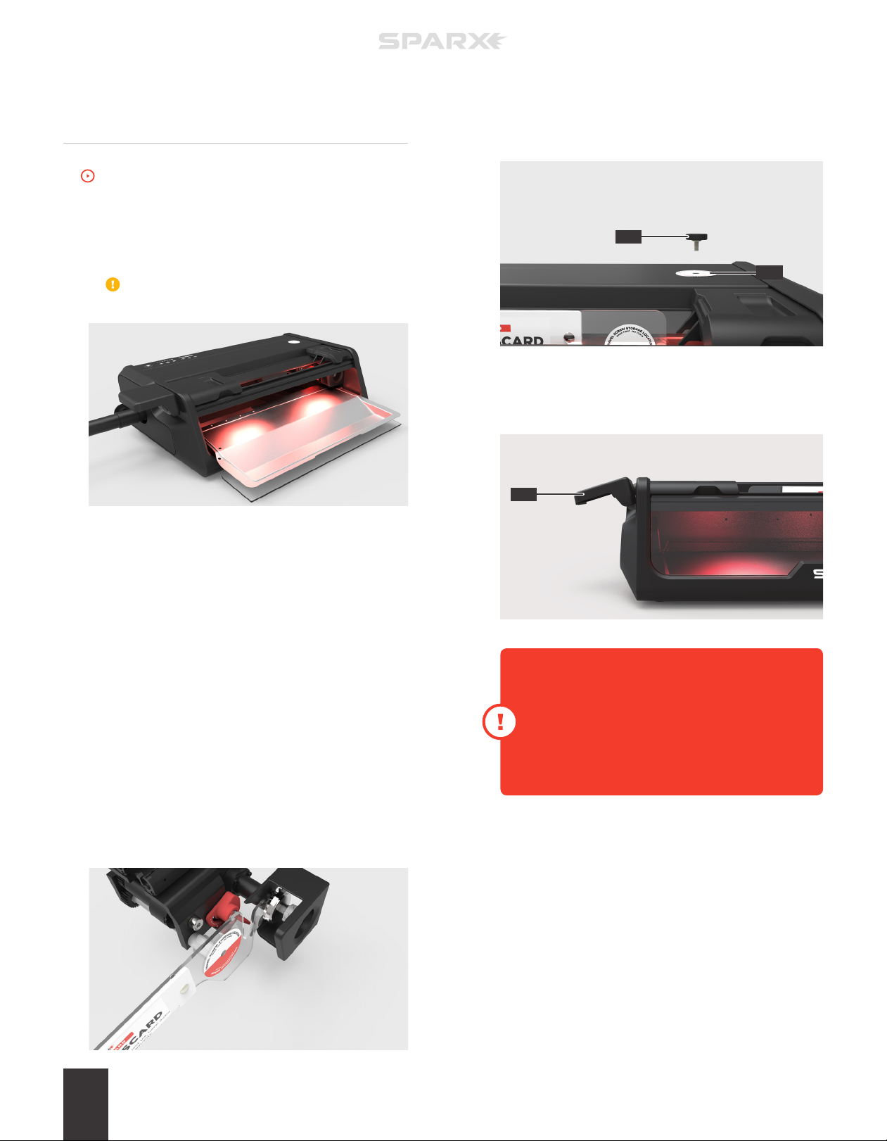
4 INSTALL THE TRAVEL GUARD
Open the Skate Clamp by pressing and holding down the
Clamp Lever. Install the Travel Guard by placing the claw of
the Travel Guard behind the Grinding Ring Shaft’s impeller as
shown below. Release the Clamp Lever. Ensure that the
middle section of the Travel Guard is held securely in
the Skate Clamp.
When setting up the Sparx sharpener after travel,
wipe down the Grinding Ring Shaft’s face and
threaded arbor to remove any unwanted steel
shavings that may have gathered during transit. This
will ensure a proper fit between the Grinding Ring
Shaft and the Grinding Ring.
When setting up the Sparx Sharpener after travel,
wipe down the Grinding Ring Shaft’s face and
threaded arbor to remove any unwanted steel
shavings that may have gathered during transit.
This will ensure a proper fit between the Grinding
MAINTENANCE26
Page 31

WARRANTY
VELASA SPORTS MAY, AT ANY TIME AND IN ITS SOLE
DISCRETION, MODIFY ANY OF THE TERMS AND CONDITIONS
CONTAINED IN THE WARRANTY POLICY. ANY PURCHASE
OF A SPARX HOCKEY PRODUCT IS COVERED UNDER THE
ASSOCIATED PRODUCT WARRANTIES POSTED AT
7
SPARXHOCKEY.COM/WARRANTIES
AT THE TIME OF SALE OF THE SPARX HOCKEY PRODUCT.
WARRANTY 27
Page 32
VELASA SPORTS, INC. 30 SUDBURY RD. ACTON, MA 01720 USA
COPYRIGHT © 2016 VELASA SPORTS INC.
ALL RIGHTS RESERVED
11254 - 07.20.2017
 Loading...