

Spartherm Stovo S plus, Sino L, Stovo M, Stovo L, Stovo L plus Installation And Operating Manual
...
Installation and Operating Manual
Stoves selection

PREFACE - QUALITY PHILOSOPHY
You have decided in favour of a SPARTHERM stove - thank you for your confidence in our company. In a world of abundance and mass production, we
connect our name with the credo: "high technical quality combined with a
contemporary style, as well as service for the sake of the customer's satisfaction and recommendation." We and our trade partners offer you first-class
products that are emotionally moving and also engender feelings of comfort
and security. To ensure this, we encourage you to read the operating manual
carefully so that you can become familiar with your stove and its accessories
quickly and thoroughly. In addition to information on use, these instructions
also include important details on care and operation to guarantee your safety
and to protect the value of your stove as well as useful tips and guidance.
Moreover, we show you how you can operate your stove in an environmentally responsible manner. For further enquiries, please contact your specialist
dealer.
We hope you enjoy your new stove.
The SPARTHERM team
G.M. Rokossa

GB 3
OVERVIEW OF INSTALLATION AND OPERATING MANUAL // STOVE SELECTION
1. General instructions 4
1.1 Certified quality 4
1.1.1 Scope of deliver y 4
1.1.2 Damage while in transport 4
2. Installation instructions 5
2.1 Basic installation requirements 5
2.1.1 Installation site 5
2.1.2 Multiple configuration 6
2.2. Transport and alignment aid 6
2.3. Installation/assembly 6
2.3.1 Changing the flue gas connection direction 8
2.3.2 Combustion air supply 9
2.3.2.1 Room-air-dependent 9
2.3.2.2 Separate combustion air supply 10
2.3.2.3 Room-air-independent 13
2.3.3 Fire safety 14
2.3.4 Shut-off device 18
2.3.5 Connecting piece 18
2.3.6 Installing the heat storage stones on top 18
2.3.7 Installation of the water-bearing
components of the SENSO M H
2
O / PIKO H2O 20
2.3.7.1 Connections of SENSO M H
2
O / PIKO H2O 20
2.3.7.2 Basic requirements for installation
20
2.3.7.3 Thermal discharge safety device ( TAS) 21
2.3.7.4 Thermal pump controller 22
2.3.7.5 Electrical connection 22
2.3.7.6 Integration and heating system 23
2.3.7.7 Return flow temperature boost 25
3. Operating Manual 25
3.1. General information on operation 25
3.2 S-Thermatik Mini 26
3.2.1 Commissioning the S-Thermatik Mini 26
3.2.2 Functional check of S-Thermatik Mini 27
3.3 Function of the rotary-base 28
3.4 Type plate 29
3.5 Operation of the water heat exchanger
Senso H2O / PIKO H2O 29
4. Combustion 29
4.1 Initial commissioning 29
4.1.1 Combustion air regulation 30
4.2 Heating-up / firing 31
4.2.1 Adding wood 31
4.2.2 Hourly wood feed quantity 32
4.3 Controlling heat output 32
4.4 Room heating capacity 32
4.5 Heating in the shoulder seasons/during unfavourable weather conditions 33
4.6 Chimney fire 33
5. Fuel 33
5.1 C O
2
Neutrality 33
5.1.1 Wood storage 34
5.2 Your contribution to environmental protection 34
6. Cleaning and care 34
6.1 Cleaning the combustio chamber/cladding parts 34
6.2 Firebox lining 36
6.3 Maintenance 39
6.3.1 Lubrication manual for door latches with
Smartclose 39
6.3.2 Maintenance of the water heat exchanger SENSO M
H
2
O / PIKO H2O
40
6.3.3 Venting the water heat exchanger SENSO M H2O /
PIKO H
2
O
40
6.4
Cleaning the water heat exchanger
SENSO M H2O / PIKO H2O
40
6.5 Türmechanik SENSO S RLU 41
7. Troubleshooting 43
7.1 W
ater heat exchanger SENSO M H2O / PIKO H2O 45
8. General warranty conditions 45
8.1 Area of application 45
8.2 General information 46
8.3 Warranty period 46
8.4 Warranty requirements 46
8.5 Exclusions from the warranty 46
8.6 Elimination of defects / repair 47
8.7 Extension to the warranty period 47
8.8 Spare par ts 47
8.9 Liability 47
8.10 Closing remarks 47
9. Technical data 47
10. Commissioning protocol 52

GB 4
1.1 CERTIFIED QUALITY
OUR STOVES ARE TESTED IN ACCORDANCE WITH DIN EN 13240. DECLARATION OF PERFORMANCE IS AVAILABLE AND CAN BE VIEWED AT WWW.
SPARTHERM.COM
These stoves are equipped with a self-closing fire door which means the
door is only opened when the fireplace has to be serviced (e.g. to clean
the combustion chamber or add more fuel). For safety reasons, the closing
mechanism must not be tampered with; furthermore, any such action would
render the warranty and operating licence null and void. The guarantee and
operating licence are also rendered invalid if the customer modified the
technology of any other area of the stove.
1.1.1 SCOPE OF DELIVERY
• Fireplace made of Vermiculite / Schamotte
• Primary and secondary air supply
• Pull-out ash pan or ash box and grate (not all models)
• Self-closing fire door with high-temperature-resistant ceramic glass.
• Insulated glove*
• Rating plate („3.4 Type plate“ on page 29)
• Supplied pre-assembled in transport-friendly disposable cardboard
packaging
• Heat storage stones (only on CUBO M, PIKO M, SENSO L (optional), PASSO
M, STOVO M)
• Pump thermostat, thermal discharge safety device ¾", bleeder (only on
SENSO M H
2
O, PIKO H2O)
• Integrated cleaning system with control lever (only on PIKO H
2
O)
1.1.2 DAMAGE WHILE IN TRANSPORT
Immediately on arrival, please check the goods delivered (visual inspection). Note down any possible damage on your delivery note and then please
1. GENERAL INSTRUCTIONS
Please consult your district master chimney sweep before assembling and
installing the stove. He will advise you of building law regulations, the
suitability of your chimney, and will conduct the acceptance procedure for
your stove. The chimney calculation is executed in accordance with DIN EN
13384 with the value triplet specified in this manual („9. Technical data“
on page 46).
Important for small children, elderly or infirm persons: As is the case with
all other heating devices, it is expedient that you attach a protective fixture
for these groups of persons, as the view pane and the cladding parts of the
stove can become extremely hot!
Danger of burn injuries!
Never touch the stove when the fire is burning or has just been extinguished! The stove should never be operated for an extended period of time
unattended.
The enclosed heat protection glove is exclusively designed to activate the operating handle and the “cold hand”. The glove is not
fire-proof!
National and European standards, the respective state-specific and local
directives and regulations, and the respective firing installation ordinance
of the German Federal State, must be complied with for setup and operation
of your stove and for the connection to the chimney.
The stove must always be operated with the door closed. Modification of the
closing device is prohibited!
* Important: The glove provided serves only as thermal protection and is not
fireproof.

GB
GB 5
inform your stove fitter. Protect the visible elements of the stove from soiling and damage during installation. Only permitted and sufficiently strong
transport aids may be used to transport the stove.
The following points must be noted to ensure safe and problem-free
transport:
• It should be shipped in an upright position or slightly tilted on its back!
• Sack trucks used as a transport aid may only carry the stove from the
back.
2. ASSEMBLY INSTRUCTIONS
The assembly and installation of your stove must be carried out by a specialist. Please consult your district master chimney sweep before assembling and installing the stove to clarify the suitability of the chimney system
and the installation site, and also when having any further questions.
2.1 BASIC INSTALLATION REQUIREMENTS
For installation, connection and operation of the stove, all relevant national
and European standards, as well as local regulations (DIN, DIN EN, state
construction ordinances, firing ordinances, etc.) must be complied with and
applied! The list of regulations given below is not exhaustive.
In the UK all stoves must be fitted in accordance with UK local building and
HETAS regulations. Appliances may only be commissioned by HETAS accredited installers. Only appliances registered with DEFRA may be installed in UK
smoke controlled area.
FeuVo: Feuerungsverordnung (Firing Installation Ordinance) of the respec-
tive German Federal State
LBO: Regional building regulations and fire regulations of
VKF: VKF (Switzerland)
LRV: (Switzerland)
1. BlmschV: Erste Verordnung zur Durchführung des Bundes-Immis-
sionsschutzgesetz (First Ordinance on the Implementation of the Federal
Emissions Control Act)
TROL: Technical Rules of Tiled Stoves and
Hot Air Heating System Trade (ZVSHK)
DIN 1298 / EN 1856: Connecting flue pipes for heat generating systems
DIN EN 13240: Roomheaters fired by solid fuel
DIN 18896: Fireplaces fired by solid fuel Technical rules:
for installation and operation
DIN EN 13384 Chimneys: Thermal and fluid dynamic calculation methods
DIN 18160-1/2: Chimneys/house chimneys
DIN 4751 / DIN EN 12828: Heating systems in buildings –
Design for water-based heating systems
VDI 2035: Water treatment for heating systems
Art. 15a: B-VG (Austria)
Fireplaces may only be installed in rooms and places where the location,
construction situation and type of utilisation do not lead to hazards. The
floor area of the installation must be of a design and size so that the fireplace can be operated properly and as intended.
2.1.1 INSTALLATION SITE
Your stove must not be installed:
1. In stairways, unless they are in residential buildings with two or fewer
flats.
2. In hallways with general access.
3. In garages.
4. In Fireplace systems in rooms or flats that are ventilated through ventilation systems or warm air heating through the use of fans, unless the
safe operation of the stove is ensured.
5. In rooms in which highly combustible or potentially explosive substances
or mixtures are processed, stored or manufactured in quantities that

GB 6
Attention! The transport and alignment aids may only be used on a stable
subfloor. Soft, delicate floors can be damaged by the high surface pressure
of the transport casters!
2.3 INSTALLATION/ASSEMBLY
Your stove must be installed on floors with sufficient load-bearing capacity.
Please observe the overall weight („9. Technical data“ on page 46)! The
load-bearing capacity may have to be ensured by a sufficiently thick board
(weight distribution).
Observe the necessary measures for fire protection in the floor area when
choosing the installation location. („2.3.3 Fire safety“ on page 14)
Stability "9. Technical data“ on page 6
Stoves with an upright design and fitted heat storage stones must be
secured against unintentional tilting because of their top-heaviness.
The stove is placed on the floor in compliance with the safety distances
(„2.3.3 Fire safety“ on page 14) and aligned horizontally. The feet are
adjustable in height.
Flue pipe elbow kit
Install the stove with the flue pipe bend set that we offer and refer to the
following for the stove-specific connection height dimensions.
Flue pipe elbow kit, colour version
Order no.
Unpainted Black Graphite Ter ra Pearl
- 1017770 1017 76 9 1017772 1017771
would be hazardous in the event of ignition or explosion
Room air independent stoves can be placed in rooms, apartments or utilization units of comparable size from which air can be sucked out using
fans such as ventilation or hot air heating systems. The condition is that the
vacuum-capable equipment cannot create a vacuum > 8 PA.
2.1.2 MULTIPLE CONFIGURATION
Multiple use of the chimney in accordance with DIN 18160 is possible
because the stove has a self-closing fire door (A1). All fireplaces connected
to a chimney must also be approved for multiple use!
The following applies to room-air-independent stoves:
A multiple chimney configuration is prohibited!
2.2 TRANSPORT AND ALIGNMENT AID
The Spartherm stoves Moro and Noto with integrated transport and alignment aid give you the possibility to move the stove to the installation location with little effort and be able to perform the alignment quickly.
To do this, it is necessary to fully screw in the adjustable feet set into the
lower wood compartment to align the stove.
After screwing in the feet, the entire weight load of the stove is supported
by the transport casters set into the base. Now it is possible to move the
stove back and forth.
Please ensure that the fitted natural stone elements do not move or fall off
the stove! After positioning, unscrew the adjusting feet and ensure the stove
is standing securely.
Moro
Noto

GB
GB 7
Fig. 1a
Fig. 1b
Stove
Bore
Ø 150 mm
A
in mmB in mm
Stovo
Stovo S 990 1682
Stovo S plus 990 1682
Stovo M 990 1682
Stovo L 990 1682
Stovo L plus 990 1682
Sino
Sino L 1091 1837
Sino City 1091 1837
Moro 1070 1844
Noto 924 1665
Senso
Senso S 916 1639
Senso S RLU 916 1639
Senso M H2O 1157 1906
Senso L 1138 1882
Senso L 2015 1172 1916
Passo
Passo XS 958 1719
Passo XS RLU 958 1719
Passo S 1147 2015
Passo M 1248 2215
Passo L 1383 2115
Passo S 2015 1282 1880
Passo M 2015 1247 2215
Passo L 2015 1382 1980
Piko
Piko S 973 1712
Piko M / L 1113 1852
Piko M / L with log storage compartment
1113 1852
Piko S RLU 973 1739
Piko M RLU 1113 1852
Piko M RLU with log storage compartment
** **
Piko L RLU 1253 2019
Piko L RLU with log storage compartment
** **
Cubo
Cubo S 973 1712
Cubo M / L 1113 1852
Cubo M / L with log storage compartment
1113 1852
Cubo S 973 1739
Cubo M RLU 1113 1852
Cubo M RLU with log storage compartment
** **
Cubo L RLU 1253 2019
Cubo L RLU with log storage compartment
** **
Redoro
Redoro S 1253 1992
Redoro M 1253 1992
** Data are not yet available
Dimension A: Flue pipe connection height with dis-
charge to the back
Dimension B: Flue pipe connection height with use of
the flue pipe bend set

GB 8
Make sure that the sealing elements are correctly positioned under the
dummy cover and the flue gas outlet and ensure a tight seal. After screwing
in tight, fit the optional storage elements and convected air gate to prevent
airflow in reverse order and fit the lining elements (Fig. 8).
Note: The installation steps may be different depending on each stove model.
Special notes on the Piko H20 model
The Piko H
2
0 model has gas evacuation to the side and to the top in addition
to the option of connecting the connecting piping around a corner. If the
installation situation of the Piko H
2
O stove has been decided already during
the planning phase, it is possible to order the stove with preassembled
matching flue gas outlet from the factory.
If the orientation of the flue gas outlet on site has to be changed, please
proceed as follows:
Installation from the top to the back/side
The flue gas outlet can be connected to the back in three different positions:
Carefully remove the top plate (A) (Fig. 9) of the stove and place it in a
protected place. When removing the top plate, ensure that the fitted dummy
cover (B) (Fig. 10) does not fall and get damaged.
A
B
C
D
A
B
C
D
E
C
E
C
D
E
C
D
C
D
C
D
C
D
D
Fig. 1
Fig. 5
Fig. 2
Fig. 6
Fig. 3
Fig. 7
Fig. 4
Fig. 8
2.3.1 CHANGING THE FLUE GAS CONNECTION
DIRECTION
The stove is prepared for the flue gas connection at the top when delivered.
Depending on the model, the flue gas connection position can be changed
so that it is aligned to the back, to the side or around corners. Follow these
installation steps when changing the flue gas connection position:
Changing the flue gas connection direction from to the top to the
back using the example of the Senso S
Installation from the top to the back
Remove the top plate (A) (Fig. 1) of the stove carefully and place it in a
protected place. When removing the top plate, ensure that the fitted dummy
cover (B) (Fig. 1) does not fall and gets damaged. Depending on the model,
the top plate of the stove must be removed either upwards in advance or
unlocked by parallel displacement to the front (model Stovo).
In stoves with fitted heat storage stones (for example, Cubo / Piko M (Fig.
2)) or convected air regulation (Fig. 3), these components must be removed
(„2.3.6 Installing the heat storage stones on top“ on page 18).
After removing the top plate, the flue gas connection piece (C) (Fig. 4)
bolted onto the stove body is visible. Remove these by loosening the internal
hexagonal bolts (SW 13). Now remove the dummy cover (D) (Fig. 5) on the
back of the covering panel for feed-through of the flue gas pipe. Depending
on the model, the perforation for this must be broken through or 2 fixing
screws loosened.
The only visible dummy cover (E) (Fig. 6) must be unscrewed using the
internal screws (SW13) and replaced with the previously removed flue gas
outlet (C) (Fig. 4). Fit the removed dummy cover (PE) onto the upper flue gas
outlet in order to close this (Fig. 7) (screw connection SW13).

GB
GB 9
After removing the top plate, the flue gas connection piece (C) (Fig. 10)
bolted onto the stove body is visible. Remove it by loosening the internal
hexagonal bolts (SW 13). Then, remove the back cover plate (Fig. 10) using
the screw connection. A blanking plug for the flue gas outlet to the back/
side is visible (E) (Fig. 11) behind the cover plate. Unscrew this.
Now fit the flue gas connection pipe depending on the desired orientation to
the right/left side or straight back. For the right/left side connection type, a
separate connecting piece is supplied with the Piko H20 stove (Fig. 13). The
top connecting piece is used for the back connection type. Ensure that the
underlying caulking strip is placed correctly and seals tightly.
The removed dummy cover (E) is screwed in place as shown in (Fig. 12) and
seals the flue gas outlet at the top.
Finally, close the open cladding openings at the back of the stove with the
enclosed cover plates and fit the top plate (Fig. 14).
2.3.2 COMBUSTION AIR SUPPLY
The combustion air can be supplied in accordance with „2.3.2.1
Room-air-dependent“ and „2.3.2.3 Room-air-independent“ in different
ways
.
2.3.2.1 ROOM-AIR-DEPENDENT
Your stove draws the combustion air from the installation area (room air dependent operation). Ensure that the installation area is adequately supplied with
fresh air (more details in the country-specific FeuVO, DIN 18896, the technical
regulations, etc.). The fresh air supply must be checked by the installer and the
operator. When operating several fireplaces in a single room or linked space,
ensure that sufficient air is available for complete combustion! It is possible that
there is not a sufficient supply of fresh air if the windows and doors are sealed
(e.g., in combination with energy saving measures). As a result, the ventilation
of the tiled stove can be affected. This can adversely affect your well-being
and, potentially, your safety. If necessary, an air valve must be installed near
the pellet stove for the additional supply of fresh air, or a combustion air line
must be routed outwards („2.3.2.2 Separate combustion air supply“) or in a
well-ventilated room (except for the heating room). In particular, ensure that the
Outlet on the left side
Outlet to the centre
Outlet on the right side
A
B
C
D
E
Fig. 9
C
D
E
Fig. 10
E
Fig. 11
Fig. 12
A
B
C
D
E
Fig. 13
Fig. 14

GB 10
necessary combustion air pipes are open during the operation of the fireplace
insert. Simultaneous operation with a ventilation system (e.g. extractor hood,
bathroom fan, etc.) in the same room or connected space can adversely affect
the function of the stove (to the point of smoke or flue gas accumulating in the
living room, despite the firebox door being closed). It is therefore prohibited
to operate appliances of this kind simultaneously with a fireplace without first
taking appropriate precautionary measures („2.3.2.3 Room-air-independent“).
2.3.2.2 SEPARATE COMBUSTION AIR SUPPLY
The stove can be supplied with combustion air separately. The separate combustion air connection can be connected to the rear side or from below. The
connecting piece is preassembled and the cladding must be opened accordingly. When connecting a pipe connection to the combustion air neck, the
combustion air can be supplied to the stove from the outside or from other
rooms such as the cellar. When connecting the stove to a combustion air line,
the TROL instructions (technical rules), the DIN 18896, etc. must be observed
and applied.
In particular, ensure that the dimensions of the pipes are adequate!
When using the rotary base, the connection must be designed as
durable and flexible! The ability for it to rotate must not be affected.
The combustion air openings and lines must not be closed or blocked other than
if it has been ensured that the fireplace can only be operated with opened fastening by special safety equipment. The cross-section must not be narrowed by a
fastening or a grille. This measure is not necessary with LAS chimneys. A shut-off
valve must be installed, where the combustion air feed line runs outside the building. In doing so, it must be possible to easily determine the shut-off valve setting
from outside of the connecting line. In this version, the pipe should be insulated
to prevent condensation. The pipe should be positioned, so that any condensation
formed can run out of the pipe and any water or other foreign substances from
outside cannot get into the stove. In accordance with regulations, combustion
air piping crossing a fire wall in buildings with more than two storeys must be
established in such a manner that smoke or fire cannot be transmitted to other
floors or fire compartments. Country-specific and local fire safety regulations
must be observed!
SPARTHERM QUICK COUPLING - SQC COUPLING
Compatible with the following stoves:
• Senso S
• Piko / Cubo S/M/L
• Passo XS
• Passo S/M/L
• Redoro S/M
The installation location of the stove must be determined according to the
specified technical data for the supply channel / hole. For direct wall mounting, the combustion air and flue gas connection must be prepared on one
level. The stove is delivered with the fitted SQC coupling and the adjustable
feet extended. In this condition, the connecting piece is in the air, and there
is no contact to base unit. Therefore, the stove can be transported as usual
with the normal tools (e.g. sack truck).

GB
GB 11
Assembly sequence
1. Position the stove with the extended adjustable feet in its final
position.
2. Screw in the adjustable feet to adjust the stove to its nominal height.
When lowering it, the SQC connecting piece makes contact with the
base unit and encloses the supply opening on the site side.
Transport position with SQL coupling
Fig. 15
Example of Senso S:

GB 12
Companion dimensions of a stove with SQL coupling
For dimension A and dimension B, see point „2.3 Installation/assembly“
on page 6.
Dimension C:
Distance from the mounting wall to the centre air supply hole. Ensure the
clearances of the flue pipe connection to the chimney are complied with!
Stove
Date of
construc-
tion
Order no.
C in mm
Bore Ø 100 mm
for a combu stible mounting
wall
for a mount ing
wall that is n ot
to be protected
Senso S
from
11/2014
1033724 308 258
Passo XS
1033726 286 286
Passo S
from
07/ 2015
1033727 340 290
Passo M
1034352 340 290
Passo L
1035352 340 290
Cubo S
from
11/2014
1033728 303 252
Piko S
1033728 302 252
Cubo M
1033726 309 259
Piko M
1033726 309 259
Cubo L
1033726 309 259
Piko L
1033726 309 259
Redoro S
1037704 302 252
Redoro M
1037704 302 252
Fig. 16
B
A
C

GB
GB 13
Note on Redoro S and M
The separate combustion air connection can be connected from below and
comes out to the back or to the side. The connecting piece is preassembled
and the cladding must be removed accordingly.
1. Open the stove door and remove the four countersunk screws at the
bottom.
2. Remove the lower cover part by grabbing it at the side and pulling it
towards to the front.
3. Connect the connecting pipe shown here in blue with the receiving
unit for the SVS connecting piece.
4. After connecting the combustion air connection, push the lower cover
part onto the receiving unit as shown in green here and fix it with the
four countersunk screws.
2.3.2.3 ROOM-AIR-INDEPENDENT
The RLU stoves have been developed for use with residential ventilation systems
for a vacuum range of up to 8 Pa in the installation area and can be operated
without additional safety equipment. The combustion air must be supplied in
airtight lines from the outside or via an LAS system to the device for room-air-independent operation without fail. To do this, the combustion air duct must be
permanently sealed to the combustion air neck (connection type back/side or
bottom) of the stove.
When connecting the RLU stove to a combustion air line, the TROL instructions (technical rules), the DIN 18896, etc. must be observed and applied.
In particular, ensure that the dimensions are adequate!
Country-specific and local fire safety regulations must be observed! Make
sure that the pipes are always airtight.

GB 14
2.3.3 FIRE SAFETY
The handover inspection of your stove before commissioning is performed
by the chimney sweep responsible. You can also advise the chimney sweep
prior to installation about installation conditions on site, and can provide
advice on how to install your stove properly.
General Information on fire prevention
Stoves are heat generators and are subject to regulations and necessary
measures for fire protection. The fire regulations and the recommended
minimum clearances of the device must be observed even when selecting
the installation site. Basically, a minimum wall clearance of 5 cm to
the back wall must be adhered to. For reasons of safety and fire
protection, larger clearances must be ensured to protected walls or
combustible materials.
In the following table on page 17, the permissible clearances are documented according to the type of the stove and the type of on-site mounting
wall. Using the diagrams (Fig. 19-23), match the mounting situation, taking
into account the specified distances that need to be complied with.
Follow the instructions for fire protection during installation and
ask your local chimney sweeper.
• Mounting walls that are non-combustible or not to be protected are
suitable to withstand permanent exposure to temperatures > 85°C thanks
to their structure and their material type.
• Mounting walls that are combustible or to be protected (e.g. timber frame
construction) must be protected from temperatures > 85°C.
Before installing the stove, it is necessary to evaluate the mounting walls. If
the type of mounting wall cannot be clearly assigned, a specialist (chimney
sweep) must be consulted.
• Wallpaper as wall coverings in accordance with DIN 4102-1 are
non-combustible components and do not require special precautions
for fire protection. Ensure here that the underlying structure of the wallpaper (e.g. timber frame construction) is very easily ignited or must be
protected and appropriate precautions must be taken!
• Ensure that the specified minimum clearances to the back and side wall
must be adjusted for the rotary devices.
• Ensure that the minimum clearances from chimney connecting piece to
combustible components are adhered to (see „2.3.5 Connecting piece“
on page 18).
• Combustible objects must not be located at a distance of 50 cm above
the fireplace!
Floor coverings near the stove
Floors in front of the combustion chamber opening have to be protected
from combustible materials by a board made of non-combustible materials.
The board must extend over at least 50 cm to the front and at least 30 cm
to the side (Fig. 19-23 C + D) (measured from the combustion chamber
opening or viewing window)!
No combustible components, furniture, curtains or decorations may be
placed in the area of direct radiant heat of the fire door or inspection glass.
This distance may be reduced to 400 mm if radiation protection plates are
installed between the fireplace and combustible structures on both sides.

GB
GB 15
Minimum distances to adjacent components
Depending on the view pane arrangement (see the following graphics) of
your stove and the type of mounting walls, the distances from the table are
to be adhered to.
The following describes
• Distance A as the minimum distance of the stove sidewall to the mounting wall
• Distance B as the minimum distance of stove back wall to the mounting
wall
• Distance C as the area of direct radiant heat in front of the view pane
(n) of the stove
Special note on minimum side distance
Minimum side distance (Fig. 17 (A)) describes the minimum distance from
the stove to the side mounting wall and is valid from the back mounting wall
to the beginning of the area of direct radiant heat (E) of the front panel.
In stoves with curved front pane or a wide area of direct radiant heat, the
minimum wall distance (A) must be adjusted to the extending area of direct
radiant heat.
Determining the area of radiant heat
To layout the area of direct radiant heat of the stove, put a measuring
instrument (ruler or measuring tape) on the surface of the view pane and
determine the centre of the fireplace past the side door pillar (Fig. 18). In
the resulting angle and the distance A1, there must be no combustible or
components to be protected on the sides.
brennbar
(z.B.Sessel)
A1
C
Meterstab
Bodenbelag
D
Strahlungsbereich
Fig. 18
brennbar
(z.B.Sessel)
E
A
Strahlungsbereich
Bodenbelag
D
Fig. 17
Radiant area
Flooring
Combustible
e.g.
(armchair)
Radiant area
Flooring
Combustible
e.g.
(armchair)
Folding rule

GB 16
Fig. 21
Bodenbelag
brennbar
(z.B.Sessel)
Strahlungsbereich
C
B
A
D
Wide area of direct radiant heat
Bodenbelag
Strahlungsbereich
Strahlungs-
bereich
A
B
C
D
brennbar
(z.B.Sessel)
Fig. 22Front and side pane
Fig. 23
C
Strahlungsbereich
A
Bodenbelag
C
D
brennbar
(z.B.Sessel)
Front pane, rotatable
Bodenbelag
C
Strahlungsbereich
A
D
B
brennbar
(z.B.Sessel)
Fig. 19Front pane, flat
Strahlungsbereich
A
B
C
Bodenbelag
D
brennbar
(z.B.Sessel)
Fig. 20
Corner pane
Radiant area
Flooring
Combustible
e.g.
(armchair)
Radiant area
Combustible
e.g.
(armchair)
Flooring
Radiant area
Flooring
Combustible
e.g.
(armchair)
Radiant area
Flooring
Combustible
e.g.
(armchair)
Radiant area
Radiant area
Flooring
Combustible
e.g.
(armchair)

GB
GB 17
* The distance is only valid in conjunction with a radiation protection plate on the top plate, which is fitted behind the vertical flue gas pipe.
Stoves Distance to side wall Distance to theback wall Distance in the area of direct radiant heat of
the pane(s).
Dimensions of the fire protection floor
covering
A (cm) B (cm) C (cm) D (cm)
combustible No protection
required
combustible No protection
required
combustible No protection required Length x width Radius (with round floor
covering)
Piko S / Piko S RLU 10 10 10 5 80 80 50 x 30 50
Piko M / Piko M RLU 10 10 10 5 80 80 50 x 30 50
Piko L / Piko L RLU 10 10 10 5 80 80 50 x 30 50
Piko H
2
O 10 10 10 5 80 80 50 x 30 50
Cubo S / Cubo S RLU 10 10 10 5 80 80 50 x 30 50
Cubo M / Cubo M RLU 10 10 10 5 80 80 50 x 30 50
Cubo L / Cubo L RLU 10 10 10 5 80 80 50 x 30 50
Redoro S / M 10 10 10 5 80 80 50 x 30 50
Stovo S 31 20 16 5 80 80 50 x 30 50
Stovo S plus 31 20 16 5 80 80 50 x 30 50
Stovo M 31 20 16 5 80 80 50 x 30 50
Stovo L 56 25 13 5 80 80 50 x 30 50
Stovo L plus 64 25 13 5 80 80 50 x 30 50
Senso S / Senso S RLU 47 20 10 * 5 80 80 50 x 30 50
Senso M H
2
O 10 10 10 5 80 80 50 x 30 50
Senso L / Senso L RLU 45 10 15 5 80 80 50 x 30 50
Sino L 10 10 8 5 80 80 50 x 30 50
Sino City / Sino City RLU 36 10 7 5 80 80 50 x 30 50
Moro / Moro RLU 35 20 20 5 80 80 50 x 30 50
Noto 15 15 20 5 80 80 50 x 30 50
Passo XS / Passo XS RLU 15 15 5 5 80 80 50 x 30 50
Passo S / Passo S RLU 5 5 10 5 80 80 50 x 30 50
Passo M / Passo M RLU 5 5 10 5 80 80 50 x 30 50
Passo L / Passo L RLU 5 5 10 5 80 80 50 x 30 50

GB 18
2.3.4 CUT-OFF DEVICE
Exhaust systems must be created in accordance with the Technical Rules
of Tiled Stoves and Hot Air Heating System Trade (TROL). Stoves should
have a shut-off device in the exhaust gas flue. These devices must not be
self-closing and must not be positioned such as to prevent or hinder the
inspection and cleaning of connecting pipework. The position of the shut-off
device must be visible from the outside, e.g., from the position of the operating handle. Shut-off devices may only be installed in the exhaust manifold
or collecting pipe, the flue gas pipe stub or the pipeline connecting piece.
2.3.5 CONNECTING PIECE
Your stove is connected to the chimney with Ø 150 mm/Ø 160 mm connecting
pieces made of steel plate which is at least 2 mm thick. These connect
ing pieces must satisfy the requirements specified in DIN 1298 and DIN EN
1856-2, and must be connected to the chimney system in accordance with
the requirements specified in DIN 18160 or the country-specific regulations.
It must be ensured that the flue gas pipe is installed in the shortest pos
sible route upwards towards the chimney. To achieve this, ensure that the
flow of flue gas is redirected as few times as possible. Ensure that the flue
pipe is stable; where appropriate, the flue pipe may need to be secured with
brackets. If the flue leads through a combustible wall or is located close to
any combustible components, the flue is to be insulated according to the
respective regulations. The connecting line must always be mounted in such
a manner that it is possible to clean the connecting line at any time.This must
be ensured through a sufficient number of cleaning openings. If the stove is
rotatably mounted, the connecting pipe must be installed so that no negative
effects occur on the fixing. The flue pipe must not also turn. The minimum dis
tance from the chimney connecting piece to any combustible components can
increase the distance from the stove to combustible components, in accord
ance with the manufacturer specifications for the flue pipe. The specified
minimum distances to combustible components as stated in these instructions
refer to the fireplace and must be adjusted if necessary („2.3.3 Fire safety“
on page 14).
Ensure that a cleaning opening is located above the flue pipe connection with
gas evacuation to the top.
2.3.6 INSTALLING THE HEAT STORAGE STONES ON
TOP
The heat storage stones delivered with your stove are packed separately
due to their heavy weight. After the stove has been assigned its location in
the installation space, you can begin with the installation of separate heat
storage stones.
Insert the heat storage stones from the outside to the inside. When the stove
is connected with flue gas connection at the back, the heat storage stone
must be placed in the centre. If you connect the stove at the top, the central
heat stone is not required.
To insert the heat storage stones, remove the cover and the plate to control
the supply of heat. Then insert the heat storage stones as shown.
A = remove
B = insert
C = fit
Passo M:

GB
GB 19
Stovo M:
A = Remove (pull top plate for-
ward and remove upwards)
B = insert
C = insert
D = fit
Senso L*/Senso L RLU*:
* Heat storage stones optional
A = open
B = insert
C = close
Redoro M:
A
B
C
A = remove
B = insert
C = fit

GB 20
2.3.7
INSTALLATION OF THE WATER-BEARING
COMPONENTS OF THE SENSO M H2O / PIKO H2O
Assembly of the water-bearing components, the necessary safety devices,
temperature sensors and similar components must always be carried out by
a specialised company. The Mellino H
2
O / Piko H2O must be installed with all
water-bearing components accessible and inspectable at all times!
The stove as well as all associated immersion sleeves, connectors, moulded
components and pipes must be have the pressure checked prior to commis
-
sioning and checked for airtightness.
2.3.7.1 CONNECTIONS OF SENSO M H2O / PIKO H2O
The connections on the Senso M H2O are located on the back and can be
guided from the inside downwards using the flexible attachment kit. The Piko
H
2
O has its connections on the bottom which can be routed to the back and
the side with the flexible attachment kit.
The connections have transport caps and brass stops for transport purposes.
This must be removed prior to installation. The connections are clearly labelled
and must not be used other than for the specified purpose! In particular, the
integrated safety device (safety heat exchanger) must not be used to heat
water.
For easy installation of the pipes, etc. when during connection through
the floor, there is an installation template that can be downloaded on our
website www.spartherm.com in dealer login. The installation tem
-
plate is valid only in conjunction with the flex attachment kit.
Alternatively, an installation template in the scale of 1: 1 can be requested in
print format from us. The flex attachment kit can be ordered for easy and quick
connection of pipes in the floor and the internal connections.
A = remove
B = Insert front stones
C = insert inner stone
D = insert cover stone (with
handle)
E = fit
Cubo M / Piko M:
E

GB
GB 21
2.3.7.2 BASIC REQUIREMENTS FOR INSTALLATION OF H2O
The Senso M H2O / Piko H2O must only be mounted in thermostatically protected systems in accordance with DIN 4751 or DIN EN 12828. All lines to the
hea
ting network must always be designed so that they can be detached (e.g.
as threaded fitting).
Before the stove is placed in service, it must be filled and ventilated on the
heating side (heating network) and water side (thermal discharge safety
device, safety heat exchanger). After the filling process, check all hydraulic
connections for leaks.
Operation without a water-side connection results in irreparable dam
-
age and invalidates any warranty claims!
In the direct vicinity of the Senso M H
2
O / Piko H2O, a type-tested safety valve
(identification letter H) with an activation overpressure of max. 3.0 bar
must
be mounted in the flow line. A shut-off possibility must not be integrated in the
system between the safety valve and the Senso M H
2
O / Piko H2O. This could
render the safety device inoperable. Moreover, all necessary safety devices
must be integrated in the entire system in such a manner that safe operation is
ensured. A separate safety valve must also be installed, if such a safety valve
is installed at a different point in the entire system (comply with TRD 721!).
When installing, the instructions in the installation and operating manuals of
the installed heating-related components/additive components must always
be complied with!
2.3.7.3 THERMAL DISCHARGE SAFETY DEVICE (TAS)
Since the heating of the Senso M H
2
O / Piko H2O is not automatic and can be
quickly switched off, according to DIN 4751 – Part 2 and DIN EN 12828, the
stoves are equipped with a thermal discharge safety device. For this, a safety
device (safety heat exchanger) is integrated in the Senso M H
2
O / Piko H2O to
137
232
292
135
218
232
292
500
500
383
218
A = inlet of thermal discharge safety
device ½" IG
B = discharge of thermal discharge safety
device ½" IG
C = return ¾" IG
D = flow ¾" IG
E = bleeder
3
/8"
Connections Piko H2O (view from below)
104
138
170
234
273
295
334
A = return ¾" IG
B = inlet of thermal
discharge safety device ½" IG
C = flow ¾" IG
D = discharge of thermal
discharge safety device
½" IG
Connections Senso M H2O (back view)

GB 22
prevent overheating. This safety device must not be used as a water heater.
The thermal discharge safety device is not preassembled for safety reasons
during transport and installation, but instead enclosed in the combustion
chamber. During installation, it must be fitted to the marked connection.
Then, use the adapter to screw the capillary line to the TAS. This has been
tested and approved for a minimum throughput of 900 kg / h of water.
The following instructions must always be complied with for the installation,
so that the safety device can function:
• At the cold water inlet, a flow pressure of at least 2 bar must be available.
This pressure must be constantly ensured. This is because, operation on
a mains-voltage-dependent domestic water supply is not permitted!
• Minimum water throughput of approx. 900 L/h must be ensured. It must
not be possible to shut off this supply line!
• It must be ensured that cold water (5-20°C) is available at any time.
Domestic water supplies is not included in this.
All safety-relevant components must be integrated in the system in such a
manner that function and leak-tightness can be checked at any time. The
discharge of the thermal discharge safety device must be designed in such a
manner that a check (e.g. via a drain with siphon) can take place at any time.
Before commissioning, the cold water pipe must be purged! This flushes out
dirt, which would otherwise impact closing of the TAS. The manufacturer's
instructions for the TAS must be observed.
2.3.7.4 THERMAL PUMP CONTROLLER
For optimum control of the circulating pump, a thermostat is integrated in the
lower compartment. This ensures that the circulating pump starts only with
adequate water temperature (> 60°C). The boiler control or similar devices
can be used as a controller if a switch-on temperature of the pump between
60°C and 68°C is guaranteed. The maximum contact load of the thermal
pump control at alternating current 250 V AC is approximately 10 (2.5) A.
The factory setting of the thermostat has been set to about 62°C. When
the switch-on and switch-off temperature of the circulation pump of return
riser is reached, or undershot, the required water temperature in the water
heat exchanger of the Senso M H
2
O / Piko H2O is determined. Optionally, if
conditions so require, the temperature can be adjusted by the installation
company. To do this, the housing cover of the pump thermostat, which is
located in the lower compartment of the stove, must be removed. After
removing the cover, the temperature range can be changed by adjusting
the red screw.
Please note: If water temperatures fall below 60°C, there is an increasing
risk of temperature falling below the dew point level! This can result in the
formation of shining soot. Furthermore, this shortens the cleaning interval.
We do not recommend that the switch-on temperature is set below 60°C,
but also not set at more than 68°C.
2.3.7.5 ELECTRICAL CONNECTION
The entire electrical installation of the individual components of the heating
system must only be executed by an authorised specialised company. All
electrical installations are to be carried out as per the VDE regulations (e.g.
VDE 0105, VDE 0116, VDE 0100, etc.) and the technical connection conditions of the local power company.
On the Senso M H
2
O / Piko H2O, only carry out the electrical installation
from thermostats to the pump of the return flow temperature riser („2.3.7.7
Return flow temperature boost“ on page 25) and to domestic power grid
(see figure). The temperature-resistant connection line is about 3.0 m long
and already stuck to the thermostat.
The function of the thermostat switch is to be able to test the hot water (e.g.
from kettle) and the thermometer The cladding must be removed to do this.

GB
GB 23
2.3.7.6 INTEGRATION IN A HEATING SYSTEM
Please note: The Senso M H2O / Piko H2O must only be installed after detailed
planning of the overall heating system in accordance with the relevant rules
of technology and the safety standards. Proper configuration of the pumps,
fittings, pipeline, buffer tank and the safety components is the responsibility
of the planning firm and/or of the company in charge of installation. For
heating lines, we recommend a minimum nominal diameter:
copper pipe of 22 x 1.0 mm, or 3/4" for steel pipe.
With cold water pipes, a pipe diameter (copper pipe) is 15 x 1.0 mm and a
flow pressure of 2.0 bar is sufficient for safe operation.
However, dimensioning of this pipework must be carried out by the specialist
company in charge, taking due account of on-site conditions.
Integration of the Senso M H
2
O / Piko H2O can be carried out based on the
diagram on the next page.
A buffer tank must be connected up. German legislation 1st and 2nd BImSchV
mandates the design of volume for this buffer tank. This regulation specifies
that for each kW water capacity, at least 55 liters of buffer volume must be
kept.
Senso M H
2
O
For the Senso M H
2
O, these are: 5.0 kW x 55 litres / kW = 275 litres.
Piko H
2
O
For the Piko H
2
O, these are: 4.6 kW x 55 litres / kW = 253 litres.
Since these are not normal market sizes, the next larger buffer tank should be
chosen with 300 or 500 litre capacity.
°C
C
2
1
L'
N
PE
PE
N
L
E
F
B
D
C
C
2
1
L'
N
PE
E
F
F
A
B
D
C
A = The yellow-green wire is wired to the protec-
tive conductor (earth) (PE) of the feeder
B = thermostat as a pump control,
with approx. 3.0 m connecting line
2 x 0.75 mm
2
C = return flow temperature boost (circulation
pump)
D = terminal 1 not necessary!
E = phase (L) brown line
F = switched phase (L`) blue line
Blue
yellow/
green
Brown

GB 24
The following sample calculation can be helpful for dimensioning the buffer
tank:
The following assumptions have been made in this regard:
Senso M H
2
O Piko H2O
• Size of the buffer tank: 750 l
(approx. 750 kg water)
• Water temperature in the buffer
tank at the beginning: 30°C
• Water temperature in the buffer
tank at the end: 60°C
• Temperature differential 30°C
(corresponds to 30 K)
• Water is not taken from the tank
during heating by the Senso M
H
2
O!
• Size of the buffer tank: 500 l
(approx. 500 kg water)
• Water temperature in the buffer
tank at the beginning: 40°C
• Water temperature in the buffer
tank at the end: 70°C
• Temperature differential 30°C
(corresponds to 30 K)
• Water is not taken from the tank
during heating by the Piko H
2
O!
Q = cp×m×∆t
Q = 4,187 kJ × 750kg×30K
kg×K
Q = 94207 kJ
Q = cp×m×∆t
Q = 4,187 kJ × 500kg×30K
kg×K
Q = 62805 kJ
This means: To heat up 750 litres
of water in a buffer tank, from an
assumed 30°C to 60°C, a theoretical heat quantity of 94207 kJ is
required (losses or heat withdrawals in the system have not been
taken into account). This heat
quantity corresponds to approx.
26.2 kWh.
This means: To heat up 500 litres
of water in a buffer tank, from an
assumed 40°C to 70°C, a theoretical heat quantity of 62805 kJ is
required (losses or heat withdrawals
in the system have not been taken
into account). This heat quantity
corresponds to approx. 17.5 kWh.
ϑ
E
F
G
H
K
L
M
N
P
O
Q
R
S
I
J
B
T
C
D
A
A = temperature sensor for thermal discharge safety valve
B = temperature sensor for thermostatic switch ½'' IG
C = return ¾'' IG
D = flow ¾'' IG
E = safety valve 3 bar
F = bleeding
G = thermostatic switch - pump
H = return riser
I = connection for heating system
J = buffer reservoir
K = return flow temperature boost
L = circulation pump
M = filling and draining fitting
N = diaphragm expansion tank
O = thermal discharge safety device
P = free discharge in e.g. sewer network
Q = "discharge" safety heat exchanger ½'' IG
R = "inlet" safety heat exchanger ½'' IG
S = bleeding
3
/8¨
T = thermal discharge safety device

GB
GB 25
At an average assumed water power
of approx. 5.0 kW of the Senso M
H
2
O, heat-up of the entire buffer
tank of 750 litres of water takes
approx. 5.25 hours. This calculation
is based on the uniform heating of
the entire tank volume.
At an average assumed water power
of approx. 4.6 kW of the Piko H
2
O,
heat-up of the entire buffer tank of
500 litres of water takes approx. 3.8
hours. This calculation is based on
the uniform heating of the entire
tank volume.
For a sensible design of the heating system, the hot water should be stacked
in buffer tanks. e.g. in a stratified storage tank! As a resullt, after only a
short heating-up period, hot water is available and the heat utilization can
begin shortly after circulation starts in the Senso M H
2
O / H2O Piko. In this
case, only the excess energy will be stored in the buffer tank, not the energy
required for heating.
On extremely cold winter days, it is possible that the Senso M H
2
O / Piko
H
2
O may also be in operation for approximately 12 hours. The amount of
heat produced in the water meter corresponds theoretically to 60 kWh / 55
kWh. This amount of heat would be sufficient to heat about 1700 litres (from
30°C to 60°C) / 1575 litres (from 40°C to 70°C) are sufficient. As a rule, in
such a situation heat is also continuously withdrawn so that overloading of
the buffer tank (> 90°C) should not occur.
2.3.7.7 RETURN FLOW TEMPERATURE BOOST
The Senso M H
2
O / Piko H2O must be operated with a return flow temperature boost. In operation, the flow temperature should be above 65°C and the
return temperature at least 60°C. So that these temperatures are ensured, a
circulation pump must be installed in such a manner that it only starts up if
62°C has been reached. To reduce the risk of undershooting the dew point
temperatures, a controlled return riser must be installed. Here is where the
control variable, this corresponds to the effective return temperature at the
inlet of the water heat exchanger, is recorded and set to the desired value.
We recommend the use of a return riser – riser of the type LTC 200 from
ESBE, which is available as an option, or a comparable return temperature
riser. Using other possible solutions (such as a four-way mixer valve) has not
proven itself in practice and is therefore not recommended.
We can not accept any liability or guarantee for any stoppage (sooting,
deposits, etc.) or corrosion damage on the water heat exchanger or chimney, etc., that is caused by a missing or malfunctioning return riser.
3. OPERATING MANUAL
Read these installation and operating instructions carefully before installing
and starting up your stove. All objects must be removed from the combustion chamber (except for combustion chamber liner). Have your specialized
dealer instruct you in the control and operation of the stove! National and
European standards and local regulations for operating the fireplace must
be observed!
3.1. GENERAL INFORMATION ON OPERATION
• Small children, elderly or infirm persons: As is the case with all heating devices, it is expedient that you attach a protective fixture for these
groups of persons, as the view pane and the cladding parts of the stove
can become extremely hot! Danger of burn injuries! Never leave these
groups of persons unattended near the stove when a fire is burning or has
just been extinguished! Make these individuals aware of these risks.
• No combustible objects may be placed or laid on the free surfaces and
the panels of the stove. Do not place items of clothing on the stove to dry.
Racks for drying clothing may only be placed outside the radiation area!
• The surfaces of your stove components (including the surfaces, the door, the
door and operating handles, glasses, flue pipe) are quickly made hot by heat
energy released during the combustion process. Do not attempt to touch these
components without protection (i.e. heat-resistant gloves).
• The enclosed heat protection glove is exclusively designed to

GB 26
activate the operating handle and the “cold hand”. The glove is
not fire-proof!
• The stove may only be operated with the fire door closed. The door should
be kept in a cold state is always closed. Only open the door for firing,
refueling and cleaning!
• The fireplace must never be modified! In particular, never insert any instal
lation components into the combustion chamber, combustion air passages
or flue gas flue that have not expressly approved by Spartherm. Your
fireplace warranty and operating permit will be rendered invalid by any
fireplace modification that has not been approved.
• You may find that extractor hoods, ventilation equipment, etc. installed in
the same room (or linked space) as your fireplace or stove have a negative
effect on the operation of the Kaminofen (such as the release of smoke
into the room). These devices should not be used at the same time as your
fireplace or stove, without first ensuring that the necessary room heating
system precautions have been taken. („2.3.2.3 Room-air-independent“)
• In particular when operating several fireplaces in a single room or linked
space, ensure that sufficient air is available for complete combustion!
• This is a temporary fire area thus, longer continuous burning is not
achieved by piling up the fire repeatedly. Continuous burning without piling
up the fire in-between cannot be achieved even through withdrawal of
the combustion air and is also not permitted. A longer heating period is
achieved by repeatedly restoking the fire with suitable amounts of fuels.
• Only non-combustible materials must be placed in the lower compartment
of the cladding!
3.2 S-THERMATIK MINI
Supply voltage: 230 V / 24V (via
wall plug transformer)
Power consumption during operation approx. 10 VA
Power consumption in "Stand-by": ca. 6 VA
Safety class: III (safety extra-low voltage)
Degree of protection: IP 50
The S-Thermatik Mini combustion control is pre-set to your stove ex-factory.
Changes to the control parameters must only be carried out by an installer
/ stove fitter or the customer services. Please also follow the accompanying
service instructions!
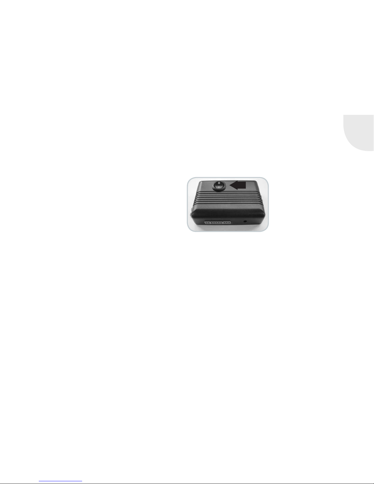
3.2.1 COMMISSIONING THE S-THERMATIK MINI
In order to guarantee an optimum and trouble-free operation of the fire area,
the door contact switch must be kept free from dirt and grime.
Before opening the fire door, make sure that the selector switch points to
"automatic" when the combustion air control is switched on. In automatic
operation, the control is activated from the stand-by by opening the fire
door. Now the actuator motor runs the dosing facility for the combustion
air to the position "open". The logs are placed and ignited (see also "4.
Combustion"), the firebox door closed. Then, the combustion air is set and
controlled automatically via the actuator motor on the basis of the flue gas
temperature measured.
If the flue gas temperature is below 50°C after 10 minutes (after closing the
combustion chamber door), the combustion air is closed again by the control
without further signals. The air control lever moves to the left.
Heat-up errors: flue gas temperature is above 50°C but the pre-set minimum
temperature for starting the control is not reached: If the flue gas tempera
ture then drops below 50°C, the combustion air supply is closed for another
15 minutes. An audible signal sounds. Reasons for a heat-up error could be
that not enough, too much, too large or fuel that is too moist has been added,
or the water heat exchanger pipes are blocked.
If there is a heat-up error and the flue gas temperature continues to increase,
the combustion air supply is throttled depending on the exhaust gas temper
ature. Thus, the primary air (flows over the grate in the combustion chamber)
is closed first and then the secondary air is reduced (differential combus
tion air setting). In doing so, the combustion air lever moves from the right
GB
GB 27
approximately to the middle in steps. In the further course of combustion
and when the flue gas temperature drops, the combustion air quantity is
reduced further.
In doing so, the combustion air lever moves from the middle further to the
left.
Once the flue gas temperature has dropped far enough so that only embers
are in the combustion chamber, you are prompted to add fuel by an audible
tone. If the audible tone is not desired, this can be switched off by means
of the rocker switch. After the signal, you have approx. 10 minutes to add
more fuel without having to use a firelighter. If fuel is added and the fire
door is opened, the control opens the combustion air supply completely to
100% again. In doing so, the air control lever moves back completely to the
right again.
If no fuel is added after the flue gas temperature has dropped even further,
the combustion air is closed to a minimum. After the period of maintaining
the embers, the combustion chamber can be ventilated by opening the combustion air for three minutes. This function allows the ember bed to reduce
further. After the venting process, the combustion air is
closed completely (0%) and the control shifts to standby mode (control
display off).
The correct operation of the S-Thermatik Mini combustion control is indicated by a maintenance-free signal lamp that is mounted behind the fire
symbol in the bottom area of the stove and indicates the movement of the
air control lever.
If the air control lever does not move after opening the fire door, then S-Thermatik Mini mode must be carried out manually using a mechanical release
(changeover of the selector switch) to"manual" mode. The selector switch is
located on the supply air box and is visible when the lower front cladding of
the stove is opened. The combustion air can be adjusted by hand via the air
control lever. For more information about manual adjustment, refer to "4.1.1
Combustion air regulation".
The fireplace insert must never be put into operation with the
combustion air supply (combustion air lever all the way to the left)
closed!
Heat-up errors and the prompt for adding fuel are indicated by an audible
signal. The acoustic signal can be switched off using the rocker switched
mounted on the control housing.
3.2.2 FUNCTIONAL CHECK OF S-THERMATIK MINI
When commissioning the control each time (inserting the wall plug transformer into the socket or when shifting the selector switch from manual to
automatic), this carries out a self test when the fire door is closed. In doing
so, the air control lever moves from the left to the right and after a rest
period of max. 1 minute, back to the left again. The air control lever only
moves to the left if the door contact and the flue gas temperature sensor are
functional. The self test should be carried out when the combustion chamber
is cold. When the combustion chamber is hot, the air control lever does not
move completely to the left, it takes the respective position according to the
current flue gas temperature. When the stove is cold and after this self test,
the control shifts to stand-by mode and "waits" until the fire door is opened.
To perform the self-test on your own:
• Move the selector switch to manual
• Insert the wall plug transformer into the socket

GB 28
• Position the air control handle in the middle by hand (about 50%)
• Move the selector switch to automatic
• The LED must light up and the air control lever must move to the right.
If the lever moves to the left first, swap the white and red wires on the
control with each other.
• After a maximum of 1 minute, the air control lever must move to the left.
If not, swap the blue and brown wires on the control with each other and
repeat the self test.
• Open the fire door, the air control lever must move to the right.
• End of the self test. You can now fire-up the stove.
If no fire is started, approx. 10 minutes after closing the door on, the air
control lever moves back to the left to 0%.
3.3 FUNCTION OF THE ROTARY-BASE
Installation of a rotary base can only be executed at the top and must be
stated when ordering. The stove is can rotate through 180°, 90° to the
left and right respectively (Sino L 120 ° rotatable, 60° to the right and left
respectively Fig. 24).
To allow the Senso S stove to rotate, loosen the adjustment bolt/the stop
(Fig. 27). This is located on the foot plate. Now you can turn the stove in
the desired position. To fix the stove, turn the adjustment screw/the lock
(Fig. 27) again.
On some models, the transport lock has to be removed in advance (Fig.
25). This is located at the rear at the bottom. To remove the transportation
safety device, remove the cylinder head screw (Fig. 25) with a wrench size
5 hexagon key (this is included with the stove).
Finally, remove the transportation safety device (Fig. 26).
Fig. 24
60° to the left Normal position 60° to the right
Transport safety device
Cylinder head screw M6
Hexagon key, wrench size 5
Stop
Fig. 25
Fig. 26
Fig. 27
Example of Sino L:

GB
GB 29
about 15-20 minutes.
For better performance of the Senso M H
2
O / H2O Piko, wood should be refilled
in time in order to avoid an excessive drop in the flue gas temperature.
4. COMBUSTION
4.1 INITIAL COMMISSIONING
The stove must only be installed and set up by a specialised company. The
initial commissioning must only be executed by an expert employee of the
installation company. A certificate confirming proper installation and proper
adjustment / function of all control components and safety components must
be given to the owner / operator of the system (see „10. Commissioning
A
B
A
B
A = water heat exchanger
weak performance
B = water heat exchanger
maximum performance
Senso M H
2
O
Piko H2O
3.4 TYPE PLATE
The type plate is located both on your guarantee certificate, as well as on
your stove at the back or under the ash drawer. It includes technical data
and information. The type plate must not be removed as it confirms the
testing of the stove and is required for the acceptance procedure and annual
inspections by the chimney sweep.
3.5 OPERATION OF THE WATER HEAT EXCHANGER
SENSO M H
2
O / PIKO H2O
Operation of the water heat exchanger is done with the lever on the right
side on the back (see figure). This switches between heating-up/refuelling and
combustion. Intermediate positions of the lever are not provided.
Senso M H
2
O
Heating-up and combustion phase: The lever is at the top (A). The flue gases
are not passed through the heat exchanger of the Senso M H
2
O. Therefore, the
chimney draught can develop quickly and effectively.
Combustion position: The lever is pushed all the way down (B). Now all flue
gases are passed through the water heat exchanger of the Senso M H
2
O. This
position should only be chosen when the stove has fully heated up, the fuel
has started burning fully and embers have formed. Normally, this happens after
about 15-20 minutes.
Piko H
2
O
Heating-up and combustion phase: The lever is at the bottom (A). The flue
gases are not passed through the heat exchanger of the Piko H
2
O. Therefore,
the chimney draught can develop quickly and effectively.
Combustion position: The lever is pushed all the way to the top (B). Now all
flue gases are passed through the water heat exchanger of the Piko H
2
O. This
position should only be chosen when the stove has completely heated up, the
fuel started to burn and embers have formed. Normally, this happens after

GB 30
protocol“ on page 52). When first putting your appliance into service, only
start a moderate fire. This enables you to avoid cracks in the combustion
chamber covering (which may still contain residual humidity before the first
firing). Slowly increase the heating power to about 30% above nominal heat
output by setting the fire 3 to 5 times to give the corrosion coating applied
to the surfaces time to 'burn in' properly The paint can be slightly soft
during this process, please do not place any objects on the stove and do
not touch your device. During this burning-in process, an unpleasant odor
(sometimes accompanied by the build-up of smoke) may appear. Ensure the
provision of good room ventilation for this burn-in process. Open all doors
and windows to the outside of the building.
Initial commissioning of Senso M H
2
O / Piko H2O
The initial commissioning must only be executed after all necessary components are connected and all necessary safety devices are integrated
and functional, the water heat exchanger is filled and the system has been
ventilated. Operation without water, when only partially filled or when safety
devices are not functioning is not permitted! During initial commissioning
of the water heat exchanger, it may be necessary to vent this several times.
Moreover, the owner must be instructed in detail concerning the operation,
function and maintenance of the overall system, including all supplemental
components. In addition, the measures for maintaining safe operation of the
system must be communicated to the owner. The executed instruction must
be documented in the commissioning protocol (see „10. Commissioning
protocol“ on page 52.). The installation and operating instructions must
always be kept in the vicinity of the Senso M H
2
O / Piko H2O where they can
be easily accessed.
Contaminated condensate exiting the combustion chamber liner may contaminate/damage the base unit. Here an absorbent pad should be placed
under the unit for the first burn-ups until condensate no longer emerges.
Before commissioning, check to ensure there are no objects in the combustion chamber/in the ash drawer. These must be removed.
During heating and cooling, metallic grinding noises may be heard as the
components of your stove expand or contract. These are completely normal
and arise as a result of material expansion caused by the high temperatures.
4.1.1 COMBUSTION AIR REGULATION
Combustion air is regulated across an infinitely variable range using the
actuating lever located under the door. Adjustment takes place with the fire
door closed!
Air supply opened (A): For heating-up or for adding more firewood, move
the actuating lever fully to the right. The combustion chamber will now be
supplied with the maximum amount of air for primary and for secondary
combustion purposes.
Throttled combustion (B): leave the setting lever in a near-central position.
The primary combustion air supply is now closed, ensuring that the fire is
not supplied with too much air. Secondary air is diverted across the ceramic
viewing glass to prevent it from sooting up. This is the default position while
a fire is burning. The precise position
depends on local conditions and can be
adjusted by the operator to reflect the
combustion characteristics of the stove.
Air flow closed (C): actuating lever at
far left. The combustion chamber of the
stove receives no combustion air in this
setting. However, do not shut down the
air supply altogether until the fuel has
burned away completely. If the fireplace
is not in operation, you should always
close the air supply.

GB
GB 31
4.2 HEATING-UP / FIRING
Lighting your stove is very easy if you follow the instructions below. We recommend the so-called upper burn-up because it is low-emission and causes less
smoke and therefore less dirt in the combustion chamber and on view pane.
1. The stove must only be fuelled with correctly inserted combustion chamber
liner.
2. Move the combustion air regulator to position "heating up" (A) and open
the fire door (swing open).
3. Place two split logs into the combustion chamber and place smaller soft
-
wood kindling.
4. Place commercial firelighter cubes on
the wood to assist with igniting the fire.
(Paper is not recommended because it
burns too quickly and causes ash flight).
5. Methylated spirits, gasoline, oil or
other readily flammable liquids must not be
used.
6. Light the fire at the firelighter cubes and
leave the fire door open about 3 - 5 cm. The fire should now ignite brightly
and burn intensely.
7. When the kindling is burning well, add smaller hardwood logs or larger
softwood logs in layers.
8. Once the firewood is burning well, close the door; actuating level remains
in right-hand position (air supply open), this should usually stay in that
position for 10 - 20 minutes to bring the fireplace insert up to operating
temperature.
9. For more details about the correct wood feed quantity, see the section
Wood feed quantity per hour ("4.2.2 Wood feed quantity per hour").
10. Once the wood has started burning fully, wood can be added as required
(ideal hardwood).
11. Depending on the weather conditions, set the actuating lever to approx
-
imately the centre position. This always depends on experience and on
prevailing conditions on location.
12. Do not open the door forcefully or gases may enter your living room
through a suddenly produced negative pressure. At first, open the door
slowly and only a bit.
13. Putting fresh firewood onto hot embers you prevent the possible release of
smoke when the door is opened.
14. Never repeatedly put more than the recommended amount onto the fire.
15. If your chimney “draught” is too strong, the fire blazes strongly even
if only slight secondary air is supplied. Find the optimal position for
controlled combustion by shifting the controller. The further you slide the
air controller towards 'Air inlet closed', the less air you are directing into
the combustion chamber. Ensure that you do not restrict the airflow too
far, causing the fire to go out ("4.3. Controlling heat output").
4.2.1 ADDING WOOD
Fuel can only be added when the fuel has been burned down to embers.
1. Open the air intake completely.
2. Open the fire door very slowly (use heat protective glove!), so that no
turbulence can arise that favours smoldering.
3. Place the wood logs on the embers (bark facing upwards, cut ends to
either side). Make sure that the air supply is open! Embers must not be
smothered).
4. Close the fire door (Use a heat-resistant glove!)
5. The actuating lever should remain fully open for 2-5 minutes. Only
change this position of the actuating lever once the wood has started
burning fully. Then, set the actuating lever in approximately the centre
position.
The end of the burning process is achieved when the wood has burned
completely, and no smoldering or incomplete combustion can occur. Now
the lever can be closed. If the stove is not in operation, then always move
the regulator to the position air supply closed.
Fig. 28

GB 32
4.2.2 HOURLY WOOD FEED QUANTITY
In order to avoid damage due to over-heating (discolouration of the steel,
deformation, etc.) and to guarantee optimum performance over the lifetime of
the appliance, ensure that the stove is fuelled in the proper manner. To prevent
any risk of over-heating, make sure that the maximum heating capacity is
never exceeded.
The proper amount of wood feed per hour can be found in the technical data.
The individual wood logs should be no more than 25 cm in circumference!
Please note: Larger feed quantities lead to overheating and damage to the
stove. Wood pellets (briquettes) have a higher heating capacity than hardwood.
The hourly feed rates are therefore to be keep 20% less than with wood logs.
In the event of damage caused by overheating (an excessively high hourly fee
rate), we shall decline all warranty claims.
4.3 CONTROLLING HEAT OUTPUT
Heat output is controlled by regulating the amount of fuel being added. Do not
try to slow down combustion excessively by reducing the flow of inlet air. When
heating with wood, this causes incomplete combustion and therefore wastes
fuel and causes unnecessary levels of environmental pollution because wood
releases gases even if no flames are produced. Incomplete combustion also
leads to increased soot accumulating on the pane! In addition, there is the
risk of a deflagration (explosive ignition of flue gases). Ensure that the firebox
door is always firmly closed to prevent combustion being accelerated by the
uncontrolled inflow of air. The performance of your stove is also dependent on
the draught in your chimney. This draught can be adversely affected by the cross
section of the chimney, or by environmental factors such as strong winds etc.
4.4 ROOM HEATING CAPACITY / INDOOR CLIMATE
The room heating capability used to be quoted in accordance with the DIN
18893 standard (most recent edition being August 1987) so is no longer a
meaningful indicator for modern houses constructed after 1990. As a com
parison value, or for use on older housing stock that fails to comply with
the thermal insulation standard of 1977, the old indication of room heating
capability may still be of interest.
Precise descriptions of the terms 'favourable', 'less favourable' and 'unfa
vourable' can be found in DIN 18893. The simplified description 'favourable'
applies to the case, where the room under consideration only has one external
wall and the remaining walls are adjacent to heated internal areas of the
building, "unfavourably" on the other hand is based on two exterior walls and
adjacent unheated rooms.
The values given refer to building fabrics that do not yet meet the require
ments of the Heat Insulation Ordinance of 1977. They represent a simplification which is valid for a room with a maximum size of up to 200 m3. Even
in room sizes larger than 200 m
3
, the DIN 18893 standard recommends a
calculation in accordance with DIN 4701. Nowadays, room heating capacity
estimates are made in accordance with TROL guidelines and more detailed
calculations in accordance with DIN 12831.
4.5 HEATING IN THE SHOULDER SEASONS/DURING
UNFAVOURABLE WEATHER CONDITIONS
In the transitional period, when outdoor temperatures are above about 15°C
or under unfavorable conditions (katabatic winds, etc.) disturbances in the
chimney draught during a sudden temperature may rise, so that the hot gases
are not completely removed. To prevent this, less fuel should be used and the
air supply should be open (). This allows more flame to develop, burns the fuel
more quickly and stabilises the draught. In order to prevent the build up of ash,
the fire should be stoked more frequently. Once the chimney draught has sta
-
bilised, the supply air setting can be reduced. Once the chimney draught has

GB
GB 33
stabilised, the air supply can be restricted slightly (near the centre position).
4.6 CHIMNEY FIRE
The combustion of wood (especially coniferous wood) will cause sparks to travel
from the fireplace into the chimney. This may ignite the soot in the chimney. (this
rarely happens if the chimney is cleaned regularly by the chimney sweep). The
chimney catches fire. This can be recognized by flames that blaze from the chimney
opening, excessively flying sparks, smoke and odors, as well as the chimney walls
becoming progressively hotter. It is important to act properly in such cases. You can
alert the fire brigade by dialling 999 (or 112 in Germany). The chimney sweep must
also be informed. Combustible objects should be located away from the chimney.
Attention: Do not attempt to extinguish the fire with water before the fire brigade
arrives on the scene. Temperatures in a chimney fire can reach up to 1300°C. Extin
guishing water would immediately create steam. A 10-litre bucket of water yields 17
cubic meters of steam. The enormous pressure created as a result could cause the
chimney to disintegrate. After the chimney has burned out, this is to be examined by
an expert for cracks or leaks and to be repaired if necessary.
5. FUEL
Only those fuels listed in the BlmSchV (German Federal Emissions Protection
Ordnance) may be burned in stoves. Only wood logs (recommended residual
moisture of 20% or less) or wood briquettes according to DIN 51731 are
permitted for stoves. Incidentally: A measuring instrument for determining the
moisture content of firewood is cheap and it quickly pays for itself.
Do not use any other fuels!
It follows from this that it is not permitted to burn:
• painted or plastic-coated wood
• Fibreboard or wood that has been treated with timber preservative
• Wood that comes from Euro pallets
• Rubbish, household waste, old clothes
• Paper, paper briquettes, cardboard
• Coal, coal briquettes, lignite
• Damp wood (residual humidity > 25%)
• Plastic or foam of any kind
• any solid or liquid materials that contain no wood
It is prohibited to burn these or other inappropriate materials in your stove.
When burning other materials than the permitted fuels, wood logs or wood
briquettes defined in DIN 51731, toxic gases can be formed that have
an adverse effect on the combustion process, and that may even cause
explosions.
Operating stoves with other than the approved fuels renders the warranty
invalid!
Use small bits of wood for beginning to heat. For firewood, use only split wood
that is not thicker than about 8 cm at its thickest point. The optimum length is
approximately 25 cm. Please do not add too much wood at one time. Instead,
it is better to add smaller quantities of wood at regular intervals. When adding
fuel, the embers must not be completely covered.
5.1 C O2 NEUTRALITY
Wood only emits as much carbon dioxide as it had previously incorporated
when it was a living tree. It is immaterial whether the wood burns or rots in
the forest – the carbon dioxide output always remains constant. This creates
a closed natural carbon cycle.
Conclusion: When burning wood, nature remains in balance. German Law
legislates for the sustainable management of forests. This obligation leads to
an increase in timber volumes, since the average increase in timber is 40%
greater than the amount of firewood and timber that is consumed.

GB 34
5.1.1 W O OD ST OR AGE
Usually, it is recommended to store firewood protected against moisture in a
well ventilated storage facility for approximately 2- 3 years (e.g. under a roof
overhang facing away from the weather side). When properly stored, a wood
moisture level < 20% is achieved more quickly.
Therefore, you should store your firewood split, because the bark prevents
the moisture from escaping. To ensure good ventilation, you should leave a
hand gap distance between the logs, so that air can circulate freely and so
escaping moisture can be well absorbed by the air. A gap of about 20-30 cm
to the ground should be maintained below the log pile. The re-absorption
of moisture due to precipitation (e.g. rain or snow) should be avoided. The
storing of wood in garages, under plastic sheets or in poorly ventilated base
ments is not recommended, because then the moisture existing in the wood
has difficulty to escape.
5.2 YOUR CONTRIBUTION TO ENVIRONMENTAL
PROTECTION
Whether or not your stove burns in an environmentally-friendly way is very
much dependent on the choice of fuel and the manner, in which the fire is
operated. The following tips should help you operate your stove with minimum
harm to the environment.
• Use as little wood containing resin as possible (fir, pine, spruce). These
types of wood cause soot to form on the window of your stove more
rapidly, and also cause more sparks. Therefore, for safety reasons, only
use deciduous woods (birch, beech, oak, fruit tree timber).
• Adapt the amounts of wood you add to the fire to suit your heating
requirements.
You can check that combustion in your stove is clean and relatively free of
pollutants in the following way:
• The ash should be white. If the ash is dark, this indicates the presence of
residual carbon, which in turn indicates incomplete combustion.
• The flue gases in the chimney top should be almost invisible (the less
visible the flue gases, the better the combustion).
• The firebox lining in your stove should be bright after combustion, not
sooty.
Note: The fireplace must not be used as a waste incinerator! This is a tem
porary fire area thus, longer continuous burning is not achieved by piling up
the fire repeatedly. Continuous burning without piling up the fire in-between
cannot be achieved even through withdrawal of the combustion air and is not
permitted.
6. CLEANING AND CARE
The stove may only be cleaned when cold. Bear in mind that through cleaning, contamination of the setup room and the clothing worn can occur. We
recommend that you to the protect the area around the combustion chamber
opening with foil or a cloth against dirt and to wear work clothes. After clean
ing, all removed parts should be refitted.
6.1 CLEANING THE COMBUSTION CHAMBER/CLAD-
DING PARTS
• The stove, the combustion chamber, the smoke collecting chamber with
the heating gas diverter, the combustion air supply and the connecting
pieces to the chimney must inspected at regular intervals for deposits
and cleaned if necessary annually, possibly also during and after each
heating season and after cleaning the chimney (consult your stove dealer
or chimney sweep). Use a hand brush and/or an ash vacuum (specialty
traders) to remove the debris. The chimney should be cleaned at regular

GB
GB 35
intervals by chimney sweeps! Furthermore, the stove should be checked
annually by a specialist.
• Gas flue deflector: a gas flue deflector is also located above the combus
tion chamber in the flue gas manifold. This must be cleaned regularly. The
flue gas deflector can be removed for this purpose. This must be raised,
then tilted and removed through the combustion chamber. The deposits on
the deflector can be easily removed with a hand brush.
• Ash removal: Your stove is suitable for burning dry wood that
burns best in its own ashes. However, if you want to remove
the ash from the combustion chamber, open the fireplace door.
Lift the grates out of the combustion chamber and brush (using standard fire
irons) the ashes in the ash drawer underneath. Then remove this to dispose
of the contents properly.
• Please note that the embers can remain hot up to 24 hours or more!
• Cleaning of ceramic glass pane: You can easily clean the glass panel with
a commercially available cleaning agent for fireplace glass. Use dry cloth
to wipe. No scouring. Please do avoid that excess cleaning agent enters
between door frame and glass panel. This might cause the hardening of
the sealing compound between glass panel and door frame. A hardened
sealing compound might lead to damages of door and glass. Suitable
cleaning agents for fireplace glass are available at your specialist dealer.
• Painted surfaces and the cladding parts can be cleaned with a moist cloth (do
not use a microfibre cloth!) without cleaning agent.
• Glass surfaces can be cleaned with a standard glass cleaner and a soft
cloth (do not use a microfibre cloth!).
• Stainless steel surfaces can be cleaned with standard stainless steel
cleaner. Only use in the direction of the finish!
• Natural stone surfaces can be cleaned with a damp cloth or appropriate
commercial cleaners!
• Ceramic surfaces can be cleaned with a damp cloth or appropriate com
-
mercial cleaners!
During the hot season, remove any dust on and below the stove furniture
regularly as dust particles can burn or char. This can cause dirt in the room
and on the furnishings where the fire is installed or to odorous annoyance.

GB 36
6.2 COMBUSTION CHAMBER LINING
During the heating-up phase, it is normal for the liner to have a dark lining. Once the
operating temperature is reached, the combustion chamber lining will be burned off.
Cracks are not necessarily grounds for a justified complaint. The lining is exposed to
very high loads. A tension or expansion crack is not a matter for concern and is not a
functional deficiency. However, cracked and combustion chamber lining parts that have
changed position must be replaced. If a replacement fireclay is needed, even for older
stoves, you can order them using the part number (see page 38) for your stove.
Cubo / Piko S, M, L RLU
Piko H2O
Stovo S/M Stovo S plus
0
Cubo / Piko RLA
Redoro S/M

GB
GB 37
Passo S, M, L / RLUPasso XS / RLU
Senso S RLU
Stovo L Stovo L plus
0
Senso S RLA
Senso L, Senso M H2O, Sino L, Sino City, Noto, Senso L RLU, Sino City RLU
Moro / Moro RLU

GB 38
ORDER NUMBERS FOR REPLACEMENT FIRECLAY
Item Designation
Cubo /
Piko
S, M, L
Cubo /
Piko
S, M, L
RLU
Piko H2O
Redoro
S/M
Stovo
S/M
Stovo S
plus
Stovo L
Stovo L
plus
Senso S
Senso S
RLU
Senso L
/ RLU,
Senso M
H2O
Sino L
Sino City
/ RLU,
Noto
Moro
Passo
XS /
RLU
Passo
S, M, L /
RLU
Single stone, fireclay
1
Flagstone, front
- - - - 1018809 1041909 1018809 1041909 1033333 1015039** 1033858 1033858 1033858 1033291 1019862 1033860
2
Flagstone, back
- - - - 1018810 1041910 1018810 1041910 1033334 1015040** 1033859 1033859 1033859 1033292 1019863 1033861
3
Flagstone, left
1030945 1015034** 1012634* 1030945 - - - - - - - - - - - -
4
Flagstone, right
1030947 1015035** 1012634* 1030947 - - - - - - - - - - - -
5
Deflector plate
1015038 1015038 1012260 1015038 1018816 1041915 1018816 1041915 1015047 1015047 1012254 1012254 1012254 1033300 1019870 1012385
6
Back wall stone, top
- - - - 1018813 1018813 1018813 1018813 1015046 1015046 1012253 1012253 1012253 - 1019869 1012383
7
Back wall stone, bottom
- - - - 1018812 1018812 1018812 1018812 1015045 1015045 1012252 1012252 1012252 - 1019867 1012384
8
Sidewall stone, left front
- - - - - 1041914 - 1041914 1015041 1015041 1012250 1012250 1012250 - - -
9
Sidewall stone, left back
- - - - - - 1012248 - 1015043 1015043 1012248 1012248 1012248 - - -
10
Sidewall stone, right front
- - - - - 1041914 1012251 1041914 1015042 1015042 1012251 1012251 1012251 - - -
11
Sidewall stone, right back
- - - - - - 1012249 - 1015044 1015044 1012249 1012249 1012249 - - -
12
Sidewall stone, left
1015036 1015036 1012258 1015036 1018814 1041912 - - - - - - - 1033293 1019864 1012382
13
Sidewall stone, right
1015037 1015037 1012259 1015037 1018815 1041911 - - - - - - - 1033294 1019865 1012381
14
Edge stone
- - - - - - - 1041913 - - - - - - - -
15
Back wall stone
- - - - 1018811 1041920 - 1041908 - - - - - 1033295 - -
Complete set, fire clay
Fireclay set, complete, without baffle plate
1033437 1015104** 1031728* 1033437 1024757 1015105** 1024758 1041921 1033336 1015105** 1042175 1042175 1042175 1033299 1024759 1033863
Accessories
Grate (to insert)
- - 1006404 - - - - - - - - - - - - -
Hinged grating
1019059 - - 1019059 1019059 1019059 1019059 1019059 1019059 - 1019059 1019059 1019059 1019824 1019059 1019824
Ash drawer
1041842 - 1041843 1041842 1041844 1041934 1041844 1041934 1041847 - 1041846 1041845 1041848 1041850 1041851 1041849
* insertion grid
** no grate

GB
GB 39
6.3 MAINTENANCE
The door seal should be checked regularly. This seal must be replaced if necessary (in case of wear, breakage, etc.). The combustion chamber liner is made of
natural products and must therefore be checked at regular intervals.
As long as the combustion chamber liner maintains the position in the
combustion chamber and does not break, it is fully functional. A crack in
the fireclay brick is therefore no need for a complaint. To ensure proper
functioning, it is essential that an annual (if possible before the heating
season) maintenance of the stove be carried out by a specialist!
Furthermore, the following applies to room air independent stoves:
Proper door seal is an essential item for room-air-independent operation of
the stove. Check the seal for optical characteristics (pressure, wear, bulges)
at least once per heating season and replace it immediately if damaged.
The fireplace must never be modified! Only original spare parts that have
been approved by the manufacturer may be used! If you have any questions,
please contact your specialist dealer.
6.3.1 LUBRICATION MANUAL FOR DOOR LATCHES
WITH SMARTCLOSE
Stoves with SmartClose door locking mechanisms must be lubricated at regular intervals to assure problem-free operation (once per heating season).
For this purpose, the scope of delivery of
each fire area includes a tube of special
stove lubrication compound.
This lubricating compound is applied to
facilitate ease of movement of heavy fire
doors, and to prevent noise caused by
opening and closing those fire doors. The
lubricating compound must be applied at
least once a year to the spring connection
on the SmartClose and its asso
ciated roller. With fire areas used
frequently or very frequently, it
may be necessary to shorten this
lubrication interval. Depending
on the type of stove, the door
lock springs may be located
below and/or above the fire door.
In order to lubricate the lock,
you may use a standard cotton
swab/Q-tip as an aid.
To apply the lubricant compound,
proceed as follows:
Open and secure the fire door; Apply a little lubricant compound to the cotton
swab (see Fig. 1) and use it to coat the spring support on the door lock; Turn
the locating roller on the body of the stove during this application process
(see Fig. 2). Open and close the fire door a few times and, if necessary, apply
the lubricant compound once again.
Caution: Ensure that no
copper lubricant compound
makes contact with clad
ding parts or similar items!
Remove dirt and grime
straightaway with a cotton
cloth. Never operate the
equipment during interven
ing periods.
Spring seat
Take-up rollers

GB 40
• Bleed it daily until there is no air during the subsequent weeks.
• If noises (air bubbles) can be heard in the heat exchanger.
• When the pressure in the domestic water supply has been adjusted.
6.4 CLEANING THE WATER HEAT EXCHANGER SENSO M
H2O / PIKO H2O
Cleaning the water heat exchanger is essential. With regular and proper maintenance, the stove can deliver its full potential. Cleaning must always be executed
in cooled-down status!
The water heat exchanger should be cleaned once daily, or each time the
ash drawer is emptied, once it has cooled down. Regular operation of the
cleaning system prevents the system from seizing.
If after the first cleaning operations, it is noticeable that little to no deposits were
removed, this means that you can extend the cleaning interval for your operating
conditions. If, on the other hand, heavy deposits are found during cleaning, then
cleaning must be carried out more frequently and the cleaning interval must be
shortened.
If the cleaning mechanism can only be operated with increased force after
prolonged operation, this is an indication of disproportionate contamination of
the water heat exchanger. In this case, please check the moisture content of
the fuel (< 20 %) and make sure that the heating integration works properly
(min return temperature > 62°C). If you are not sure that these conditions have
been complied with, please contact your installer for heating installations. When
inserting the operating handle, ensure that it does not hit the painted edges!
The soot discharged by cleaning automatically falls onto the baffle plate in the
combustion chamber and should be cleaned off from there at least 2 times per
season.
SENSO M H
2
O
Because the water heat exchanger cools down the flue gases of the Senso
6.3.2 MAINTENANCE OF THE WATER HEAT
EXCHANGER SENSO M H
2
O / PIKO H2O
Maintenance of Senso M H2O / Piko H2O is essential The Senso M H2O / Piko
H
2
O can only function at full efficiency if it is regularly and properly serviced.
The technical heating inspection and checking of all safety devices (thermal
discharge safety device, safety valve, etc.) and of the other components, such
as the pump thermostat, is required yearly before the heating season. The
inspection must be carried out by a specialist company. We recommend that you
conclude a maintenance contract with your specialised company. The annual
safety inspection is carried out reliably before the heating season. All annual
safety inspections must be documented!
6.3.3 VENTING THE WATER HEAT EXCHANGER SENSO M
H
2
O / PIKO H2O
SENSO M H2O
The vent is located behind the upper cladding door. The bleeder can be opened
with the supplied bleed key.
Bleeding the system:
• Before commissioning and again after the first operating days.
• If noises (air bubbles) can be heard in the heat exchanger.
• When the pressure in the domestic water supply has been adjusted
Piko H
2
O
The bleeder is located under the ash drawer in the lower compartment. The
bleeder can be opened with the supplied bleed key. There should be an appro
priate collecting vessel or a large cloth kept ready for collecting the escaping
water. A small tube can also be inserted on the bleeder. When opening the valve,
water initially emerges from the bleed line and then air afer a few seconds. After
the air has escaped, leave the valve fully open for a further five seconds.
Bleeding the system:
• Before and during initial commissioning

GB
GB 41
M H2O, and this unavoidably results in deposits on the surfaces of the heat
exchanger, these surfaces must be cleaned with the provided brush on a regular
basis.
The water heat exchanger is cleaned through the cleaning opening. To do this,
open the upper cladding door and remove the cap by removing the wing nuts.
Now the heat exchanger surfaces are exposed and can be cleaned with the
supplied cleaning brush.
The assembly occurs in the reverse order: First put the cap on the cleaning
opening and re-attach the wing nuts.
Piko H2O
Because the water heat exchanger directly cools down the flue gases of the
Piko H
2
O, and this unavoidably results in deposits on the surfaces of the
heat exchanger, these surfaces must be cleaned with the provided brush
on a regular basis.
The operating handle of the cleaning mechanism is included in delivery and
must be inserted in the 20mm hole on the top left side of the unit when
cleaning. After inserting it, it must be twisted about 5 times to the right and
left to the stops (approximately 20°angle of rotation).
A = remove wing nuts, remove
cleaning cover
B = remove deposits in the pipes
und on the surfaces!
View from front
6.5 DOOR MECHANISM SENSO S RLU
The locking mechanism, in particular the spring force of the closing mechanism, is preset at the factory so that the door closes ideally.
If it is necessary to increase the closing force (door does not close automat
-
ically), proceed as follows:
To access the door mechanism, it is necessary to open the bottom inspection
flap (Fig. 29). After opening it, the closing mechanism is visible on the hinge
side of the fire door.
To tighten the mechanism, close the fire door and put a hexagon wrench
(wrench size 24) on the key adapter (1) the drive shaft
Now turn the drive shaft to the left to increase the spring force (Fig. 30).
This should be done in small increments (without gear travel). Then check
the function of the door mechanism. Optimum locking function is guaranteed
if the catch on door wing locks into place and the door closes flush against
the body.
Fig. 29 Fig. 30

GB 42
7. TROUBLESHOOTING
Problem Cause, explanation
Chapter
note
Solution
Glass becomes
sooted heavily,
rapidly and unevenly.
You did not use the correct combustion materials.
5. Use natural, bulky bits of timber compliant with 1st BImSchV §3 (German legislation).
The ambient temperature is above
about 15°C. The weather conditions
are unfavorable (e.g. fog). These weather conditions occur most frequently
in spring and fall.
4.5 Fill the fireplace with a small amount of fuel and light it with the damper fully open (max. air flow).
There is a temperature inversion. That
means that the upper layers of the atmosphere are warmer than the lower layers.
4.5 Fill the fireplace with a small amount of fuel and light it with the damper fully open (max. air flow).
The combustion air controller is not
fully opened.
4.1.1 Move the air actuating lever into its far right-hand position.
The external combustion air line is
not free.
2.2.2.2 Clean the combustion air line.
Combustion air is too heavily
restricted. This means that soot accumulates quickly, within just half an
hour. (it is normal for the fireplace unit
to become progressively dirtier from
operation of the system. When driving,
a car window becomes dirty, too!)
-
Check the position of the air lever and, if necessary, open up the combustion air flow rate fully to bring the
fireplace unit up to operating temperature.
The seating of a gasket is not perfect. - Check all seals, e.g. open the fire door and press the seal fully into the door profile.
The wood is not dry enough. 5.
Measure the residual humidity in the wood used with a humidity detector. The recommended residual humidity
is 20% or less.
Not enough wood has been added. (an
insufficient amount of wood can result
in temperatures in the stove not being
high enough).
4.2.2 The proper amount of wood feed per hour for your tiled stove can be found in the technical data.
The chimney draught is too strong /
too weak.
-
Observe the situation. The draught characteristics can be affected by the prevailing weather pattern. If the
glass continues to soot up badly, inform your chimney sweep.
Fire is difficult to
ignite
You did not use the correct combustion materials.
5. Use natural, bulky bits of timber compliant with 1st BImSchV §3 (German legislation).
The wood is not dry enough. 5.
Measure the residual humidity in the wood used with a humidity detector. The recommended residual humidity
is 20% or less.
The wood too thick. 5.
Use small-sized timber to light the fire. For firewood, use only split wood that is not thicker than about 8 cm
at its thickest point. The optimum length of firewood is approximately 20 - 25 cm. In the case of prolonged
heating, do not add too much wood. Instead, it is better to add smaller quantities of wood.

GB
GB 43
Problem Cause, explanation
Chapter
note
Solution
Fire is difficult to
ignite
A sufficient air supply is not assured. 4.1.1 For lighting the fire or adding more firewood, move the actuating lever fully to the right.
The ambient temperature is above
about 15°C. The weather conditions
are unfavorable (e.g. fog). This is
referred to as an intervening period.
4.5 Fill the fireplace with a small amount of fuel and light it with the damper fully open (max. air flow).
There is a temperature inversion. That
means that the upper layers of the atmosphere are warmer than the lower layers.
4.5 Fill the fireplace with a small amount of fuel and light it with the damper fully open (max. air flow).
The combustion air controller is not
fully opened.
4.1.1 Move the air actuating lever into its far right-hand position.
The external combustion air line is
not free.
2.2.2.2 Clean the combustion air line.
The chimney is not unobstructed. - Inform the chimney sweep.
There is not enough vacuum in the
chimney.
- Light a small fire in the fireplace, following advice from your fireplace installer or chimney sweep.
Smoke escapes
when adding
wood
Air-extracting equipment is switched
on, e.g. kitchen extractor fan.
- Ensure that all air-extracting equipment is switched off.
Wood added prematurely, on top of
unburned wood.
4.2.1 Do not add fresh firewood until there is a bed of hot embers in the combustion chamber.
The chimney is not unobstructed. - Inform the chimney sweep.
Your fireplace has not already reached
its operating temperature.
- Burn down remaining wood until it forms a bed of hot embers, then add smaller pieces of firewood.
The door has been opened too wide. 4.2.1 Open the door slowly and carefully.
Combustion
too fast / wood
consumption too
high
The diameter of your stack of wood
is too small.
4.2.2 The ideal diameter for a stack of wood is about 25 cm.
The chimney draught is too strong. - Inform the chimney sweep. Perhaps increase combustion air flow to counteract choking action.
The combustion air flow has not been
reduced.
4.1.1 Leave the actuating lever in about its center position.
Ever since the lighting the fire, the fire
door has been slightly open.
- Close the fire door!
The recommended wood feed quantity
has not been observed.
- The proper amount of wood feed per hour for your tiled stove can be found in the technical data.

GB 44
7.1 WATER HEAT EXCHANGER SENSO M H2O / PIKO H2O
Thermal discharge safety device trips constantly (constant water outflow through the discharge). The water heat exchanger cannot dissipate
heat to the heating system.
• The buffer tank is "full" Remove heat from the tank.
• Check function and settings of the pump thermostat and the return flow
boost.
• Set the pump one level higher (higher flow rate).
• Circulation pump does not run. Power connection defective?
• Venting the the stove:
• Check system pressure.
During first usages, water escapes in the field of garden soil.
If the stove and the heating systems was tested under pressure after installation,
the water discharged is condensate from the fuel and the combustion chamber
liner. If more than 0.2 litres of water accumulate, then the heating system pres
-
sure must be tested.
Gurgling noises in the water heat exchanger.
• Air in the system, check the system pressure.
• Ventilate system via the vent. For newly filled or topped up systems it takes
some time for all the air to collect. Often ventilating once does not suffice.
Thermal discharge safety device drips.
• Flush the thermal discharge safety device by activating the red button on
the fitting.
• Check the seat of the connection seals and the piston (see the manual
thermal discharge safety device).
• If necessary, integrate filter in the system upstream of the discharge safety
device (pay attention to the minimum flow rate!)
Radiators do not warm up. Radiators that are not located in the instal
-
lation room are cold.
• Close radiator thermostats when the set room temperature is reached. The
convection heat of the fireplace is distributed in the air composite.
• Depending on the configuration the heating system is sluggish. It takes some
time until the heating system dissipates its heat.
• Have the heating system hydraulically calibrated.
• Check that the heating circulation pump is functioning.
• Increase the amount of fuel.
Increasing and faster contamination of the combustion chamber lining
and of the glass ceramics. The combustion chamber lining no longer
burns free. Fire can only be ignited with difficulty
• Remove deposits in the heat exchanger and in the connecting line to the
chimney. Remove deposits in the heat exchanger and in the connecting line
to the chimney.
• Check that the pump thermostat is functioning properly.
• Pay attention to correct firing, wood feed quantity, wood moisture content
< 20%.
• Correct the position of the air control lever.
• Check that the return riser is functioning properly.
Fast contamination of exhaust gas flue in the water heat exchanger.
Inadequate fire behaviour.
• Check the return riser.
• Pay attention to correct firing, wood feed quantity, wood moisture content
< 20%.
• Remove deposits in the heat exchanger and in the connecting line to the
chimney.Remove deposits in the heat exchanger and in the connecting line
to the chimney.
• Check that the pump thermostat is functioning properly.

GB
GB 45
8. GENERAL WARRANTY CONDITIONS
8.1 AREA OF APPLICATION
These standard warranty terms apply for the contractual relationship between
the manufacturer, Spartherm Feuerungstechnik GmbH, and the dealer/distribu
tor. These warranty conditions are not identical to those warranty terms governing relations between the dealer or distributor and his customers.
8.2 GENERAL INFORMATION
This product has been manufactured in compliance with current standards of
quality control. The materials used have been carefully selected and - like our
entire production process - are subject to on-going quality control. Specialist
knowledge is required when assembling and installing the product. The product
must, therefore, only be installed and commissioned into service by specialist
technical staff, in compliance with current statutory provisions.
8.3 WARRANTY PERIOD
The standard warranty terms only apply within Germany and the European Union.
The warranty period and scope of the warranty are ensured within the framework
of these conditions outside the statutory warranty which remains unaffected.
Spartherm Feuerungstechnik GmbH takes over a 5-year guarantee in respect of:
Main carcass of fireplace inserts
Main carcass of fireplace stoves
Main carcass of fireplace cassettes
Main carcass of fireplace doors
Spartherm Feuerungstechnik GmbH offers a 24-month guarantee in respect of
the sliding door mechanism, operating components such as handles, setting
levers, shock absorbers, electrical and electronic components such as fans,
rotational speed controllers, the manufacturer's original spare parts, all items
purchased as additional extras and all safety appliances.
Spartherm Feuerungstechnik GmbH offers a 6-month warranty on wear parts in
the fire area, e.g. chamotte, vermiculite, fire grates and glass ceramic.
8.4 WARRANTY REQUIREMENTS
The warranty period shall begin on the date, on which the product is delivered to
the dealer / distributor. Invoices or delivery notes may be used as confirmation
of the warranty commencement date. The warranty certificate for the product
must be presented by the claimant upon making a warranty claim.
Spartherm Feuerungstechnik GmbH is not obliged to satisfy any claim if such
documentation is not presented.
8.5 EXCLUSIONS FROM THE WARRANTY
This warranty does not cover:
• Wear to the product
• Fireclay/vermiculite: natural products which expand and contract upon
exposure to any heating process. This can cause cracks to appear. The com
bustion chamber linings will remain fully functional, provided they are still in
position and are not broken.
• the upper surfaces: discolouration of the coating or galvanic upper surfaces,
due to excessive thermal loading or over-heating.
• The vertical sliding mechanism: Failure to comply with installation guide
-
lines, resulting in over-heating of the guide rollers and bearings.
• The gaskets and seals: Reductions in sealing strength due to seal hardening
as a result of thermal loading.
• The glass ceramics: Soiling, due to soot or other burnt-on combustion mate
-
rials and visual deterioration due to thermal loading.
• Careless transportation and/or incorrect storage:
• Inappropriate or careless handling of fragile components, such as glass or

GB 46
ceramics
• Improper handling and/or use
• Lack of maintenance
• Incorrect installation or appliance connection
• Failure to comply with installation instructions and operating instructions
• Technical modifications made to the appliance by staff from other companies
8.6 ELIMINATION OF DEFECTS / REPAIR
Independent of any statutory provisions acknowledged as taking precedence
over the terms of this warranty, all necessary repair works resulting from mate
rial or manufacturing defect shall be carried out free-of-charge and shall not
invalidate the remaining provisions of the warranty. Within the scope of this
warranty promise, Spartherm Feuerungstechnik GmbH reserves the right to
either remedy the fault or replace the device free of charge. The elimination of
defects shall take precedence.
The terms of this warranty shall not extend to any damage or compensation not
covered by statutory provisions.
8.7 EXTENSION TO THE WARRANTY PERIOD
The warranty period shall automatically be extended, where claims made in
respect of these warranty provisions result in the repair or replacement of defec
tive equipment.
8.8 SPARE PARTS
Only the manufacturer's own components, or replacement parts recommended
and approved by the manufacturer, shall be used for appliance servicing and
repair.
8.9 LIABILITY
Damages and claims for compensation which are not the result of delivery of a
defective appliance from Spartherm Feuerungstechnik GmbH are excluded and
are not part of this warranty promise.
The above shall not include claims made in respect of statutory legal
requirements.
8.10 CLOSING REMARKS
In addition to these warranty conditions and our commitment to them, our
dealers and contractual partners are pledged to assist you in both word and
deed. We expressly recommend that our fireplaces and stoves are regularly
inspected by a qualified technician.
9. TECHNICAL DATA
STOVE WITH WATER-SIDE CONNECTIONS
The water-side connections are at the back, in the bottom area.
*The specified values represent the mean value over a combustion. These
values occur under test conditions when approx. 2.2 kg of wood logs are
burnt per hour.

GB
GB 47
1
The thermal discharge safety device integrated in the heating system will
start when the flow temperature of approx. 95°C is reached!
We reserve the right to make alterations to the technical data contained
herein and accept no liability in respect of any errors made.
Technical data
SENSO M H2O PIKO H2O
Water heating output approx. 5.0 kW * 4.6 kW
Perm. working overpressure 3.0 bar 3.0 bar
Max. perm. flow temperature
1
105°C 105°C
Max. operating temperature 95°C 95°C
Minimum return temperature 60°C 60°C
Water-side resistance at 650 l/h 18 mbar 26 mbar
Minimum throughput of thermal discharge safety device
900 ltr. 900 ltr.
Water content approx. 17 ltr. approx. 29 ltr.

GB 48
Piko S Piko M
Piko M HF
narrow
Piko M HF
wide
Piko L
Piko L HF
narrow
Piko L HF
wide
Piko
H
2
O
Cubo S
optional RLU RLU RLU RLU RLU RLU RLU RLU
CAPACITY
Nominal output kW 5,9 5,9 5,9 5,9 5,9 5,9 5,9 7,9 5,9
Efficiency % > 80 > 80 > 80 > 80 > 80 > 80 > 80 > 83 > 80
Min./max. heating capacity kW 4,2 - 7,8 4,2 - 7,8 4,2 - 7,8 4,2 - 7,8 4,2 - 7,8 4,2 - 7,8 4,2 - 7,8 5,5 - 10,3 4,2 - 7,8
Power distribution air / H
2
0 % - - - - - - - 41 / 59 -
Power distribution air / H
2
0 kW - - - - - - - 3,3 / 4,6 -
Room heating capacity
favourable, approx. m
3
144 144 144 144 144 144 144 56 144
less favourable, approx.
m
3
84 84 84 84 84 84 84 35 84
unfavourable, approx. m
3
56 56 56 56 56 56 56 22 56
Mass flow of flue gas at NW g/s 4,9 4,9 4,9 4,9 4,9 4,9 4,9 8,6 4,9
Flue gas temperature on the flue gas outlet C 325 325 325 325 325 325 325 215 325
Min. supply pressure at NW Pa 12 12 12 12 12 12 12 12 12
WEIGHT
Steel kg 160 238 358 388 175 295 325 240 165
Buffer tank, steel, side kg - - - - - - - - -
Ceramic kg - - - - - - - - Sandstone kg - - - - - - - - Soapstone kg - - - - - - - - -
Buffer tank, top kg -
50 / 63 50 / 63 50 / 63 - - - - -
OPTIONS
Flue gas pipe outlet, at top
back
FUNCTIONS
Rotation ˚ - - - - - - - -
-
Buffer tank -
- - - -
-
Separate combustion air
Door closure hinged hinged hinged hinged hinged hinged hinged hinged
hinged
TESTS | APPROVALS
DIN EN 13240
1. BImSchV. / 2. BImSchV.
/
/
/
/
/
/
/
/
/
Aachen / Munich / Regensburg Regulation
DIBt room-air-independent
-
DIBt approval no. Z-43.12 -32 0 Z-4 3.12- 320 Z- 43.12 -32 0 Z-4 3.12- 320 Z- 43.12 -32 0 Z-4 3.12- 320 Z- 43.12 -32 0 -
Z-4 3.12-3 20
Art. 15 a B-VG (Austria)
VKF: no. (Switzerland)

GB
GB 49
Cubo M
Cubo M HF
narrow
Cubo M HF
wide
Cubo L
Cubo L HF
narrow
Cubo L HF
wide
Redoro S Redoro M Stovo S
optional
RLU RLU RLU RLU RLU RLU
CAPACITY
Nominal output kW 5,9 5,9 5,9 5,9 5,9 5,9 5,9 5,9 5,0
Efficiency % > 80 > 80 > 80 > 80 > 80 > 80 > 80
> 80
> 80
Min./max. heating capacity kW 4,2 - 7,8 4,2 - 7,8 4,2 - 7,8 4,2 - 7,8 4,2 - 7,8 4,2 - 7,8 4,2 - 7,8 4,2 - 7,8 4,5 - 6,5
Power distribution air / H
2
0 % - - - - - - -
-
-
Power distribution air / H
2
0 kW - - - - - - -
-
-
Room heating capacity
favourable, approx. m
3
144 144 144 144 144 144 144 144 124
less favourable, approx.
m
3
84 84 84 84 84 84 84 84 73
unfavourable, approx. m
3
56 56 56 56 56 56 56 56 48
Mass flow of flue gas at NW g/s 4,9 4,9 4,9 4,9 4,9 4,9 4,9
4,9
4,71
Flue gas temperature on the flue gas outlet C 325 325 325 325 325 325 325
325
273
Min. supply pressure at NW Pa 12 12 12 12 12 12 12
12
12
WEIGHT
Steel kg 243 363 393 180 300 330
160
210
133
Buffer tank, steel, side kg - - - - - - -
-
-
Ceramic kg - - - - - - -
-
-
Sandstone kg - - - - - - -
-
175
Soapstone kg - - - - - - -
30
175
Buffer tank, top kg
50 / 63 50 / 63 50 / 63
- - -
29 / 41
-
-
OPTIONS
Flue gas pipe outlet, at top
back
FUNCTIONS
Rotation ˚ - - - - - - -
-
-
Buffer tank
- - -
Separate combustion air
Door closure hinged hinged hinged hinged hinged hinged hinged hinged hinged
TESTS | APPROVALS
DIN EN 13240
1. BImSchV. / 2. BImSchV.
/
/
/
/
/
/
/
/
/
Aachen / Munich / Regensburg Regulation
DIBt room-air-independent
- -
-
DIBt approval no.
Z-43 .12-3 20 Z- 4 3.12- 320 Z- 43.12- 320 Z-43 .12-3 20 Z- 4 3.12- 320 Z- 43.12- 320
- -
-
Art. 15 a B-VG (Austria)
VKF: no. (Switzerland)
- -

GB 50
Stovo S
plus
Stovo M Stovo L Stovo L plus Senso S
Senso M
H2O
Senso L Sino L Sino City
optional
RLU RLU
RLA and RLU /
RLA (Export)
CAPACITY
Nominal output kW 4,7 5,0 5,0 4,7 7,0 7,9 7,0 7,0 5,0 / 10,0
Efficiency % 80 > 80 > 80 80 > 80 > 85 80 > 78 > 80 / 78
Min./max. heating capacity kW 4,5 - 6,1 3,5- 6,5 3,5- 6,5 4,5 - 6,1 4,9 - 9,1 5,5 - 10,3 4,9 - 9,1 4,9 - 9,1
3,5 - 6,5 / 7,0 - 13,0
Power distribution air / H20 % - - - - - 37 / 63 - - Power distribution air / H
2
0 kW - - - - - 2,9 / 5,0 - - -
Room heating capacity
favourable, approx. m
3
105 124 124 105 186 43 186 186 124 / >186
less favourable, approx.
m
3
63 73 73 63 120 27 120 120 73 / <186
unfavourable, approx. m
3
41 48 48 41 82 16 82 82 48 / 130
Mass flow of flue gas at NW g/s 3,6 4,71 4,71 3,6 6,12 6,2 6,7 6,3 4,4 / 7,5
Flue gas temperature on the flue gas outlet C 353 273 273 353 260 250 317 330 335 / 422
Min. supply pressure at NW Pa 12 12 12 12 12 12 12 12 12
WEIGHT
Steel kg 145
196
125 132 120 180
165
- -
Buffer tank, steel, side kg - - - - 28 - 35 - -
Ceramic kg - - - - - - - - Sandstone kg - - - - 122 - - 227 210
Soapstone kg - - - - 165 250 233 260 245
Buffer tank, top kg -
35 / 48
- - -
-
45 / 45
- -
OPTIONS
Flue gas pipe outlet, at top
back
FUNCTIONS
Rotation ˚ - -
-
- on request - on request on request -
Buffer tank
*
-
*
Separate combustion air
Door closure hinged hinged hinged hinged hinged hinged hinged hinged hinged
TESTS | APPROVALS
DIN EN 13240
1. BImSchV. / 2. BImSchV.
/
/
/
/
/
/
/
/
/
Aachen / Munich / Regensburg Regulation
-
-
DIBt room-air-independent - - - -
-
-
/ -
DIBt approval no. - -
-
Z-43 .12-2 78
-
Z-43 .12-3 97
-
Z-43 .12-3 97
/ -
Art. 15 a B-VG (Austria)
/ -
VKF: no. (Switzerland) -
-
- -
-

GB
GB 51
Moro Noto Passo XS Passo S Passo M Passo L
optional
RLA and RLU /
RLA (Export)
RLU
RLA and RLU /
RLA (Export)
RLA and RLU /
RLA (Export)
RLA and RLU /
RLA (Export)
CAPACITY
Nominal output kW 5,0 / 12,0 7,0 5,0 6,1 / 10,0 6,1 / 10,0 6,1 / 10,0
Efficiency % > 80 > 80 > 80 80 / 78 80 / 78 80 / 78
Min./max. heating capacity kW
3,5 - 6,5 / 8,4 - 15,6
4,9 - 9,1 3,5 - 6,5
4,3 - 7,9 / 7,0 - 13,0 4,3 - 7,9 / 7,0 - 13,0 4,3 - 7,9 / 7,0 - 13,0
Power distribution air / H20 % - - - - - Power distribution air / H
2
0 kW - - - - - -
Room heating capacity
favourable, approx. m
3
124 / >186 186 124 165 / >186 165 / >186 165 / >186
less favourable, approx. m
3
73 / <186 120 73 95 / <186 95 / <186 95 / <186
unfavourable, approx. m
3
48 / 130 82 48 65 / 130 65 / 130 65 / 130
Mass flow of flue gas at NW g/s 3,9 / 7,2 5,5 7,22 5,8 / 8,0 5,8 / 8,0 5,8 / 8,0
Flue gas temperature on the flue gas outlet C 337 / 255 340 255 312 / 387 312 / 387 312 / 387
Min. supply pressure at NW Pa 11 12 12 12 12 12
WEIGHT
Steel kg - - 125 160 225 165
Buffer tank, steel, side kg - - - - - -
Ceramic kg - - - - - Sandstone kg 240 210 - - - Soapstone kg 280 245 - - - -
Buffer tank, top kg - - - -
60 / 60
-
OPTIONS
Flue gas pipe outlet, at top
back
FUNCTIONS
Rotation ˚ - - on request - - -
Buffer tank
- - - -
Separate combustion air
Door closure hinged hinged hinged hinged hinged hinged
TESTS | APPROVALS
DIN EN 13240
1. BImSchV. / 2. BImSchV.
/
/
/
/
/
/
Aachen / Munich / Regensburg Regulation
DIBt room-air-independent
/ - -
/ -
/ -
/ -
DIBt approval no.
Z-43 .12-3 97
- Z-43.12-364
Z-43 .12-3 97 Z- 4 3.12- 397 Z- 43.12- 397
Art. 15 a B-VG (Austria)
/ -
/ -
/ -
/ -
VKF: no. (Switzerland) - -
- - -

GB 52
10. COMMISSIONING PROTOCOL
Date
Device no.:
(see rating plate)
Installation company:
Address of stove fit ter
System tested for leaks yes no
Safety equipment checked
(DAS, safet y valve, MAG)
yes no
Visual ins pection of the chimney system yes no
Function check execu ted yes no Sample - burn-up car ried out : yes no
Only with S ENSO M H
2
O / PIKO H2O
Heating system ventilated
Operating pressure checked
yes no
yes no
Enter temp eratures between insert and return flow boost:
Return fl ow temperature in °C
Flow tempe rature in °C
The stove operator has been instructed regarding operation of the
control system and the instructions fo r assembl y and use have b een
provided
Signatures
Installer / Operator
Annual maintenance carried out:
Type of work
Name
Date
Signature
IMPORTANT: Keep in a safe place!
• Store these instructions with valid and clearly dated proof of purchase and have the documents ready for our technicians in the event of service work.

A1-GB-S P-1.500-03/16-DC
Your specialist dealer:
Reg. no.: Product inspected by: Date:
. .
Day Month Year
SPARTHERM
The global brand for your lounge
Service hotline 0180 594 41 94
14 cents/minute incl. VAT from a German landline, max. 42 cents/minute incl. VAT.
from a German mobile network
Spartherm Feuerungstechnik GmbH | Maschweg 38 | 49324 Melle | Germany | Tel.:
+49 5422 9441-0 | www.spartherm.com
 Loading...