

Spartan Tool URBAN WARRIOR SKID MOUNT JETTER, 75720010, Ultimate Urban Warrior Skid Mount Sewer Jetter, 75730010 Product Manual
FOR T OUGH CUSTOMERS.
SINCE 1943
PRODUCT MANUAL
Urban Warrior
Skid Mount Sewer Jetter
Spartan Tool LLC | 1506 West Division Street | Mendota, IL 61342
order by phone 800.435.3866 order online SpartanTool.com
© 2018 Spartan Tool LLC
Part #75720010

Contents
WARNINGS ............................................................................................................4
FEATURES .............................................................................................................5
DESCRIPTION—COMPONENTS .........................................................................................6
DESCRIPTION—CONTROLS ............................................................................................11
eController Functions ......................................................................................................... 11
Corona Display ............................................................................................................... 12
Push Buttons and Indicating Lights ............................................................................................ 12
Navigation Bullets ............................................................................................................ 13
HP Hose Reel Mode ........................................................................................................... 13
Management Mode ........................................................................................................... 13
Hose Counter (if equipped) ................................................................................................... 14
Tachometer .................................................................................................................. 14
Remote Control ............................................................................................................... 15
SAFETY INSTRUCTIONS ...............................................................................................16
IMPORTANT SYMBOLS ................................................................................................18
MECHANICAL OPERATION .............................................................................................19
Check Before Departure ...................................................................................................... 19
Placement of Urban Warrior ................................................................................................... 19
Prior to Starting the Urban Warrior ............................................................................................ 19
Starting the Engine ........................................................................................................... 20
Electric Hose Reel Pivot Locking Device ........................................................................................ 21
Hydraulic Reel Control ........................................................................................................ 22
High Pressure Hose Guide ..................................................................................................... 22
ECONTROLLER OPERATION ............................................................................................23
Management Mode ........................................................................................................... 23
Emergency Stop Test .......................................................................................................... 24
Battery Indication ............................................................................................................. 24
RIOMOTE® CONTROL OPERATION ......................................................................................24
2

OPERATING INSTRUCTIONS ...........................................................................................25
Cleaning a Drain Line ......................................................................................................... 25
Stop Spraying ................................................................................................................ 26
Care of the HP Hose ........................................................................................................... 26
Cold Weather Operation ...................................................................................................... 26
Cleaning a Wall, Terrace, or Floor .............................................................................................. 27
Secure After High-Pressure Cleaning .......................................................................................... 27
ECONTROLLER ERRORS ................................................................................................28
Emergency Stop .............................................................................................................. 28
Engine Temperature .......................................................................................................... 28
Heat Exchanger High Temperature ............................................................................................ 28
Hydraulic Oil High Temperature ............................................................................................... 29
Oil Level ...................................................................................................................... 29
Coolant Level ................................................................................................................. 29
Battery Charge ............................................................................................................... 30
Run Dry ...................................................................................................................... 30
Service Interval ............................................................................................................... 30
MAINTENANCE .......................................................................................................31
Daily Maintenance ............................................................................................................ 31
Minor Service ................................................................................................................. 32
Hydraulic System ............................................................................................................. 33
Extensive Periodic Maintenance ............................................................................................... 34
Maintenance Schedule ........................................................................................................ 34
TECHNICAL SPECIFICATIONS ..........................................................................................35
TROUBLESHOOTING ..................................................................................................37
APPENDIX A: ENGINE CONTROL MODULE .............................................................................39
APPENDIX B: MACHINE DIMENSIONS ..................................................................................40
APPENDIX C: ACCESSORIES ...........................................................................................41
3

Warnings
• Read the safety and operating instructions before using any Spartan Tool product. Drain and sewer cleaning can be dangerous if
proper procedures are not followed and appropriate safety gear is not utilized. Read the engine owners’ manual for instructions and
safety precautions on engine operation.
• Gasoline is extremely flammable and is explosive under certain conditions.
• Refuel in a well ventilated area with the engine stopped. Do not smoke or allow flames or sparks in the area where the engine is
refueled or where gasoline is stored.
• Do not overfill the fuel tank (there should be no fuel in the filler neck). After refueling, make sure the tank cap is closed properly
and securely.
• Explosive fuel can cause fires and severe burns. Fuel is flammable and its vapors can ignite. Store fuel only in approved containers, in
well ventilated, unoccupied buildings. Do not fill the fuel tank while the engine is hot or running, since spilled fuel could ignite if it
comes in contact with hot parts or sparks from ignition. Do not start the engine near spilled fuel. Never use fuel as a cleaning agent.
• Before starting unit, be sure to wear personal protective equipment such as safety goggles or face shield and protective clothing
such as gloves, coveralls or raincoat, rubber boots with metatarsal guards, and hearing protection.
• Ensure the jet hose has been placed in the pipe (minimum of 6 feet suggested) before engaging the water pressure to prevent the
hose from coming out of the pipe prematurely and causing injury.
• Always shut off the water pressure before pulling the hose out of the pipe. Mark the hose a minimum of 6 feet from the end to help
ensure the hose is not accidentally pulled out of the pipe while still under pressure. Shut off the water pressure when the hose mark
is encountered.
CAUTION: Portions of the system can still be under pressure even if the unit is not operating.
• Never point the wash gun at anyone while operating the unit. Injury may result.
• Drains and sewer can carry bacteria and other infectious micro-organisms or materials which can cause death or severe illness. Avoid
exposing eyes, nose, mouth, ears, hands, and cuts and abrasions to waste water or other potentially infectious materials during drain
and sewer cleaning operations. To further help protect against exposure to infectious materials, wash hands, arms and other areas
of the body, as needed, with hot, soapy water and, if necessary, flush mucous membranes with water. Also, disinfect potentially
contaminated equipment by washing such surfaces with a hot soapy wash using a strong detergent.
• For any questions, contact Spartan Tool at the address shown below.
CONTACT US
Spartan Tool LLC
1506 West Division Street
Mendota, IL 61342
800.435.3866
SpartanTool.com
4

SPECS
• Pipe Sizes: up to 18" diameter
• Max Water Pressure: 3,000 psi
• Max Water Flow: 19 GPM
• Water Capacity: 160 gallons
• Unit Weight: 1,200 lbs (empty)
• Overall Size: 52/"L x 49"W x 49/"H
• Warranty: (1) year limited
FEATURES
• 50 HP Kubota Gasoline Engine
Features
• P52 Speck/Giant Triplex Pump
• eControl: LCD screen and easy-to-use jog-wheel for single click operation of machine
• LED dispay and warning lights provide machine status at a glance
• Pressure can be continuously adjusted with accessible handwheel
• Hose length counter
• Remote control
• 1/2" x 360' of Maxflow HP hose
• 115' of supply hose
• Pivoting 180° hose reel, hydraulically operated with freewheel system
• Powder coated steel frame
SAFETY
• Run dry protection with override ability
• Automatic engine shutdown protection for high water temperature, engine temperature, low engine oil, or low engine coolant
• Electric reel latching mechanism for easy pivoting and safety
5
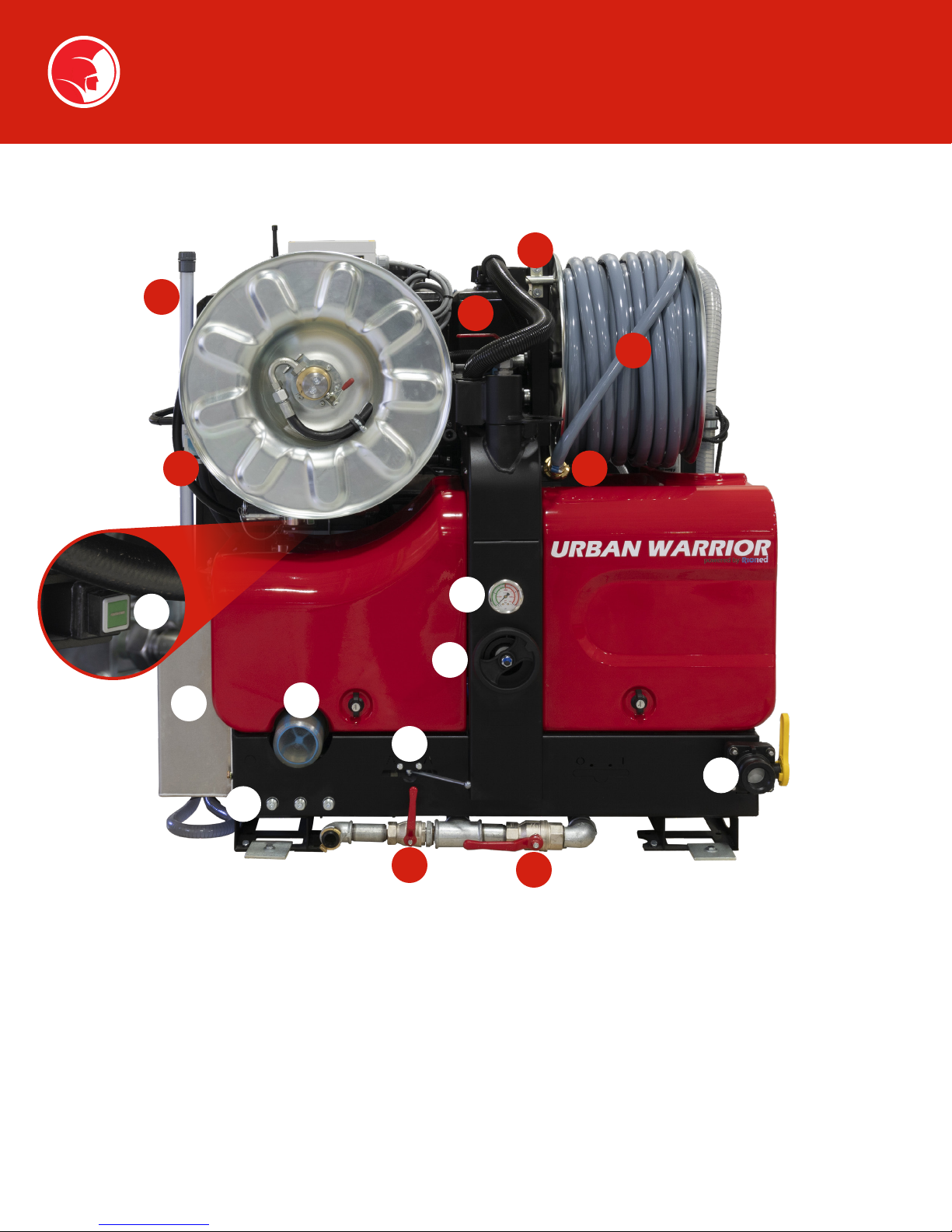
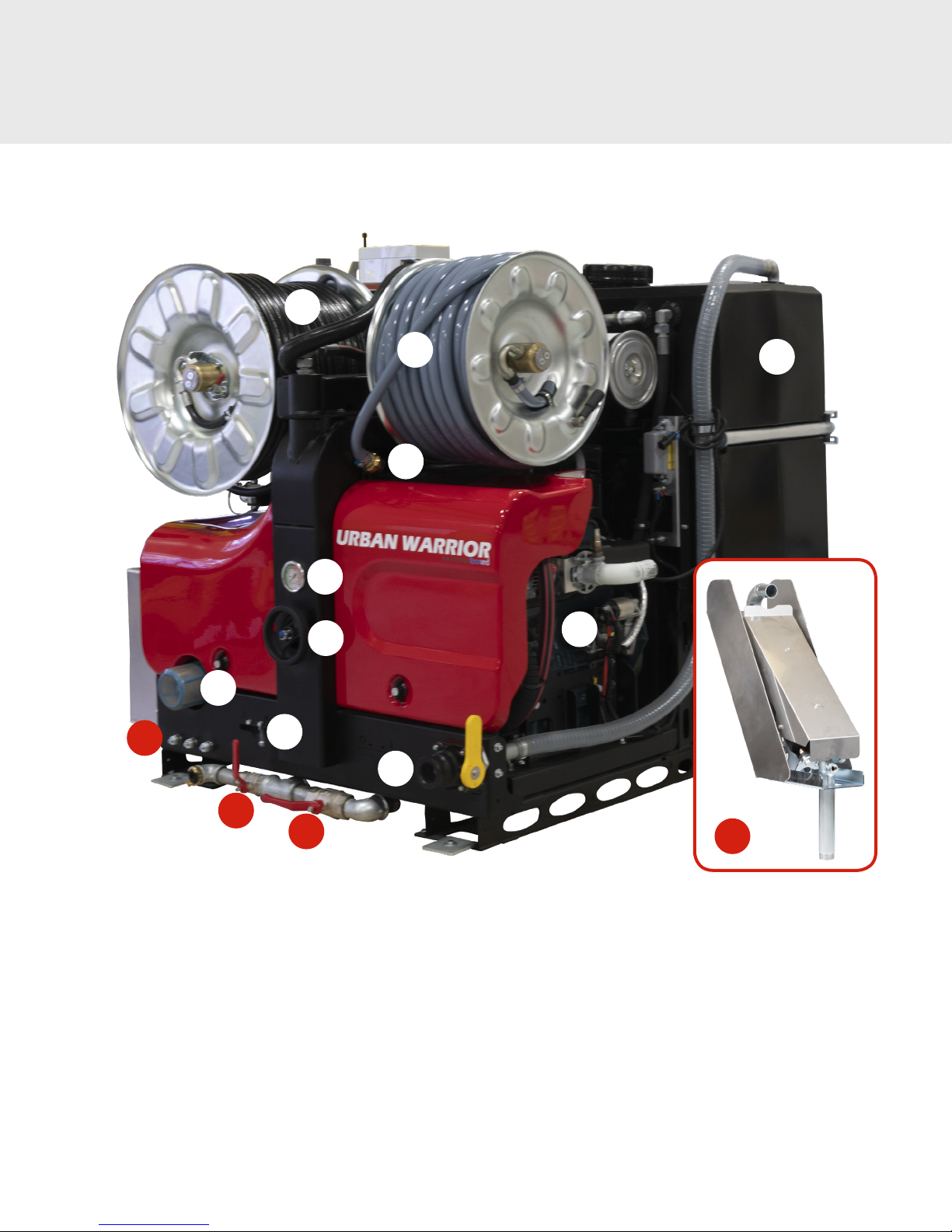
Description—Components
15
20
3
2
14
1
22
27
9
19
10
13
12
11
8
16
1. High-pressure hose on reel
2. Supply hose on reel
3. Supply hose valve
4. eController
5. Hose holder
6. Hose guide
7. High-pressure (HP) valve
8. Supply pipe
9. Water lter
10. Drain valve
6
11. Pressure regulator
12. Pressure gauge
13. Supply hose holder
14. Pivot Locking Device
15. Supply hose reel lock
16. Water lter valve
17. HP pump
18. Hydraulic oil reservoir
19. Pulsator valve
20. Water tank level indicator
21. Water tank
22. Fuel tank
23. Engine
24. Battery
25. ECM (Engine Control Module)
26. Hydraulic Hose Reel Speed
Control
27. Nozzle holders
28. Catalytic converter
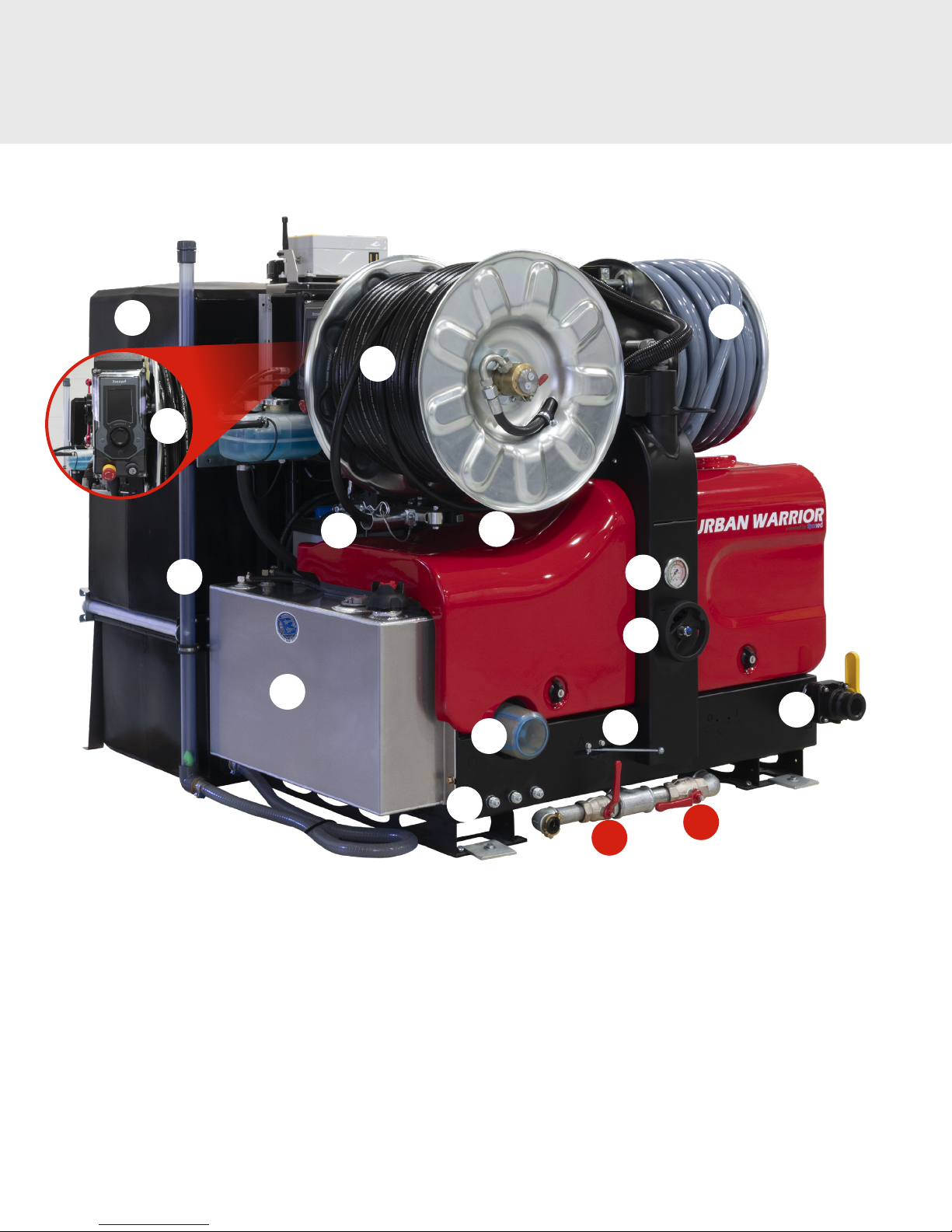
Description—Components
21
4
20
22
5
1
14
9
2
12
11
8
19
1. High-pressure hose on reel
2. Supply hose on reel
3. Supply hose valve
4. eController
5. Hose holder
6. Hose guide
7. High-pressure (HP) valve
8. Supply pipe
9. Water lter
10. Drain valve
27
11. Pressure regulator
12. Pressure gauge
13. Supply hose holder
14. Pivot Locking Device
15. Supply hose reel lock
16. Water lter valve
17. HP pump
18. Hydraulic oil reservoir
19. Pulsator valve
20. Water tank level indicator
16
10
21. Water tank
22. Fuel tank
23. Engine
24. Battery
25. ECM (Engine Control Module)
26. Hydraulic Hose Reel Speed
Control
27. Nozzle holders
28. Catalytic converter
7
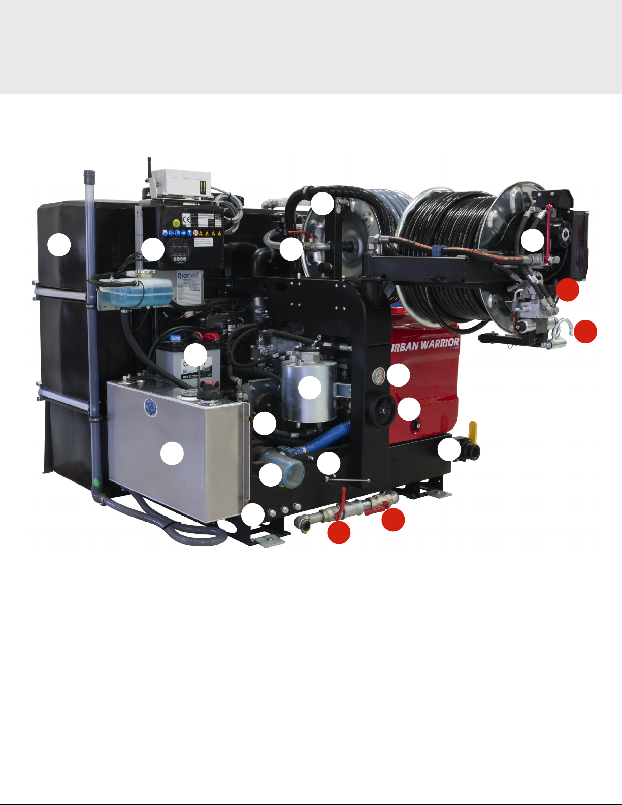
Description—Components
15
21
25
22
24
27
3
7
26
6
12
18
11
17
8
19
9
16
10
1. High-pressure hose on reel
2. Supply hose on reel
3. Supply hose valve
4. eController
5. Hose holder
6. Hose guide
7. High-pressure (HP) valve
8. Supply pipe
9. Water lter
10. Drain valve
8
11. Pressure regulator
12. Pressure gauge
13. Supply hose holder
14. Pivot Locking Device
15. Supply hose reel lock
16. Water lter valve
17. HP pump
18. Hydraulic oil reservoir
19. Pulsator valve
20. Water tank level indicator
21. Water tank
22. Fuel tank
23. Engine
24. Battery
25. ECM (Engine Control Module)
26. Hydraulic Hose Reel Speed
Control
27. Nozzle holders
28. Catalytic converter
1
Description—Components
27
9
19
12
11
13
8
2
21
23
10
16
1. High-pressure hose on reel
2. Supply hose on reel
3. Supply hose valve
4. eController
5. Hose holder
6. Hose guide
7. High-pressure (HP) valve
8. Supply pipe
9. Water lter
10. Drain valve
11. Pressure regulator
12. Pressure gauge
13. Supply hose holder
14. Pivot Locking Device
15. Supply hose reel lock
16. Water filter valve
17. HP pump
18. Hydraulic oil reservoir
19. Pulsator valve
20. Water tank level indicator
28
21. Water tank
22. Fuel tank
23. Engine
24. Battery
25. ECM (Engine Control Module)
26. Hydraulic Hose Reel Speed
Control
27. Nozzle holders
28. Catalytic converter
9
Description—Components
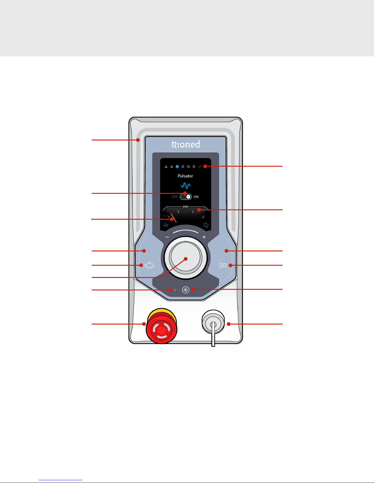
CONTROLS AND INDICATIONS
Corona
Function icon
Navigation bullets
Pointer
Engine LED
Engine On button
Navigator dial
Vacuum LED
Emergency stop
Tachometer
High pressure spray LED
High pressure spray button
Vacuum button
Key switch
(o / manual / Riomote)
10
Description—Controls
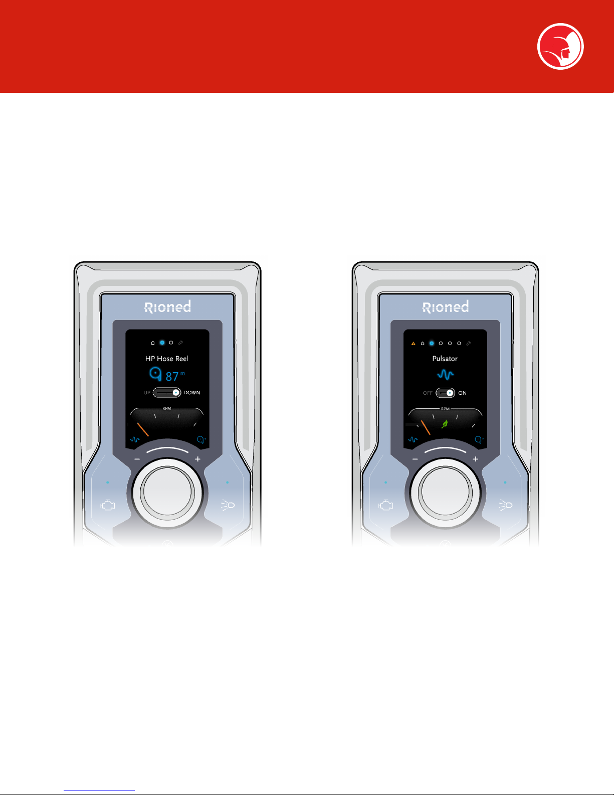
ECONTROLLER FUNCTIONS
Spartan Tool provides several options on the Urban Warrior skid mount sewer jetter. As a result, there are multiple eControl
configurations to accommodate the features available on any particular unit.
This section of the manual will cover available functions of the Two Function eController and the Three Function eController.
The two figures below identify the Two Function and Three Function eController.
2 FUNCTION ECONTROLLER
The two function remote is identified by the two
blue function indicators at the top of the LCD
display.
The two functions are:
• Home function
• Maintenance function
3 FUNCTION ECONTROLLER
The three function remote is identified by the three
blue function indicators at the top of the LCD
display.
The three functions are:
• Home function
• HP hose reel control
• Management function
11

Description—Controls
The Corona on the eController is normally off (gray).
CORONA DISPLAY
Blue corona indicates
set to Riomote Control
Red corona indicates
eController error
See page 27 (eController
Errors) for alarm functions
PUSH BUTTONS AND INDICATING LIGHTS
The Engine On light/button indicates the status and
controls the starting of the engine. (See page 19, Starting
the Engine, for more information.)
The High Pressure Spray light/button indicates the status
and controls the high pressure spray valve. (See page 24,
Cleaning a Drain Line, for more information.)
The Blue LED above each button will blink when the
corresponding function is available. (The engine is ready to start or
high pressure spray is available.)
The Blue LED above each button will light solid when the
corresponding function is active. (The engine is running or the high
pressure spray valve is open.)
Orange corona indicates
pre-start functions or
one of two error conditions:
• Run dry (no water
in tank)
• Error oil level
Insert key
Position 1
(manual control)
Position 2
(remote control)
12
Description—Controls
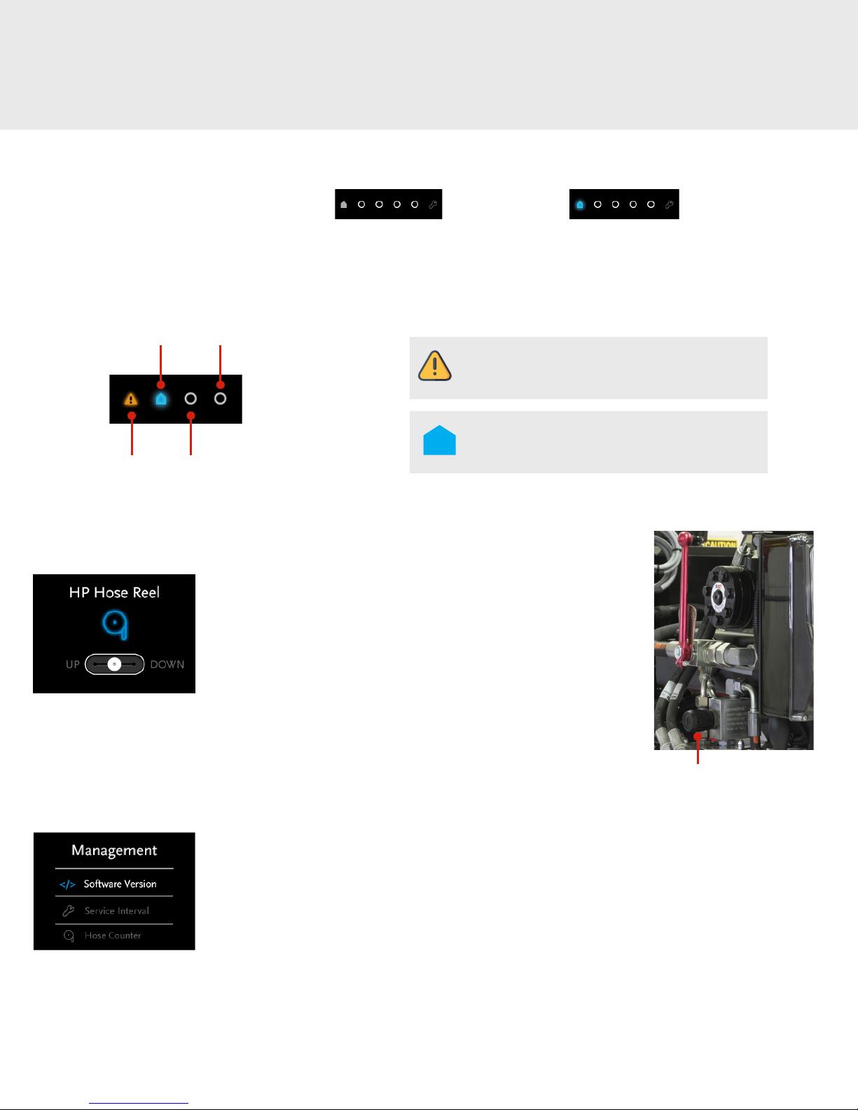
NAVIGATION BULLETS
The navigation bullets have two general states: Passive (gray) Active (blue)
Depending on the user’s location in the menu, one bullet is on display, or in the case of a pop-up eController error, all navigation bullets
disappear. (See page 27, eController Errors, for a list of pop-up displays.)
Features in navigation bullets are in specified order, if applicable:
Home
Error
Management
HP Hose
Reel
ECONTROLLER FUNCTIONS
HP Hose Reel Mode
When the eController is set to HP Hose Reel the LCD displays the
hose position and the up/down control positions. The hose reel is
actuated by rotating the Navigator dial clockwise to select down and
counter clockwise to select up. Depress the Navigator dial to select
the action.
The speed of the hydraulic drive using the eController is controlled
by adjusting the speed control unit which throttles the hydraulic flow
to the reel drive hydraulic motor. (See page 21, Rewind Hose Using
Hydraulic Reel.)
The Error navigation icon is only visible and can
be navigated when an error is applicable.
The Home navigation icon is the default position
and normally displays engine run time and HP
hose counter.
Hydraulic Speed Control
Management Mode
When the eController is set to Management Mode, the LCD displays a menu of three functions that can
be selected by rotating the Navigator dial and activated by depressing the navigation knob.
• Software Version displays the current version of the controller software.
• Service Interval displays the days and run hours until maintenance is required.
• Hose Counter displays the length of hose off the HP hose reel.
13

Description—Controls
Hose Counter (if equipped)
When the eController is set to Hose Counter mode, the LCD displays a menu of two functions that can
be selected by rotating the Navigator dial and activated by depressing the navigation knob.
• Hose Counter allows the user to select on or off.
• Counter Unit allows the user to select meters or feet.
Tachometer
The pointer indicates the engine’s current RPM.
14
 Loading...