

Spartan Tool URBAN WARRIOR SKID MOUNT JETTER, 75720010, Ultimate Urban Warrior Skid Mount Sewer Jetter, 75730010 Product Manual
FOR T OUGH CUSTOMERS.
SINCE 1943
PRODUCT MANUAL
Urban Warrior
Skid Mount Sewer Jetter
Spartan Tool LLC | 1506 West Division Street | Mendota, IL 61342
order by phone 800.435.3866 order online SpartanTool.com
© 2018 Spartan Tool LLC
Part #75720010

Contents
WARNINGS ............................................................................................................4
FEATURES .............................................................................................................5
DESCRIPTION—COMPONENTS .........................................................................................6
DESCRIPTION—CONTROLS ............................................................................................11
eController Functions ......................................................................................................... 11
Corona Display ............................................................................................................... 12
Push Buttons and Indicating Lights ............................................................................................ 12
Navigation Bullets ............................................................................................................ 13
HP Hose Reel Mode ........................................................................................................... 13
Management Mode ........................................................................................................... 13
Hose Counter (if equipped) ................................................................................................... 14
Tachometer .................................................................................................................. 14
Remote Control ............................................................................................................... 15
SAFETY INSTRUCTIONS ...............................................................................................16
IMPORTANT SYMBOLS ................................................................................................18
MECHANICAL OPERATION .............................................................................................19
Check Before Departure ...................................................................................................... 19
Placement of Urban Warrior ................................................................................................... 19
Prior to Starting the Urban Warrior ............................................................................................ 19
Starting the Engine ........................................................................................................... 20
Electric Hose Reel Pivot Locking Device ........................................................................................ 21
Hydraulic Reel Control ........................................................................................................ 22
High Pressure Hose Guide ..................................................................................................... 22
ECONTROLLER OPERATION ............................................................................................23
Management Mode ........................................................................................................... 23
Emergency Stop Test .......................................................................................................... 24
Battery Indication ............................................................................................................. 24
RIOMOTE® CONTROL OPERATION ......................................................................................24
2

OPERATING INSTRUCTIONS ...........................................................................................25
Cleaning a Drain Line ......................................................................................................... 25
Stop Spraying ................................................................................................................ 26
Care of the HP Hose ........................................................................................................... 26
Cold Weather Operation ...................................................................................................... 26
Cleaning a Wall, Terrace, or Floor .............................................................................................. 27
Secure After High-Pressure Cleaning .......................................................................................... 27
ECONTROLLER ERRORS ................................................................................................28
Emergency Stop .............................................................................................................. 28
Engine Temperature .......................................................................................................... 28
Heat Exchanger High Temperature ............................................................................................ 28
Hydraulic Oil High Temperature ............................................................................................... 29
Oil Level ...................................................................................................................... 29
Coolant Level ................................................................................................................. 29
Battery Charge ............................................................................................................... 30
Run Dry ...................................................................................................................... 30
Service Interval ............................................................................................................... 30
MAINTENANCE .......................................................................................................31
Daily Maintenance ............................................................................................................ 31
Minor Service ................................................................................................................. 32
Hydraulic System ............................................................................................................. 33
Extensive Periodic Maintenance ............................................................................................... 34
Maintenance Schedule ........................................................................................................ 34
TECHNICAL SPECIFICATIONS ..........................................................................................35
TROUBLESHOOTING ..................................................................................................37
APPENDIX A: ENGINE CONTROL MODULE .............................................................................39
APPENDIX B: MACHINE DIMENSIONS ..................................................................................40
APPENDIX C: ACCESSORIES ...........................................................................................41
3

Warnings
• Read the safety and operating instructions before using any Spartan Tool product. Drain and sewer cleaning can be dangerous if
proper procedures are not followed and appropriate safety gear is not utilized. Read the engine owners’ manual for instructions and
safety precautions on engine operation.
• Gasoline is extremely flammable and is explosive under certain conditions.
• Refuel in a well ventilated area with the engine stopped. Do not smoke or allow flames or sparks in the area where the engine is
refueled or where gasoline is stored.
• Do not overfill the fuel tank (there should be no fuel in the filler neck). After refueling, make sure the tank cap is closed properly
and securely.
• Explosive fuel can cause fires and severe burns. Fuel is flammable and its vapors can ignite. Store fuel only in approved containers, in
well ventilated, unoccupied buildings. Do not fill the fuel tank while the engine is hot or running, since spilled fuel could ignite if it
comes in contact with hot parts or sparks from ignition. Do not start the engine near spilled fuel. Never use fuel as a cleaning agent.
• Before starting unit, be sure to wear personal protective equipment such as safety goggles or face shield and protective clothing
such as gloves, coveralls or raincoat, rubber boots with metatarsal guards, and hearing protection.
• Ensure the jet hose has been placed in the pipe (minimum of 6 feet suggested) before engaging the water pressure to prevent the
hose from coming out of the pipe prematurely and causing injury.
• Always shut off the water pressure before pulling the hose out of the pipe. Mark the hose a minimum of 6 feet from the end to help
ensure the hose is not accidentally pulled out of the pipe while still under pressure. Shut off the water pressure when the hose mark
is encountered.
CAUTION: Portions of the system can still be under pressure even if the unit is not operating.
• Never point the wash gun at anyone while operating the unit. Injury may result.
• Drains and sewer can carry bacteria and other infectious micro-organisms or materials which can cause death or severe illness. Avoid
exposing eyes, nose, mouth, ears, hands, and cuts and abrasions to waste water or other potentially infectious materials during drain
and sewer cleaning operations. To further help protect against exposure to infectious materials, wash hands, arms and other areas
of the body, as needed, with hot, soapy water and, if necessary, flush mucous membranes with water. Also, disinfect potentially
contaminated equipment by washing such surfaces with a hot soapy wash using a strong detergent.
• For any questions, contact Spartan Tool at the address shown below.
CONTACT US
Spartan Tool LLC
1506 West Division Street
Mendota, IL 61342
800.435.3866
SpartanTool.com
4

SPECS
• Pipe Sizes: up to 18" diameter
• Max Water Pressure: 3,000 psi
• Max Water Flow: 19 GPM
• Water Capacity: 160 gallons
• Unit Weight: 1,200 lbs (empty)
• Overall Size: 52/"L x 49"W x 49/"H
• Warranty: (1) year limited
FEATURES
• 50 HP Kubota Gasoline Engine
Features
• P52 Speck/Giant Triplex Pump
• eControl: LCD screen and easy-to-use jog-wheel for single click operation of machine
• LED dispay and warning lights provide machine status at a glance
• Pressure can be continuously adjusted with accessible handwheel
• Hose length counter
• Remote control
• 1/2" x 360' of Maxflow HP hose
• 115' of supply hose
• Pivoting 180° hose reel, hydraulically operated with freewheel system
• Powder coated steel frame
SAFETY
• Run dry protection with override ability
• Automatic engine shutdown protection for high water temperature, engine temperature, low engine oil, or low engine coolant
• Electric reel latching mechanism for easy pivoting and safety
5
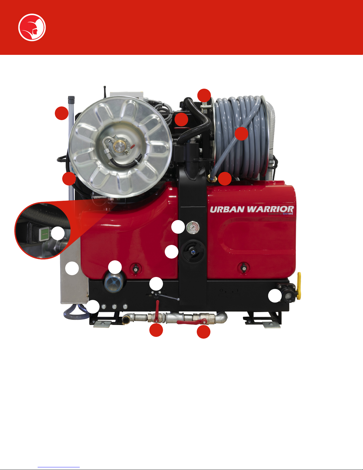
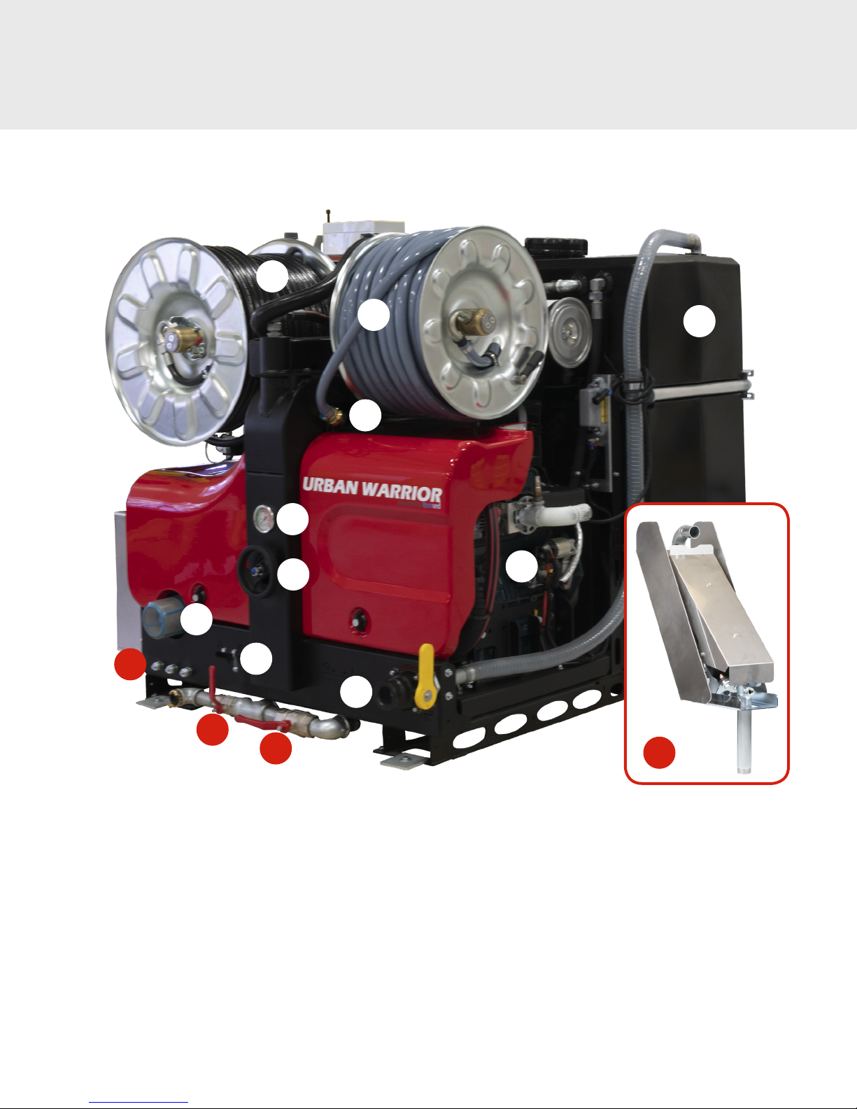
Description—Components
15
20
3
2
14
1
22
27
9
19
10
13
12
11
8
16
1. High-pressure hose on reel
2. Supply hose on reel
3. Supply hose valve
4. eController
5. Hose holder
6. Hose guide
7. High-pressure (HP) valve
8. Supply pipe
9. Water lter
10. Drain valve
6
11. Pressure regulator
12. Pressure gauge
13. Supply hose holder
14. Pivot Locking Device
15. Supply hose reel lock
16. Water lter valve
17. HP pump
18. Hydraulic oil reservoir
19. Pulsator valve
20. Water tank level indicator
21. Water tank
22. Fuel tank
23. Engine
24. Battery
25. ECM (Engine Control Module)
26. Hydraulic Hose Reel Speed
Control
27. Nozzle holders
28. Catalytic converter
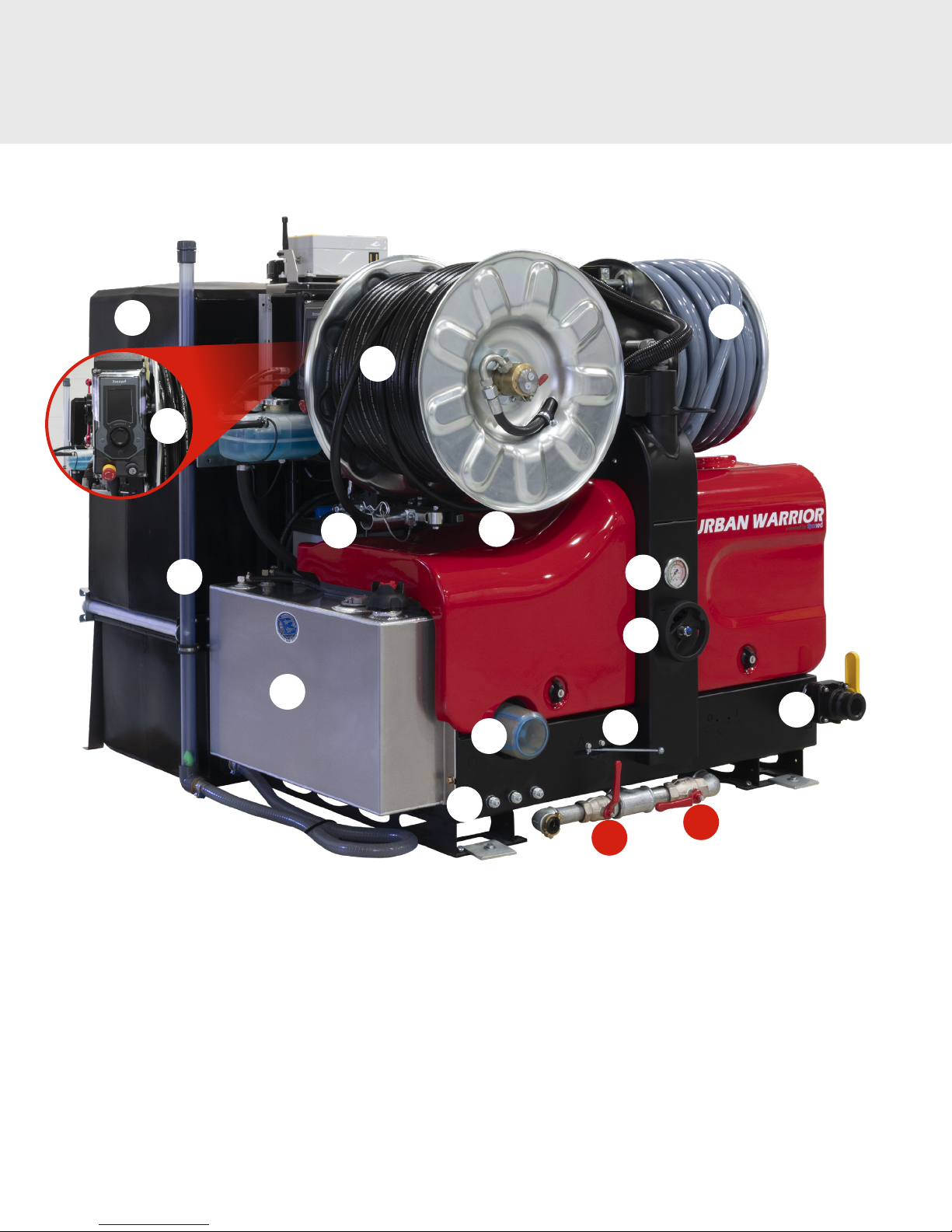
Description—Components
21
4
20
22
5
1
14
9
2
12
11
8
19
1. High-pressure hose on reel
2. Supply hose on reel
3. Supply hose valve
4. eController
5. Hose holder
6. Hose guide
7. High-pressure (HP) valve
8. Supply pipe
9. Water lter
10. Drain valve
27
11. Pressure regulator
12. Pressure gauge
13. Supply hose holder
14. Pivot Locking Device
15. Supply hose reel lock
16. Water lter valve
17. HP pump
18. Hydraulic oil reservoir
19. Pulsator valve
20. Water tank level indicator
16
10
21. Water tank
22. Fuel tank
23. Engine
24. Battery
25. ECM (Engine Control Module)
26. Hydraulic Hose Reel Speed
Control
27. Nozzle holders
28. Catalytic converter
7
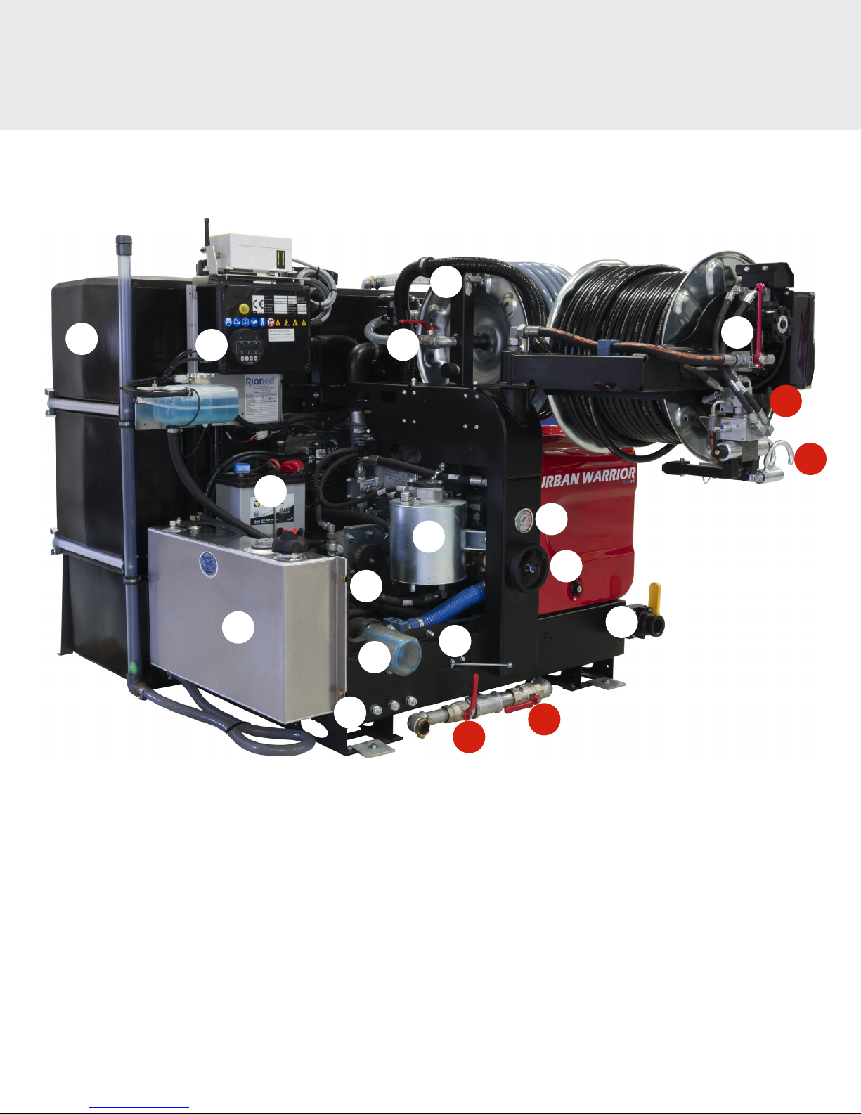
Description—Components
15
21
25
22
24
27
3
7
26
6
12
18
11
17
8
19
9
16
10
1. High-pressure hose on reel
2. Supply hose on reel
3. Supply hose valve
4. eController
5. Hose holder
6. Hose guide
7. High-pressure (HP) valve
8. Supply pipe
9. Water lter
10. Drain valve
8
11. Pressure regulator
12. Pressure gauge
13. Supply hose holder
14. Pivot Locking Device
15. Supply hose reel lock
16. Water lter valve
17. HP pump
18. Hydraulic oil reservoir
19. Pulsator valve
20. Water tank level indicator
21. Water tank
22. Fuel tank
23. Engine
24. Battery
25. ECM (Engine Control Module)
26. Hydraulic Hose Reel Speed
Control
27. Nozzle holders
28. Catalytic converter
1
Description—Components
27
9
19
12
11
13
8
2
21
23
10
16
1. High-pressure hose on reel
2. Supply hose on reel
3. Supply hose valve
4. eController
5. Hose holder
6. Hose guide
7. High-pressure (HP) valve
8. Supply pipe
9. Water lter
10. Drain valve
11. Pressure regulator
12. Pressure gauge
13. Supply hose holder
14. Pivot Locking Device
15. Supply hose reel lock
16. Water filter valve
17. HP pump
18. Hydraulic oil reservoir
19. Pulsator valve
20. Water tank level indicator
28
21. Water tank
22. Fuel tank
23. Engine
24. Battery
25. ECM (Engine Control Module)
26. Hydraulic Hose Reel Speed
Control
27. Nozzle holders
28. Catalytic converter
9
Description—Components
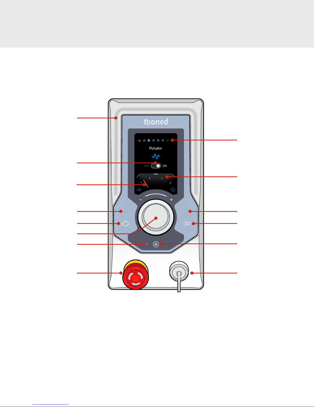
CONTROLS AND INDICATIONS
Corona
Function icon
Navigation bullets
Pointer
Engine LED
Engine On button
Navigator dial
Vacuum LED
Emergency stop
Tachometer
High pressure spray LED
High pressure spray button
Vacuum button
Key switch
(o / manual / Riomote)
10
Description—Controls
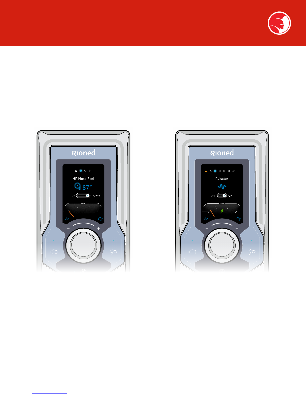
ECONTROLLER FUNCTIONS
Spartan Tool provides several options on the Urban Warrior skid mount sewer jetter. As a result, there are multiple eControl
configurations to accommodate the features available on any particular unit.
This section of the manual will cover available functions of the Two Function eController and the Three Function eController.
The two figures below identify the Two Function and Three Function eController.
2 FUNCTION ECONTROLLER
The two function remote is identified by the two
blue function indicators at the top of the LCD
display.
The two functions are:
• Home function
• Maintenance function
3 FUNCTION ECONTROLLER
The three function remote is identified by the three
blue function indicators at the top of the LCD
display.
The three functions are:
• Home function
• HP hose reel control
• Management function
11

Description—Controls
The Corona on the eController is normally off (gray).
CORONA DISPLAY
Blue corona indicates
set to Riomote Control
Red corona indicates
eController error
See page 27 (eController
Errors) for alarm functions
PUSH BUTTONS AND INDICATING LIGHTS
The Engine On light/button indicates the status and
controls the starting of the engine. (See page 19, Starting
the Engine, for more information.)
The High Pressure Spray light/button indicates the status
and controls the high pressure spray valve. (See page 24,
Cleaning a Drain Line, for more information.)
The Blue LED above each button will blink when the
corresponding function is available. (The engine is ready to start or
high pressure spray is available.)
The Blue LED above each button will light solid when the
corresponding function is active. (The engine is running or the high
pressure spray valve is open.)
Orange corona indicates
pre-start functions or
one of two error conditions:
• Run dry (no water
in tank)
• Error oil level
Insert key
Position 1
(manual control)
Position 2
(remote control)
12
Description—Controls
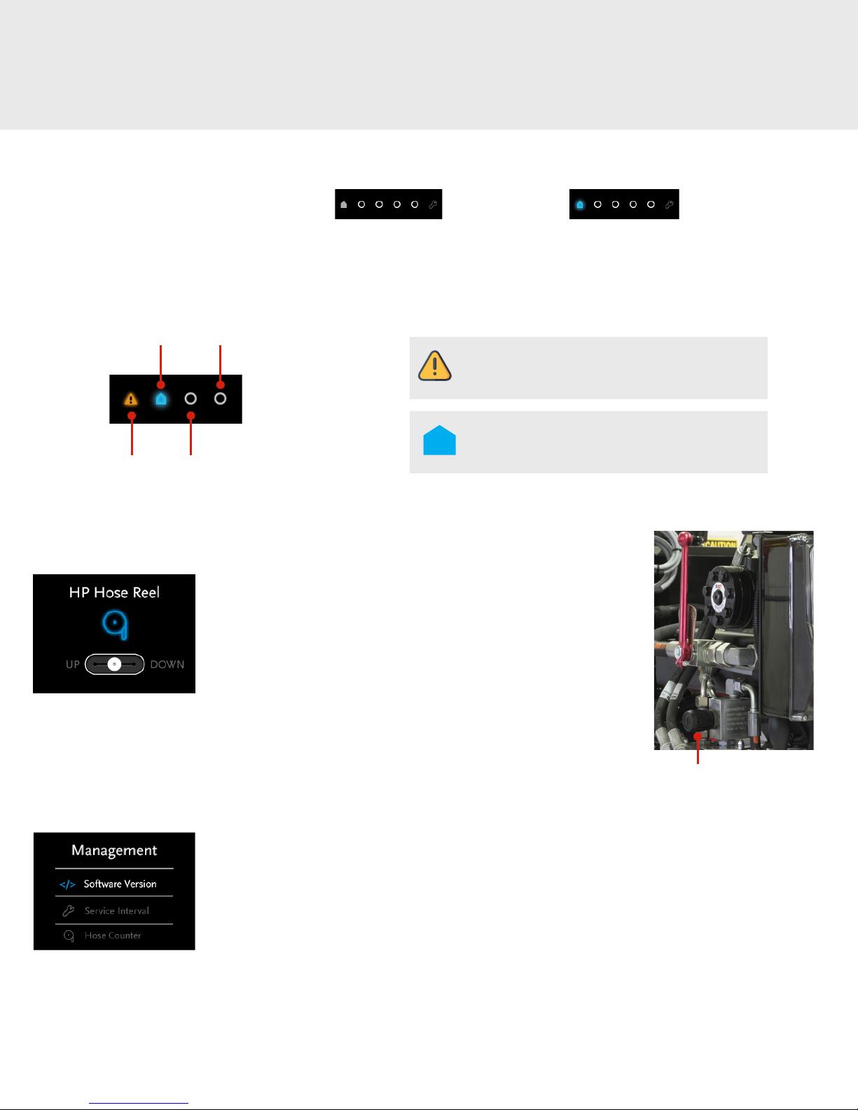
NAVIGATION BULLETS
The navigation bullets have two general states: Passive (gray) Active (blue)
Depending on the user’s location in the menu, one bullet is on display, or in the case of a pop-up eController error, all navigation bullets
disappear. (See page 27, eController Errors, for a list of pop-up displays.)
Features in navigation bullets are in specified order, if applicable:
Home
Error
Management
HP Hose
Reel
ECONTROLLER FUNCTIONS
HP Hose Reel Mode
When the eController is set to HP Hose Reel the LCD displays the
hose position and the up/down control positions. The hose reel is
actuated by rotating the Navigator dial clockwise to select down and
counter clockwise to select up. Depress the Navigator dial to select
the action.
The speed of the hydraulic drive using the eController is controlled
by adjusting the speed control unit which throttles the hydraulic flow
to the reel drive hydraulic motor. (See page 21, Rewind Hose Using
Hydraulic Reel.)
The Error navigation icon is only visible and can
be navigated when an error is applicable.
The Home navigation icon is the default position
and normally displays engine run time and HP
hose counter.
Hydraulic Speed Control
Management Mode
When the eController is set to Management Mode, the LCD displays a menu of three functions that can
be selected by rotating the Navigator dial and activated by depressing the navigation knob.
• Software Version displays the current version of the controller software.
• Service Interval displays the days and run hours until maintenance is required.
• Hose Counter displays the length of hose off the HP hose reel.
13

Description—Controls
Hose Counter (if equipped)
When the eController is set to Hose Counter mode, the LCD displays a menu of two functions that can
be selected by rotating the Navigator dial and activated by depressing the navigation knob.
• Hose Counter allows the user to select on or off.
• Counter Unit allows the user to select meters or feet.
Tachometer
The pointer indicates the engine’s current RPM.
14

REMOTE CONTROL
Hand-Held Remote Sender
Description—Controls
Hose UP/DOWN
(9-channel option)
Engine speed SLOW
Spray valve OFF
Engine OFF
Battery indication
Emergency stop
Engine speed FAST
Spray valve ON
Engine START
Remote pairing
The Riomote® radio remote control consists of a large waterproof and shockproof hand-held
sender and a unit-mounted receiver. The system is provided with separate batteries (8 hours per
charge) and is supplied with a battery charger. The Riomote® radio remote control is available in
7-channel and 9-channel models dependent on the functions available on the eController.
UNIT-MOUNTED RECEIVER
15

Safety Instructions
WARNING: Read the Operator’s Manual thoroughly before using any Spartan Tool product.
Drain and sewer cleaning can be dangerous if proper procedures are not followed. Know the proper
operation, correct applications for your Spartan Tool products
EMERGENCY STOP
This machine is equipped with an Emergency Stop. By operating the Emergency Stop, the machine will shut down. Do not use this
button for normal stopping. Only use it when dangerous situations occur. After use, remove the danger and then rotate the Emergency
Stop button clockwise to be able to start up again. Ensure the Emergency Stop can always be reached.
PRESSURE REGULATOR
The Pressure Regulator functions to ensure that the working pressure never gets too high. It functions like a safety valve, relieving
water to the storage tank to reduce pressure in the HP hose line.
PERSONAL PROTECTIVE EQUIPMENT
The following personal protective equipment should be worn by personnel operating or working with the Urban Warrior:
• Ear protection
• Protective safety glasses or goggles
• Gloves (recommended)
• Waterproof work clothing (recommended)
• Spray boots for use with the spray gun (recommended)
WORK AREA
The following precautions must be observed when establishing a work area for use of the Urban Warrior:
• Clearly mark the work area.
• Maintain a minimum distance of 20 feet from the work area.
• Remove all loose materials from inside the work area.
• Never spray from an unstable surface (ladder, boat, scaffold, etc.).
• Never use in a confined space (closed room).
• Ensure there are no combustible materials in the area.
• The area must be adequately ventilated to prevent accumulation of carbon monoxide.
• DO NOT use corrosive chemicals in conjunction with Spartan Tool sewer jetters. Only environmentally-approved chemicals should
be introduced into drain lines.
16

Safety Instructions
GENERAL PRECAUTIONS
• Do not let the machine operate without supervision.
• Keep children and animals away from the machine.
• DO NOT spray on humans or animals. If the skin is penetrated, immediately seek medical attention.
• Prevent damage from debris or flying parts.
• Avoid spraying near electrical connections and other electric components if you are cleaning with a spray gun.
• Never block the controls in any way.
• Put personal protective equipment on BEFORE you start the machine.
• Ensure that the spray nozzle does not leave the drain.
SAFETY STICKERS
1. Safety glasses, hard hats , and hearing protection are required
2. Safety shoes are required
3. Be familiar with the user’s manual
4. Hand protection is required
5. Wear protective clothing against caustic material
6. No eating or drinking
7. Slipping hazard
8. Pinching hazard (hand injury)
9. Rotating machinery
10. Warning, machine auto start
17

Important Symbols
PRESSURE GAUGE
Operating Zone Danger Zone
The mechanical relief in the
unloader valve will prevent
pressure from exceeding
3000 PSI.
WARNING If the unit fails to maintain pressure within the operating zone, contact Spartan Tool
Customer Service at 800.435.3866 or by email at CustomerService@SpartanTool.com.
18

Mechanical Operation
CHECK BEFORE DEPARTURE
Before you drive away with the vehicle, check the following:
1. The high-pressure hose has been inserted into the hose holder (5) and secured with
the locking pin.
2. The high-pressure hose reel is locked with the clutch engaged (30) (see page 21)
and the manual hydraulic hose reel control lever is in the neutral position, or the
eController is not in Hose Reel mode. (See page 21, Hydraulic Hose Reel Control, for
more information.) The HP reel swing arm is locked in place with latch.
3. The supply hose is connected to the supply hose holder (19). The supply hose reel is
locked by means of the reel locking device (15).
4. If temperatures are below freezing, the water tank should be emptied and the piping
system drained and flushed with antifreeze. (See page 25, Cold Weather Operation, for
more information.)
5. The vehicle is now ready for departure.
PLACEMENT OF URBAN WARRIOR
1. Put the vehicle at the desired location and set the parking brake.
2. Block the tires if using on an incline or uneven surface.
3. Mark the working area by establishing barriers to prevent inadvertent access to the
work area.
PRIOR TO STARTING THE URBAN WARRIOR
5
15
19
1. Ensure there is adequate fuel in the fuel tank (22) for the intended task.
2. Ensure the water filter (9) is clean. Clean the filter, if necessary.
3. Check that the supply valve (16) to the water filter is open.
4. Check that the high-pressure valve (7) at the HP hose reel is closed.
5. Fill the water tank via the supply pipe (8) or the supply hose.
(The maximum water temperature is 55°C.)
6. Loosen the control wheel of the pressure regulator (11) (rotate
counter-clockwise).
7. Attach the jetting
nozzle onto the
high-pressure hose.
7
22
11
9
8
16
19

Mechanical Operation
STARTING THE ENGINE
IMPORTANT! The machine is equipped with an Emergency Stop. By
operating this Stop, the machine will shut down. Do not use this button for
normal stopping. Only use when dangerous situations occur. After use, rotate the
Emergency Stop clockwise to be able to start again. Make sure the Emergency
Stop can always be reached.
CAUTION! Put on protective safety goggles and ear protection
before starting the machine.
1. Put the key in the eController key switch.
2. Turn the key clockwise to position 1, Manual Control on.
• Work Safe is displayed for 2 seconds.
• Icon Manual Control on is displayed for 2 seconds.
• Then the main menu is displayed.
3. Check the Error icon.
• If the error icon is visible, then check the eController Error
icon. (See page 27 for a description of eController Errors.)
20

Mechanical Operation
38
39
4. If the error icon is not visible, depress the Engine On button for two seconds.
• After 5 seconds, the engine starts.
• With the engine running, the blue Engine LED light (38) and the Engine On light (39) is
displayed for 2 seconds.
• The main menu on the eController is displayed after 5 seconds.
5. Increase (clockwise) or decrease (counter clockwise) RPM by turning the Navigator dial.
6. Depress the Navigator dial to display the Navigation Bullet menu.
• Let the engine warm up. After 3 minutes, the machine is ready for use.
• Press the Engine On button (39) to adjust RPMs with the Navigator dial.
ELECTRIC HOSE REEL PIVOT
LOCKING DEVICE
There are two locking mechanisms associated with the high
pressure hose reel arm.
1. Electric Push Button
2. Manual Pull Cable
1
2
21

Mechanical Operation
HYDRAULIC REEL CONTROL
The hydraulic control lever is spring loaded to default to the Neutral
Position (A) where the hose reel is locked by the hydraulic actuator.
• Pushing the control lever up (position B) will actuate the hydraulic
motor to wind the hose onto the reel.
• Pushing the control lever down (position C) will actuate the hydraulic
motor to unwind the hose off the reel.
• Due to the proportional functioning of this valve you can control the
speed of the reel by movement of the lever away from the center
position (A).
• Pushing the control level into position D, (a maintaining position) will
allow the hose reel to move without the aid of the hydraulic motor. This
allows the hose to unwind as the high pressure hose nozzle works its
way through a drain line.
A clutch assembly (30) on the HP hose reel drive unit can be disengaged to
allow the hose reel to free wheel for pulling the hose off the reel manually.
The hydraulic speed control knob (26) can be adjusted to control
the range of speed when using the hydraulic reel control lever. (This feature
is only available on model equipped with the 9-channel remote.)
(if equipped)
26
9-channel remote
30
For 5-channel remote with
WARNING! Never block the Hydraulic Hose Reel lever and always control it with one hand while
guiding the high-pressure hose by means of the hose guide.
HIGH PRESSURE HOSE GUIDE
The purpose of the High-Pressure Hose Guide (6) is to guide the HP hose
onto and off of the hose reel.
• Put the end of the HP hose through the opening of the hose guide (6).
• Moving the hose guide right and left guides the hose evenly on the
hose reel.
manual hydraulic valve
D
B
A
C
6
22

eController Operation
MANAGEMENT MODE
Management Mode functions to display the current software version, required service intervals, and the
hose reel counter.
1. Rotate the Navigator dial to set the navigation bullet to the last position, Management.
2. Depress the Navigator dial to activate the Management function.
• The Navigation bullet extinguishes.
• The Management underline illuminates.
3. Once the Management function is activated, the three menu options are displayed which include:
Software version, Service interval and Hose counter.
4. Each menu item can be displayed by selecting the item with the Navigator dial and depressing the dial
to activate the selection.
23

Riomote® Control Operation
RIOMOTE® CONTROL
The Riomote® remote control provides the ability to operate the high pressure machine jetter from a
distance. There are multiple versions of the remote control based on the available functions of the machine.
Corona
EMERGENCY STOP TEST
Check that the emergency stop works before working with
the Riomote® control. Proceed as follows:
1. Insert the key into the eController key switch.
2. Turn the key to position 2, Remote Control on.
• Work Safe is displayed for 2 seconds.
• Riomote® Control on is displayed continuously.
• Corona illuminates blue and is blinking.
3. Switch the Riomote® control on.
• Press and hold the Start button on the Riomote® to
link the Riomote® with the Urban Warrior.
• Release the Start button when the blue corona
stops blinking.
• Corona illuminates continuous blue when the
Riomote® control is in contact with the receiver.
4. Start the engine using Engine Start button on the
Riomote® control.
5. Depress the Stop button to exercise the Emergency
Stop function.
BATTERY INDICATION
If the Battery indicator on the Riomote control lights
continuously, the battery must be recharged.
NOTE! The engine will
shut down if the remote is
out of range or the battery
loses charge.
Battery
indicator
eController
key switch
1
2
Emergency stop
Engine start
Start
NOTE! If the engine does NOT stop by using the Riomote® control, contact Spartan Tool
Customer Service.
24

Operating Instructions
CLEANING A DRAIN LINE
1. Attach a suitable nozzle onto the high-pressure hose.
2. With the hose reel out of gear (Position D, page 21), pull the hose through the hose
guide (6) to facilitate guiding the hose.
3. The hose can be unwound short distances with the hydraulic hose reel out of gear.
4. Put the nozzle into the drain to be cleaned (a minimum of 6 feet).
5. Rotate the pressure regulator (11) clockwise to increase pressure to the desired
value on the pressure gauge (12).
6. Open the high-pressure valve (7).
7. Depress the high pressure on button
(35).
• Water begins spraying out of the
nozzle at the end of the hose.
• High pressure LED (33) lights blue.
• High Pressure On is displayed on the
eController screen for 2 seconds.
• After 5 seconds, Main Menu is
displayed on the eController screen.
12
11
8. Increase or decrease engine RPM by
turning the Navigator dial.
9. The hose will now unwind and work its
way into the drain line.
10. When possible, jet the drain line from
the low end to the high end of the pipe.
6
7
11. Check for water draining away as an
indication that the blockage has been
cleared in the drain line.
12. When the blockage has been cleared,
continue to flush the pipe while
rewinding the high-pressure hose.
33
35
Navigator dial
25

Operating Instructions
ATTENTION! Ensure that the spraying nozzle does not leave the drain while spraying.
Water under high pressure may cause severe injury.
STOP SPRAYING
Depress the high pressure button (35) to shut the high pressure valve.
• The high pressure LED (33) extinguishes.
• High Pressure O appears on the eController display for 2 seconds.
• Water spray at hose nozzle stops.
• Engine RPM decreases.
• Close the high pressure valve (7).
33
35
CARE OF THE HP HOSE
• Always clean the hose after use.
• Ensure there are no sharp objects near the hose.
• Ensure vehicles do not cross over the hose.
IMPORTANT! Rewind hose onto reel under pressure to avoid crushing. If machine has run out
of water, ensure hose is unwound before pressurizing.
COLD WEATHER OPERATION
Your high-pressure device may freeze up in cold weather and temperatures below 32°F. A number of safety precautions must be taken.
Additional preparations before departure:
1. Drain the water tank by opening the drain valve.
2. When all the water has been removed or drained, remove the water filter.
3. Clean the filter and mount it in opposite order.
4. Close the drain valve.
5. Remove the nozzle/gun from the HP hose.
6. Antifreeze unit with optional Antifreeze System.
26

CLEANING A WALL, TERRACE, OR FLOOR
CAUTION! Before using a spray gun, set the jetter pressure below the maximum spray gun
pressure (+/- half the maximum spray gun pressure). Do this prior to starting the engine. Once the
engine is running, jetter pressure can be increased by turning the HP regulator handwheel to the
working pressure. DO NOT exceed the green band pressure on the pressure gauge.
1. Attach the spray gun (B) onto the high-pressure hose.
2. Disengage the clutch and completely unroll the high pressure hose.
3. Attach the spray lance gun (C), securing the quick coupling tightly.
4. Open the manual HP valve (7).
Operating Instructions
7
5. Depress the High Pressure On button.
6. Throttle up the engine speed by rotating the Navigator dial clockwise.
7. Rotate the pressure regulator hand wheel (11) clockwise until the desired
operating pressure is reached when the spray gun is open.
11
SECURE AFTER HIGH-PRESSURE CLEANING
1. Depress the high pressure button (35) to shut the high-pressure valve and throttle
down the engine.
2. Close the manual high pressure valve (7).
B C
34
35
3. Depress the Engine On button (34) for more than 1 second to stop the engine.
4. Rewind the hose.
IMPORTANT! Rewind hose onto reel under pressure to avoid crushing. If machine has run out
of water, ensure hose is unwound before pressurizing.
27

eController Errors
EMERGENCY STOP
1. The Emergency Stop icon illuminates on the eController when the Emergency Stop
button is depressed.
• Engine stops
• High pressure valve closes
• Pulsator valve closes (if equipped)
• Hose reel switches off
2. Operation can only be restarted after rotating the Emergency Stop button to release it.
ENGINE TEMPERATURE
1. The Engine Temperature icon illuminates when high engine temperature is detected
(240° F).
• Engine stops
• High pressure valve closes
• Pulsator valve closes (if equipped)
• Hose reel switches off
2. The operator can acknowledge the alarm display by depressing the Navigator dial in
Manual Mode.
3. Operation can only resume after engine temperature has cooled to clear the alarm.
HEAT EXCHANGER HIGH TEMPERATURE
1. The Heat Exchanger High Temperature icon illuminates when high temperature is
detected.
• Engine stops
• High pressure valve closes
• Pulsator valve closes (if equipped)
• Hose reel switches off
28
2. The operator can acknowledge the alarm display by depressing the Navigator dial in
Manual Mode.
3. Operation can only resume after heat exchanger temperature has cooled.

eController Errors
HYDRAULIC OIL HIGH TEMPERATURE
1. The Hydraulic Oil Temperature icon illuminates when high hydraulic oil temperature
is detected.
• Engine stops
• High pressure valve closes
• Pulsator valve closes (if equipped)
• Hose reel switches off
2. The operator can acknowledge the alarm display by depressing the Navigator dial in
Manual Mode.
3. Operation can only resume after the hydraulic oil temperature has cooled.
OIL LEVEL
1. The Oil Level icon illuminates when low engine oil level is detected.
• Engine stops
• High pressure valve closes
• Pulsator valve closes (if equipped)
• Hose reel switches off
2. The operator can override the alarm display by depressing the Navigator dial in Manual
Mode and continue operation.
COOLANT LEVEL
1. The Coolant Level icon illuminates when low engine coolant level is detected.
• Engine stops
• High pressure valve closes
• Pulsator valve closes (if equipped)
• Hose reel switches off
2. The operator can acknowledge the alarm display by depressing the Navigator dial in
Manual Mode.
3. The operator must refill the coolant level in order to restart the engine.
29

eController Errors
BATTERY CHARGE
1. The Battery Charge icon illuminates when low battery voltage is detected.
• Engine stops
• High pressure valve closes
• Pulsator valve closes (if equipped)
• Hose reel switches off
2. The operator can override the alarm display by depressing the Navigator dial in Manual
Mode and continue operation.
RUN DRY
1. The Run Dry icon illuminates when low level is detected in the water tanks.
• Engine stops
• High pressure valve closes
• Pulsator valve closes (if equipped)
• Hose reel switches off
2. The operator can override the alarm display by depressing the
Navigator dial in Manual Mode and continue operation.
3. The High-Pressure LED starts blinking when the run dry is active.
The override remains active as long as the Navigator dial is depressed.
SERVICE INTERVAL
1. The Service Interval icon illuminates when any of the maintenance intervals have
been exceeded. The error is also listed under the Management function on the
eController.
• Engine stops
• High pressure valve closes
• Pulsator valve closes (if equipped)
• Hose reel switches off
30
2. After running 360 days or 250 hours (whichever comes first), the error message is
displayed.
3. The operator can override the message by depressing the Navigator dial in Manual
Mode.
4. The message will reappear the next time the machine is started.

Maintenance
CAUTION! Always stop the engine first and depressurize the system before servicing or
repairing the machine. To depressurize the system, open the manual HP valve. If the spray gun is
attached, you must also pull the trigger to release the pressure.
DAILY MAINTENANCE
Check Oil Levels
• Check all oil levels once a week (engine oil, HP water pump oil, hydraulic oil).
• Add oil if necessary (see page "MOTOR" on page 35, Technical Specications, Motor).
• If oil level has dropped, this implies a leak in the system. In this case, check all gaskets, couplings, and hydraulic hoses in
the system.
• Immediately repair damage and fill the system with the correct oil.
NOTE! During the break-in period, oil consumption may be greater than usual.
Engine Oil Hydraulic Oil HP Water Pump Oil
Clean the Water Filter
1. Close the water lter valve (16).
2. Unscrew the cap from the lter piece (9).
3. Clean the filter and associated parts. After cleaning, assemble
the parts in reverse order.
9
4. Open the water lter valve (16).
5. Check for leakage.
16
31

Maintenance
MINOR SERVICE
Minor service must be carried out every 250 working hours (or at least once every 6 months) and includes the following parts of
the machine:
1. Drive and Engine
• Change the oil in the engine.
• Replace the oil filter.
• Clean the air filter.
• Replace the fuel filter.
• Check tension of the V-belt and increase tension if necessary.
• Check the condition of the battery.
• Check the torque of attachment bolts for the engine and tighten as necessary.
2. Carriage
• Lubricate all mechanical moving parts in the system. Check that all nuts and bolts have been correctly tightened.
3. Pump system
a. Cleaning the high-pressure control system:
• With the manual high-pressure valve closed, the pressure gauge should NOT indicate any pressure due to recirculation
through the unloader valve.
• If the spray gun is connected and closed, the pressure gauge should NOT indicate any pressure due to recirculation through
the unloader valve.
• If the pressure gauge does indicate a pressure, this implies a leakage in the system or the pop-off valve on the unloader valve
may be dirty or damaged. (Contact Spartan Tool Customer Service for assistance.)
• If leakage is suspected, stop the machine, unscrew the hose coupling and clean or replace the pop-off valve on the unloader.
Also, check the condition of the O-ring and gasket. (Contact Spartan Tool Customer Service for assistance.)
b. Regularly clean the high-pressure control system:
• Carefully remove all dirt.
• Proper maintenance will increase the service life of this part.
c. Changing the pump oil:
• Change the pump oil in the high-pressure pump after every 500 working hours (or at least once a year).
32

HYDRAULIC SYSTEM
IMPORTANT! Renew the hydraulic oil at least once a year!
1. Replace the hydraulic fluid in the reel drive system.
2. Check hydraulic oil level before each use. If level is not sufficient proceed as follows:
a. Stop the machine.
b. Ensure the unit is on a level surface.
c. Remove the dipstick (A) from the oil tank (B).
d. Clean the dipstick with a lint-free rag.
e. Put the dipstick back into the oil tank.
f. Remove the dipstick and check the oil on the dipstick is between maximum and minimum (C).
g. Fill oil, if necessary.
h. Return and tighten the dipstick to the oil tank.
Maintenance
A
B
Maximum
Minimum
D
To let the oil out of the reservoir, unscrew the drain plug (D) and catch the oil in a drain pan.
C
B
D
A
33

Maintenance
EXTENSIVE PERIODIC MAINTENANCE
Have the high-pressure machine checked and maintained on a regular basis by a Spartan Tool technician.
MAINTENANCE SCHEDULE
Check oil levels Before each use
Clean water filter Before each use
Clean carriage Weekly
Service engine Every 250 working hours or at least once every 6 months
Lubricate moving parts Every 250 working hours or at least once every 6 months
Clean pressure regulator Every 250 working hours or at least once every 6 months
Renew pump oil Every 500 working hours or once a year
Renew oil hydraulic system Once a year
Decalcify suction valves Once a year
Decalcify pressure valves Once a year
Puncture nozzle holes Before each use
Replace parts immediately if there is wear or defect.
34

Technical Specifications
GENERAL SPECIFICATIONS
Description Unit
Dimensions See "Appendix B, Machine Dimensions" on page 40
Water tank capacity ~80 gal. per tank
Fill medium Water (H20) maximum
Temperature medium 132° F
Total length of high-pressure hose ~360 ft.
Diameter of high-pressure hose ½" (NW13)
Total length of supply hose 115 ft.
Diameter of supply hose ¾" (NW19)
Hydraulic oil type Hestia 46 (Replace once a year)
Hydraulic oil tank capacity 5 liters
Maximum hydraulic temperature 80° C
Pressure regulator ULH 262-2H
Year of construction See name plate on frame
MOTOR
Description Unit
Type Kubota WG1605
Number of cylinders 4
Power 37 kW (50 HP)
Fuel Unleaded Gasoline
Fuel tank ~8 gal.
Cooling Water cooled via heat exchanger
Weight 270 lbs.
Battery 45AH 300A
Engine oil 10W30 API/SF-CC or better
Engine oil capacity 1.59 gal.
Normal coolant—engine is protected to -18° F.
Special coolant—engine is protected to -36° F.
35

Technical Specications
PUMP
Description Unit
Type Speck P52
Maximum pressure See name plate on frame
Maximum output See name plate on frame
Weight 120 lbs.
Maximum water temperature 60° C / 140° F
Gear oil GX 80W90
Gear oil capacity 118 fl. oz.
36

Troubleshooting
FAILURE REASON SOLUTION
Machine has run out of fuel. Add fuel.
Replace the defective fuse and restart
Main or secondary fuse blown.
Battery voltage too low. Charge or replace the battery.
engine. If problem repeats, contact
Spartan Tool Customer Service.
Engine does not start or stops abruptly.
The high-pressure pump does not
produce the required pressure.
Emergency stop activated.
Insufficient level in the water tank (for
cooling system).
Engine coolant level low.
Temperature of engine coolant too high. Let the machine cool down.
Water tank empty. Fill the water tank.
Supply valve to water filter closed. Open the supply valve.
Water filter clogged.
Air in the high-pressure pump.
Suction valves blocked.
V-belt not sufficiently tightened. Tighten the V-belt; replace if necessary.
Suction valves worn out. Contact Spartan Tool Customer Service.
Water level in tank too low.
Water supply valve not sufficiently
opened.
Rotate the emergency stop button in
order to be able to start up again.
Fill the water tank and let the machine
cool down. When cooled, the machine can
be started again.
Fill the cooling system at the expansion
tank.
Stop the machine and clean the water
filter.
Allow the machine to run a few minutes.
The failure will normally disappear. If not,
contact Spartan Tool Customer Service.
Carefully loosen the valves and de-scale
them, if necessary.
Stop the engine, refill the tank and restart
engine.
Open the supply valve completely.
Pressure varies.
Water filter clogged. Stop the machine and clean the filter.
Pump sucks air.
Nozzle clogged.
Pressure valves dirty or worn.
Pump gasket worn out. Stop the machine and replace gasket.
Pump v-belts slip. Stop the machine and tighten the belts.
Ceramic plungers in the pump damaged. Contact Spartan Tool Customer Service.
Pressure control clogged or internally
damaged.
Stop the machine and check all hoses and
couplings for leakage.
Stop the machine and clean the nozzle
(clean the nozzle holes).
Stop the machine. Check the condition
of the pressure valves. Clean or replace
them.
Contact Spartan Tool Customer Service.
37

Troubleshooting
FAILURE REASON SOLUTION
Handle in wrong position. Put the handle into the correct position.
Hydraulic tank almost empty.
Attachment bolt for control lever of
Hydraulic reel does not wind the hose.
No reaction from the Riomote controller.
Warning signal after short working time. Battery discharged / defective.
hydraulic system is loose.
Working pressure set too low. Increase the working pressure, if possible.
Hydraulic tank return filter dirty.
Hydraulic system damaged. Contact Spartan Tool Customer Service.
No current.
Transmitter is not on.
Transmitter out of reach from receiver.
Refill the tank. Check the system for
leakage.
Fasten the bolt and put the lever into the
correct position.
Switch off the machine and clean the
return filter.
Recharge the battery.
Use new battery.
Contact points are dirty.
Check fuses.
Contact Spartan Tool Customer Service if
problem is frequent or ongoing.
Activate the transmitter (link to the
receiver).
Put the machines closer together. Move
transmitter closer.
Charge or replace the Riomote® battery.
Check the terminal connections.
Transmitter indications are good but
functions are not executed.
Certain functions are not executed.
Emergency stop pushed in. Unlock emergency stop.
Receiver has no current. Check / replace fuses.
No radio connection. Check functions of control lights.
Receiver is faulty. Contact Spartan Tool Customer Service.
Interruption in electric current.
Check all plugs. Plug in and push. Check
control lights if functions are indicated.
38

APPENDIX A
Engine Control Module
The Engine Control Module (ECM) consists of two major functions.
The function of the Engine Safety Protection Panel is to monitor engine parameters to alert the operator to any abnormal conditions
requiring attention as well as any operating limits that may be exceeded requiring the machine to be immediately shut down. Once the
engine is started, the ECM has primary control of the engine providing prealarms, alarms and safety shutdowns.
This attachment provides the operator with information necessary to understand the operation of the Engine Safety Precautions Panel.
The diagram below identies the indications available on the Engine Safety Protection Panel which will be explained on the
subsequent pages.
INDICATOR LAMPS AND ENGINE CONTROL UNIT INDICATIONS
Coolant
Temperature
Battery
Voltage
Fuel rate
Menu Enter
Engine
Fault
Lamp
Engine
Alarm
Lamp
Engine
RPM
Air Intake
Temp
Total
Hours
Throttle
Up
Throttle
Down
39

APPENDIX B
A-A ( 1 : 10 )
A A
2
3
4
5
6
7
94 0
1
40
1
40
80
8
0
68 2
5
0
6
1
2
11 2
9
66
0
279 381
1866
589
1277
1194
1240
1338
Machine Dimensions
40

APPENDIX C
Accessories
Part Number Description Qty.
79824700 Open Nozzle 1
79824600 Closed Nozzle 1
77799800 Handgun Assembly 1
77800600 Hose Guard Assembly, 2" 1
79873500 Anti-Turnaround Pipe Assembly 1
75729115 7-Channel Riomote® Control 1
75729145 9-Channel Riomote® Control 1
75729146 Riomote® Battery Charger 1
75729116 Riomote® Battery 1
75728000 Urban Series Antifreeze System 1
75729130 1/2" x 360' Maxflow Hose 1
75729120 HP Hose Reel Swivel Seal 1
75729105 HP 3-Way Ball Valve 1
41

Notes
YOUR URBAN WARRIOR
Unit Serial Number
Engine Serial Number Pump Serial Number
42

Notes
43

FOR T OUGH CUSTOMERS.
SINCE 1943
CONTACT US
Spartan Tool LLC
1506 West Division Street
Mendota, IL 61342
800.435.3866
SpartanTool.com
75720010MAN-1810
 Loading...