

Spartan Tool 2001 Owner's Manual
SPSP
SP
SPSP
Record the Serial Number of your
Model 2001
and give the number to the factory when
ordering parts.
Serial
Number_________________________
ARTART
ART
ARTART
MODEL 2001
Owner’s Manual
ANAN
AN
ANAN
Spartan Tool L.L.C.
800.435.3866
www.spartantool.com
44292100 6-20-12 © 2012 Spartan Tool LLC

Warning
— Read the safety and operating instructions before using any Spartan Tool product. Drain and
sewer cleaning can be dangerous if proper procedures are not followed and appropriate safety
gear is not utilized.
— Before starting unit, be sure to wear personal protective equipment such as safety goggles or
face shield and protective clothing such as gloves, coveralls or raincoat, rubber boots with metatarsal
guards, and hearing protection.
— Drains and sewer can carry bacteria and other infectious micro-organisms or materials which
can cause death or severe illness. Avoid exposing eyes, nose, mouth, ears, hands and cuts and
abrasions to waste water or other potentially infectious materials during drain and sewer cleaning
operations. To further help protect against exposure to infectious materials, wash hands, arms and
other areas of the body, as needed, with hot, soapy water and, if necessary, flush mucous membranes
with water. Also, disinfect potentially contaminated equipment by washing such surfaces with a hot
soapy wash using a strong detergent.
— For any questions contact the company at the address shown below.
“California Prop. 65: This product may contain an extremely small amount of lead in the coating.
Lead is a material known to the State of California to cause cancer or reproductive toxicity.”
SPARTAN TOOL L.L.C.
1506 W. Division Street
Mendota, IL 61342
800.435.3866 Fax 888.876.2371
www.spartantool.com
Page 2

Table of Contents
OPERATING SECTION
Introduction.................................................. 4
Service Information ..................................... 4
Safety Instructions ................................... 5-8
Description ............................................ 9-14
Before Operation ................................. 15-18
Operation ............................................. 19-23
Cable and Tools ................................... 24-27
Special Applications.................................. 28
Maintenance ........................................ 29-30
Unpacking Instructions .............................. 31
PARTS SECTION
Power Unit - 44226000 ............................. 32
Frame Assembly - 44213200 .................... 33
Upper Front Assembly - 44212900 ............ 34
Locking Pin Assembly - 44226600 ............ 34
Smart Cart Assembly - 44216600 ............. 35
Double Shaft Assembly - 44300000 .......... 36
Motor Support Assembly - 44291000 ........ 37
Wiring Diagram......................................... 38
Outlet Cover Assembly - 44221400 ........... 38
Drum Assembly - 44219505 ...................... 39
Universal Anchor Assembly ....................... 39
External Drum Assembly - 44214000 ........ 40
Inner Drum Assembly - 44214100 ............. 40
Motor Assembly - 44290000 ..................... 41
Air Foot Switch ......................................... 41
Decal Package - 44230600 ................. 42-43
.66 Magnum Cable for 2001 ...................... 45
Compact Lift - 02884900 .......................... 46
Hoist Bracket Kit - 44295910 .................... 46
Tool Box and Accessory Kit .................. 47-48
Spartan Accessory Blades ........................ 49
POWER CABLE FEED SECTION
Introduction --------------------------------------- 52
Attaching the Cable Safety Guide ----------- 53
Setting Your Cable Size ----------------------- 54
Universal Power Feed - 04221000 --------- 55
Model 2001 Power Feed - 44224200 ------56
Power Feed Assembly - 04217500 --------- 57
Bearing Block Assy (Long) - 04224000 ---- 58
Bearing Block Assy (Short) - 44219900 --- 59
Wheel Carrier Body (Long) - 44119600 ---- 60
Wheel Carrier Body (Short) - 44119700 --- 60
Model 1065 & 2001 Installation -------------- 61
Model 200 and 300 Installation -------------- 62
Model 100 Installation -------------------------- 63
Operating Instructions ------------------------- 64
Cleaning Operation ----------------------------- 65
Disassemble & Reassemble Power Feed 65
Disassembly of Short Bearing Blocks ------ 66
Disassembly of Long Bearing Blocks ------ 67
Cleaning & Lubricating Instructions --------- 68
Re-Assembly of Short Bearing Blocks ----- 68
Re-Assembly of Long Bearing Blocks ------69
Cable Safety Guide Instructions--------- 70-71
3/4” Cable for 2001 ................................... 44
Warranty Information ---------------------------- 73
Page 3
Introduction
The Spartan Model 2001 Electric Drain/Sewer Cleaning Machine has been designed and
manufactured with high quality materials and care in workmanship. The instructions in this manual
have been prepared to ensure that, when followed, the Spartan Model 2001 will provide long and
efficient service.
WARNING: It is the responsibility of the operator to read and understand the
Operator’s Manual and other information provided and use the correct
operating procedure. Machines should be operated only by qualified operators.
Failure to do so can result in personal injury, death or machine damage.
Read the entire manual before the initial start-up of the machine. It is important to know the correct
operating procedures of the machine and all safety precautions to prevent the possibility of property
damage and/or personal injury.
NOTE: Information in this manual is current at the time of printing. Spartan Tool reserves the right to
make changes and improvements to its products at any time without notice or obligation.
Service Information
All requests for information, service or parts should include machine serial number. Additional copies
of this Owner’s Manual can be downloaded free of charge from the Spartan Tool website,
www.spartantool.com.
For more information contact: Customer Service, Spartan Tool L.L.C.
1506 W. Division Street
Mendota, IL 61342-2234
Phone (800) 435-3866
Fax (888) 876-2371
Record below and retain product model and serial number.
Model Number:____________________
Serial Number: ____________________
Page 4
Safety Instructions
Use of any electrical equipment in a wet or damp environment can cause fatal shock if not properly
guarded against by the operator.
1. Know Your Drain Cleaning Machine. Read this Operator’s Manual carefully. Learn the operation,
applications and limitations of this machine.
2. Grounding Instructions. Before using your Spartan equipment, make sure that a properly grounded,
(three hole) electrical outlet is available. If not, as in older homes, use a three-prong adapter and
connect the green pigtail or grounding lug to a known ground, such as a (metallic) cold water
pipe.
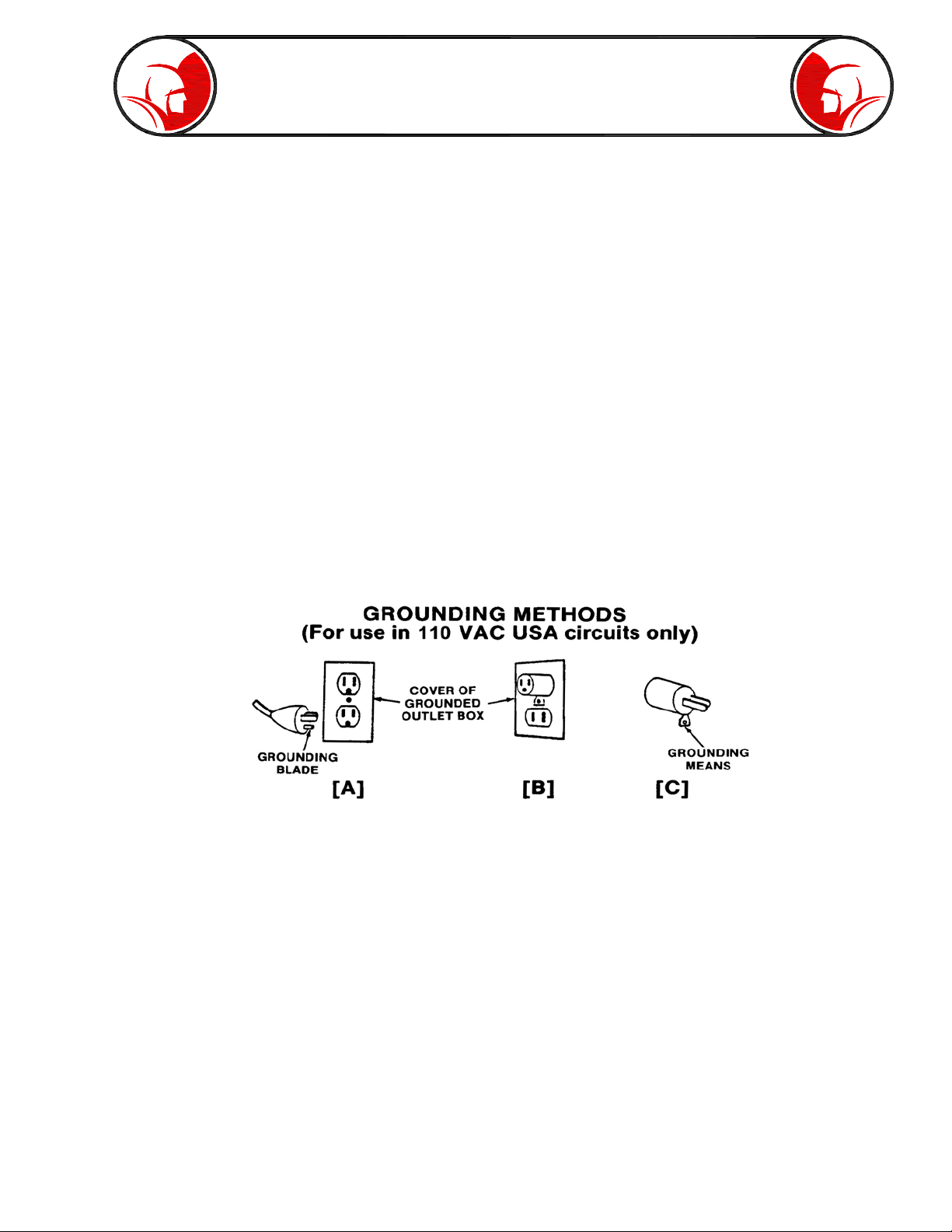
This tool should be grounded while in use to protect the operator from electric shock. The tool is
equipped with a three-conductor cored and proper grounding type receptacle. The green (or
green and yellow) conductor in the cord is the grounding wire. Never connect this wire to a live
terminal. Units designed for use on less than 150 volts, have a plug that looks like that shown in
Fig. 1A. An adapter, (Fig. 1B and 1C), is available for connecting three-prong plugs to two-prong
receptacles, (except in Canada). If such an adapter is used, the green colored rigid ear, lug, or
the like, extending from the adapter must be connected to a permanent ground such as a properly
grounded outlet box.
Figure 1
This machine is equipped with a Ground Fault Circuit Interrupter (GFCI), which should always be
plugged directly into an inspected, grounded receptacle. Plug the three-pronged plug on the
machine power cord with GFCI directly into an inspected grounded outlet and then test and reset
the GFCI.
Never cut off the grounding prong on the power cord for use in a two-hole outlet. Doing so cuts off
your protection from shock. Replace or repair all damaged power cords and components.
Page 5

Safety Instructions (cont.)
3. Extension Cords. DANGER- Improper use of an extension cord will cause death or severe injury.
The GFCI on the machine’s power cord does not protect the operator from electrical shock along
the extension cord.
If an extension cord must be used, it must be of an approved, three-wire construction, equipped
with a three-pronged plug, and in good condition. Replace or repair damaged cords.
Do not use an undersized extension cord. An undersized cord will cause a drop in line voltage
resulting in loss of power and overheating. Use the following minimum gages depending upon
the length of the extension cord:
-16 Ga. –for cords of less than 100 feet in length
-14 Ga. –for cords of 100 feet to 150 feet in length.
If in doubt, use the next heavier gage. (The smaller the gage number, the heavier the cord.) When
the machine is used outdoors, use only extension cords intended for use outdoors and so marked.
Do not allow an extension cord to be exposed to water.
Don’t assume that all three hole outlets are properly installed. Check the outlet and also the adapter,
if used, with an outlet testing device which quickly indicates if a ground is connected. Correct a faulty
test indication before proceeding.
4. Don’t Abuse Cord. Never move or lift tool by cord or yank it to disconnect from receptacle. Keep
cord from heat, oil and sharp edges.
5. Disconnect Power Cord. When not in use, before servicing, and when changing accessories,
such as blades and cutters.
6. Guard Against Electric Shock. Prevent body contact with grounded surfaces such as pipes,
radiators, ranges, refrigerator enclosures.
7. Avoid Accidental Starting. Don’t move plugged-in tools. Make sure switch is in OFF position
before plugging in power cord.
8. Stay Alert. Watch what you are doing. Use common sense. Do not operate tool when you are
tired.
9. Keep Work Area Clean. Cluttered areas invite injuries.
10. Consider Work Area Environment. Don’t expose power tools to rain. Keep work area well lit.
Do not use tool in presence of flammable liquids or gases.
Avoid operating the machine in areas of standing water.
Page 6

Safety Instructions (cont.)
11. Dress properly. Do not wear loose clothing or jewelry. They can be caught in moving parts.
Wear protective hair covering to contain long hair.
Wear standard equipment. (Spartan riveted gloves). Never grasp a rotating cable with a cloth or
loose fitting glove which would get wrapped around cable. Replace gloves if rivets or staples
start to pull out.
Wear rubber boots and wear rubber gloves inside your Spartan cable handling gloves to further
insulate yourself.
12. Use Safety Glasses. Guard against foreign material that might fly off cable.
13. Don’t Overreach. Keep proper footing and balance at all times.
14. Keep Children Away. Do not let visitors contact tool or extension cord.
All visitors should be kept away from work area.
15. Use Recommended Equipment and Accessories.
Use of improper equipment may be hazardous.
Don’t force small cable with attachment to do the job of heavy-duty cable.
16. Don’t Force Tool.
It will do the job better and safer at the rate for which it was intended.
17. Remove Punches and Wrenches. Form a habit of checking to see that punches and adjusting
wrenches are removed from tool before turning it on.
18. Keep Guards in Place. Never operate machine with guard removed.
19. Avoid Operating Machine in Reverse. Operating machine in reverse can result in cable damage
and is used only to back tool away from an obstruction.
Warning! Continued drum rotation in reverse position will cause cable to “jump” out of drum. Possible
operator injury could result.
20. Do Not Over Torque Cables. Excessive and/or continued rotation of the drum once an obstruction
has been encountered will over torque the cable. Kinking or breakage of cable may result. A
worn cable can be identified as being very limber, kinked or as having flattened coils on the
outside of cable. Worn cable should be replaced as soon as possible.
Page 7

Safety Instructions (cont.)
21. Maintain Tools with Care. Keep tools sharp and clean for better and safer performance.
Follow instructions for lubricating and changing accessories.
Never use damaged power cords.
Inspect tool cords periodically and if damaged, repair with proper Spartan replacement parts.
Inspect extension cords periodically and replace if damaged.
Keep handles dry, clean, and free from oil and grease.
22. Check Damaged Parts. Before further use of the tool, a guard or other part that is damaged
should be carefully checked to determine that it will operate properly and perform its intended
function. Check for alignment of moving parts, binding of moving parts, breakage of parts,
mounting and any other conditions that may affect its operation. A guard or other part that is
damaged should be properly repaired or replaced.
Replace defective switches with proper Spartan replacement parts.
Do not use tool if switch does not turn on and off.
23. Store Idle Tools. When not in use, tools should be stored in a dry and locked up place, away from
children.
24. Handling Cables. Be very careful when cleaning drains exposed to cleaning compounds. Wear
protective gloves when handling cable, and avoid direct contact of skin and especially the eyes
and facial areas as serious burns can result from some drain cleaning compounds.
Page 8
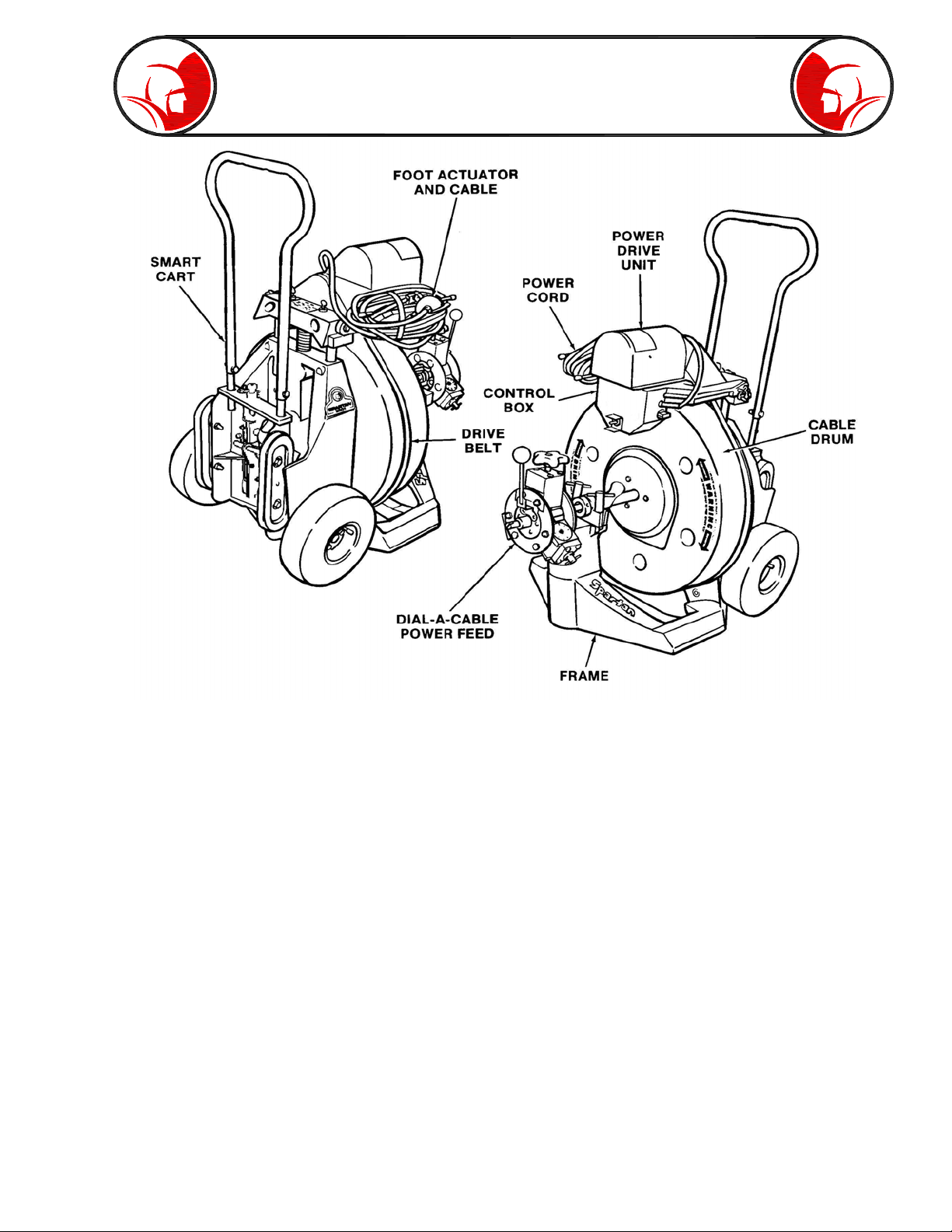
Description
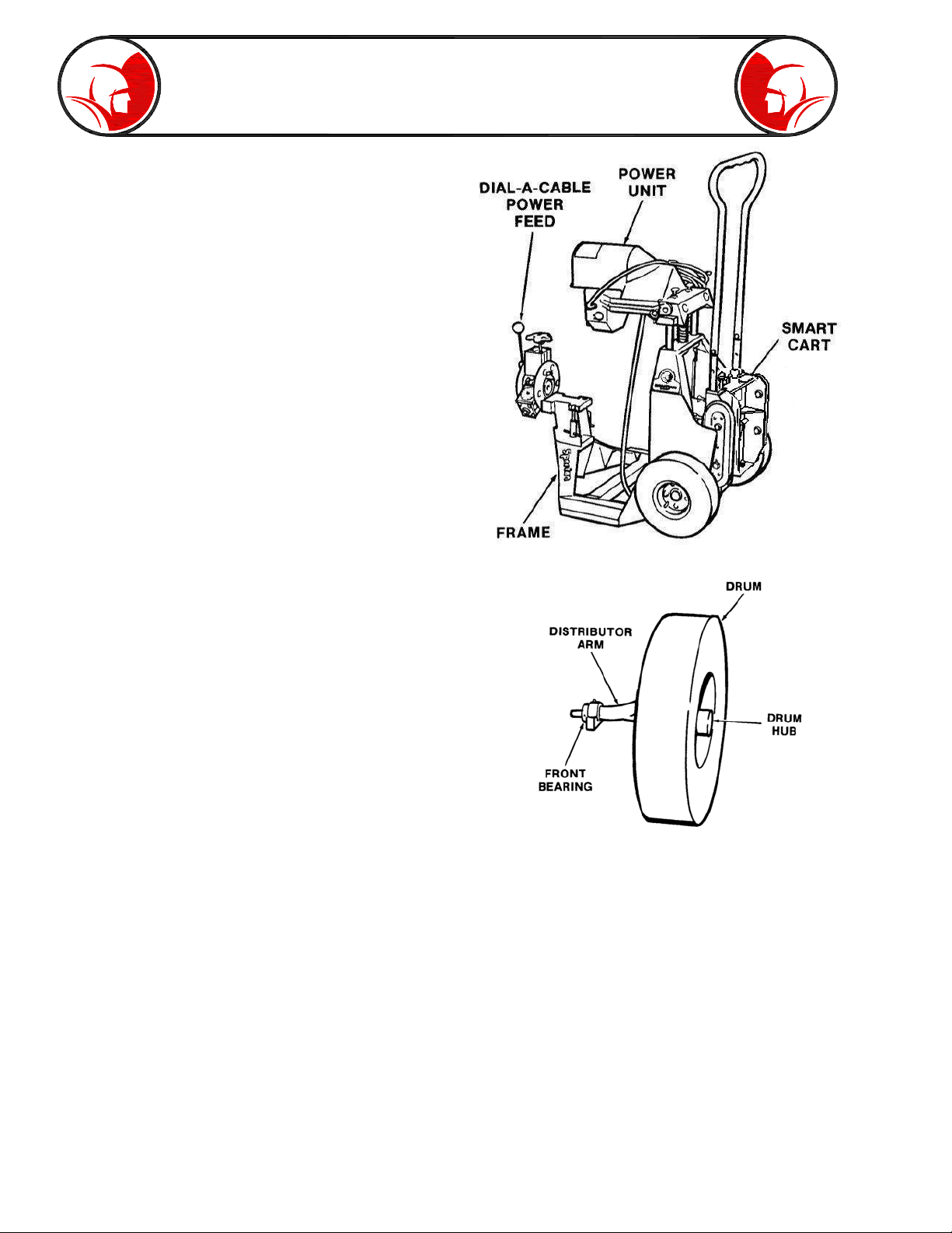
GENERAL DESCRIPTION. The Spartan Model 2001 Electric Sewer and Drain Cleaner is designed
for cleaning 3” to 10” sewer and drain lines up to 300’ long. The complete machine has five major
components - the frame, cable drum, power drive unit with electric controls, “Dial-A-Cable” power
feed, and removable smart-cart.
IMPORTANT FEATURES. The modular design of the Spartan 2001 has many important features
to make it easier to use and more efficient on the job. Handling the power unit and fully loaded drums
separately with the smart-cart makes it easier to transport the equipment close to the point of
operations. This system also makes it easy to quickly change drums with different cable sizes, or for
additional cable on an extended cleaning situation.
The “Dial-A-Cable” power feed gives the operator constant control over cable movement without the
physical labor of pushing the cable ahead. In difficult situations, the operator can slow or reverse the
cable movement.
The Spartan power drive motor senses the need for power when encountering a difficult blockage.
As more torque is required, the motor automatically increases amperage to deliver increased power.
An automatic brake on the motor stops rotation when the foot actuator disconnects the power.
Page 9
Description (cont.)
SPECIFICATIONS
Drum Capacity ..................................... 3/4 inch 112 ft
.66 magnum 137 ft
Cleaning Capacity ...................... 3” to 10” up to 300 ft
Motor ... Permanent Magnet 120VAC 60Hz (Rectified)
4.2 amp (DC) max @ 200 inch - 02 Torque
180 RPM .36 HP 3000RPM @ 1 amp
no load automatic brake
Weight ............. (Mach/drum/cart /anchor cable) 129lbs
Height ..................... Adjustable to 43” to top of handle
Width ............................................... 22 1/2” - 22 3/4”
Length ................................................................... 34”
Drum Speed ............................ 220 RPM with no load
Cable Feed ......... Spartan “Dial-A-Cable” power feed
Frame ...... Extra strength aluminum/magnesium castings
Power Cord ....................... Permanently attached 25 ft
w/ground fault unit
Cable Safety Guide ................................................42”
POWER UNIT. Extra strength aluminum magnesium cast frame forms the base of the power unit.
The cable drum is supported on the frame by the distributor shaft bearing at the front and drum shaft
at the rear. The frame also supports the power cable feed assembly. The electric power unit support
at the top of the frame is spring loaded to maintain drum drive belt tension. The smart cart is attached
to the frame by a shaft inserted in the rear and held in place by the spring-loaded latch assembly.
DRUM ASSEMBLY. The drum which rotates on a shaft on the rear casting of the machine, incorporates
an integral distributor arm and front bearing. The advantage of this drum design is it can be quickly
removed from the frame and replaced by another drum loaded with additional cable or a different
size cable. The drum will accommodate two types of cable systems in a wide range of lengths. An
anchor cable is included with the drum.
Page 10

Description (cont.)
POWER DRIVE ASSEMBLY. The power unit is a totally enclosed, heavy-duty permanent magnet
.36 HP motor with watertight switch and an automatic brake. The motor is mounted on a motor
support assembly which encloses an air-actuated “ON/OFF” switch and “FORWARD-OFFREVERSE” switch. The unique arrangement of the motor support maintains the belt drive tension,
but quickly swings away for drum removal. The air-operated foot actuator, with hose attached, keeps
both operator’s hands free during operation.
CONTROLS AND INDICATORS. The electric motor controls are located in the control box below
the motor. A three position switch on the front of the control box sets the motor at “FORWARD-OFFREVERSE”. The air operated foot actuator is the master “ON/OFF” switch to control the motor
during cleaning operations.
CABLE SAFETY GUIDE. A cable safety guide is
included with the machine. The cable is fed through this
guide which attaches to the Dial-A-Cable feed unit and
extends to the entry point of the drain to protect the
operator from possible cable buckling.
CABLE ASSEMBLIES. The Model 2001 is designed to handle four types of cable assemblies
listed in the Specifications Section of this manual.
POWER CABLE FEED. The Spartan Dial-A-Cable power feed is standard on the Model 2001.
This single-lever control can be operated at an infinite number of speeds from 0 to 30’ per minute to
give the operator constant control over cable penetration. The operator can slow down or reverse
the direction of cable progress quickly with the power feed lever in response to reduced motor
speed which indicates increasing torque.
Page 11
Description (cont.)
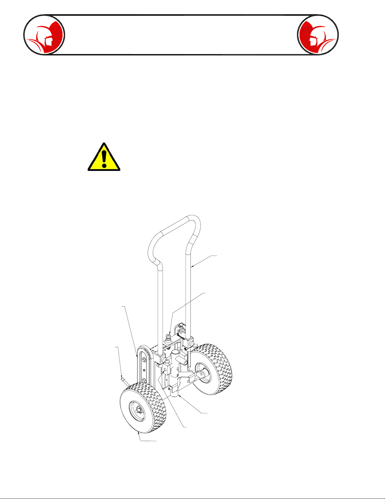
SMART CART. An exclusive feature of the Model 2001 is the Smart Cart
which can transport the complete machine or can be removed to handle
loaded cable drums separately. A double shaft arrangement on the cart
can be swung to carry the complete machine, or the cable drum, or
power unit separately. The cart is equipped with integral continuous belt
stair skids for easier transporting up and down stairways. A kick-stand at
the bottom of the cart supports it to stand alone.
WARNING: Insure the locking pin with chain located on the back
of the Smart Cart is always locked in position before transporting
the drum, and insure the double shaft spring loaded latch is
engaged in the lower lock position when transporting the machine.
If the locking pin with chain is not in position or the double shaft
spring latch is not engaged, the drum or machine can separate
from the Smart Cart and injury or property damage may result.
STAIR
SKIDS
KICKSTAND
HANDLE
CART LOCK PIN
BELT
DOUBLE SHAFT ASSEMBLY
PIVOT BLOCK
10" PNEUMATIC TIRE
Page 12
Description (cont.)
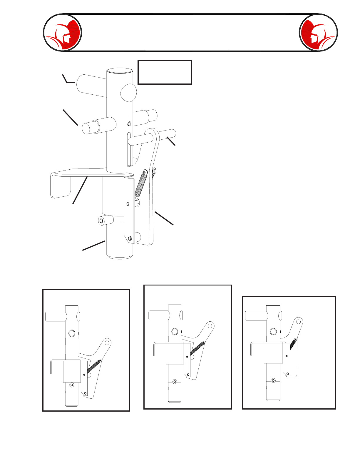
FRAME
SHAFT
PIVOT
SHAFT
LOCKING
ARM
DRUM
SHAFT
Spring latch
engaged in lower
lock position.
SPRING
LOADED
LATCH
HANDLE
SPRING
LOADED
LATCH
DOUBLE SHAFT ASSEMBLY. The
Double Shaft Assembly can be swung
to carry the complete machine, the
cable drum, or power unit separately.
The Assembly has two engagement
positions: upper and lower. The lower
position is used for transporting the
power unit or complete machine by
fastening the locking arm to the frame
cross member. The upper position is
used to remove the smart cart from the
frame, or to stow the locking arm while
using the drum shaft.
Spring latch
disengaged in
lower lock
position.
Spring latch
disengaged in
upper lock
position.
Spring latch
engaged in upper
lock position.
Page 13
Description (cont.)
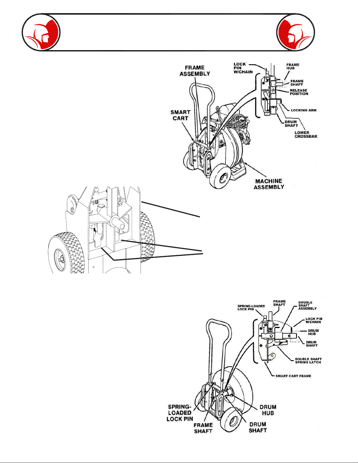
TRANSPORTING COMPLETE MACHINE OR
POWER UNIT. Starting with the Smart Cart
unattached from the Machine/Power Unit, pull
back the spring loaded latch handle to disengage
the spring latch. Slide the spring loaded latch
assembly up and engage the latch in the upper
position. Swing the double shaft assembly so that
the frame shaft portion is horizontal. Move the cart
against the rear of the power unit and push the
frame shaft into the hole in the rear of the casting.
Pull back on spring latch handle to disengage,
then slide assembly down to fasten the locking
arm to the lower crossbar. Confirm spring latch
engages in the lower locked position. To
disconnect the cart, disengage spring latch, slide
assembly up from lower crossbar, and pull the
cart back.
Frame Assembly
Locking arm fastened to frame cross
member.
Note: In order to properly fit individual machines, replacement Double Shaft Assemblies are shipped
without locking pin holes. These holes must be drilled during assembly.
TRANSPORTING A CABLE DRUM. Starting with
the Smart Cart unattached, pull the spring loaded
latch handle back to disenage the spring latch.
Move the assembly to the upper position and
engage the spring latch to hold this position.
Swing the drum shaft portion of the double shaft
assembly into horizontal position on the cart and
lock it in place with the spring loaded lock pin on
the Smart Cart frame. Push the drum shaft into
the rear of the drum hub. Rotate the drum to align
one of the three holes in the drum hub with the
hole in the drum shaft and insert the shaft lock pin
to secure the drum to the cart. To disconnect the
cart, remove the lock pin and pull the cart back.
The Smart Cart has a kickstand on the bottom to
support it standing alone.
Page 14

Before Operation
WARNING: Operator must be thoroughly familiar with the Safety Instructions of
this manual before attempting to operate this equipment.
PREPLANNING OPERATIONS. Before starting a cleaning operation, preplanning will save time,
money and effort. After analyzing the blockage problem; consider the type of cable and tools needed,
determine best location for the machine and cable entry, and consider access to the power source.
CABLE AND TOOL SELECTION. Spartan offers a wide variety of cables and tools to meet sewer
and drain blockage problems. Consult your Spartan Representative to select the cable and tool
combination to work most efficiently on each job. To load or reload drums, and to install tools, refer to
the CABLE AND TOOLS section of this manual.
WORKSITE LOCATION. Check access for machine transportation to the work site. If difficult
stairways are involved, it may be necessary to remove the loaded drum from the machine to transport
the drum and power unit separately with the Smart Cart. For unusual locations, refer to the SPECIAL
APPLICATIONS section of this manual. Plan to place the machine close enough to the entry position
so the cable will be covered by the cable safety guide between the machine and the entry point.
Locate a minimum 15-ampere electrical power source, 115V AC within reach of the 25’ power cord
with the ground fault unit.
TRANSPORTING THE MACHINE. The machine, complete with loaded cable drum, can readily be
transported by the two-wheeled cart. However, when necessary to pull up or down stairways, or load/
unload from a vehicle, the loaded drum can be removed and transported separately. The power unit
and the drum unit should be separated prior to loading/unloading to lower the risk of injury. If needed,
a hoist bracket (see page 45) can be purchased to aid in lifting the machine in and out of a vehicle.
The procedure for removing and replacing the drum is described in the following pages of this manual.
OPTIONAL HOIST LIFT BRACKET. An optional bracket is available that can be attached to the
frame which provides a convienent method for lifting. See page 42 for more information.
Page 15

Before Operation (cont.)
CABLE DRUM REPLACEMENT. Loaded cable drums can be quickly installed on the machine for
added cable reach or to change cable size. Loaded or empty drums can also be removed from the
power unit for replacement or for easier transport of machine and drum.
NOTE: If the drum is loaded with cable, use the Smart Cart to transport it to the power unit. If the
drum is not loaded with cable, it can be transported without the cart.
WARNING: Disconnect electric power cord from power source before removing
or installing any components, making adjustments or working on the machine.
Unintentional start-up could cause personal injury.
CAUTION: Motor brake is on at all times unless machine is plugged into power
and foot actuator is pressed. Pressing the foot actuator will disengage the brake.
The drum action will depend on the position of the 3-position power switch. At
“FORWARD”, the drum will rotate counterclockwise. At “OFF” the drum is free
to rotate by hand. At “REVERSE”, the drum will rotate clockwise. When
necessary to feed or retrieve cable by hand, set the switch at “OFF” and hold
the foot actuator down.
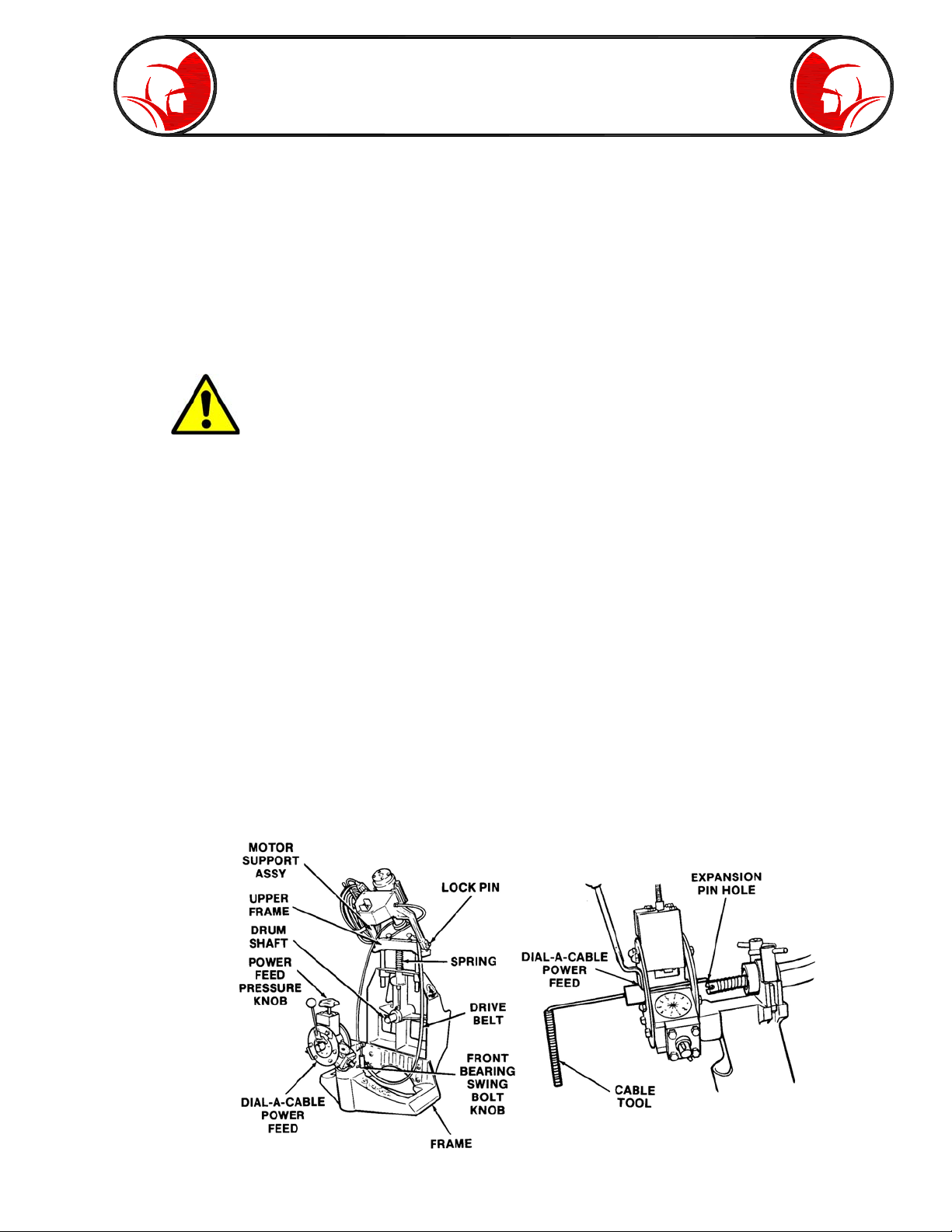
DRUM REMOVAL. Remove the drum from the power unit as follows:
1. Disconnect the cable coupling at the end of the cable loaded in the drum or the drum anchor
cable. Remove the expansion pin completely from the female coupling.
2. Loosen the top power unit knob counter-clockwise the release bearing pressure on the cable.
3. Push the cable through the power feed until it clears the rear of the feed but the female coupling
remains clear of the distributor arm.
4. Remove the black plastic shroud covering the motor and pulley by grasping firmly with both
hands and pulling upward. A metal clasp holds the motor shroud firmly in place. Place the
motor shroud safely aside.
5. Move to the left side of the machine. Place one hand on the top of the spring loaded motor
support assembly (above “CAUTION” decal) and press down firmly. Slide the belt off the side
of drum with the other hand.
6. Remove the lock pin in the side of the motor support. Lift the front of the motor support assembly
until it pivots against the cart handle. Avoid the pinch area. Place the lock pin into the hold
located in the side of the motor support to hold the motor support in the raised position.
7. Loosen the knobs on the swing bolt assemblies in the front of the drum unit on the upper front
casting, until the swing bolts are free to fall to the sides.
8. Push the drum and distributor shaft forward to clear the drum shaft on the rear casting. Roll
Page 16
Before Operation (cont.)
DRUM INSTALLATION. Install the drum on the power unit as follows:
1. Check the drum anchor cable or supply cable extends a few inches from the ditributor arm so
the female coupling is clear. If there is an expansion pin in the female coupling, drive it out
before installing the drum.
2. Position the drum next to the left side of the machine frame with the distributor shaft forward
and the hub towards the rear.
3. The safety cover on the motor is attached by a spring clamp. Lift the cover off from the unit.
Remove the lock pin in the side of the motor support. Swing the support up and reset the lock
pin to hold it there.
CAUTION: Avoid the pinch point between the motor and frame.
4. Locate the drum drive belt, hand it over the drive pulley and place it in the frame so it will be in
position behind the drum when the drum is rolled in place. Roll the drum over the edge of the
frame casting into position on the frame crossbar.
5. Align the drum rear hub with the rear drum shaft on the frame, and push the drum part way
onto the shaft. Allow room for the belt at the rear of the drum. The front bearing should align
with the bearing support at the front.
6. Remove the lock pin and lower the motor support assembly. Reinsert the lock pin. Be sure the
drive belt remains on the drive pulley.
7. To attach the drive belt, push the motor support down against spring pressure above the
CAUTION decal and slide the drive belt over the drum. When the motor is run, the belt will
align itself around the pulley and drum.
8. Push drum tight to rear bearing. Raise the front bearing locks into the lock position and tighten
them securely.
9. Replace the safety cover over the power unit. Press down until the clasp locks in place.
10. Insert the special cable tool through the Dial-A-Cable power feed unit into the expansion pin
hole in the female coupler on the drum cable and pull it through the power feed unit about 3”
beyond the front hub.
Page 17
Before Operation (cont.)
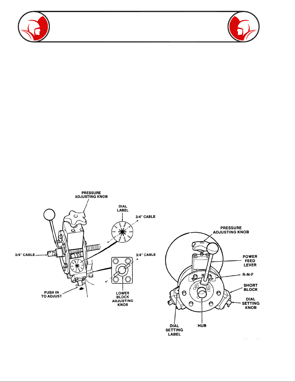
DIAL-A-CABLE POWER CABLE FEED. The Spartan Dial-A-Cable power feed unit provides
infinitely variable cable penetration speeds. The single lever control varies the speed, and the forward
or reverse movement of the cable through two lower and one upper bearing assemblies. The two
lower bearing blocks can be adjusted to match the cable size in the drum. The pressure on the upper
bearing block is adjusted by turning the adjusting knob to the right with just enough pressure to keep
the cable moving. It should be set so that the cable feeds freely in-and-out of the drum.
DIAL CABLE SIZE. To adjust the cable size, first turn the pressure knob counterclockwise to raise
the upper bearing block to clear the cable size. The dial the two lower bearing blocks to match the
size cable in the drum. For example, for 3/4” cable, push each lower bearing knob in and turn it so the
pin in the top is parallel to the 3/4” indicators on the dial. Then release it to be sure it is locked in
position. Be sure both bearing blocks are set at the same cable size. After the cable is pulled through
the unit,the upper bearing knob will be adjusted as necessary for the cleaning operation.
NOTE: When the 3-position motor switch is at “REVERSE” and the drum is rotating clockwise in
reverse, the Power Feed Lever works opposite to the decal “R-N-F” positions. “R” now will feed the
cable forward, and “F” will feed it in reverse.
Page 18

Operation
WARNING: Operator must be thoroughly familiar with the Safety Instructions
section before attempting to operate this equipment.
WARNING: Always use safety goggles. Guard against foreign material that might
fly off the cable.
BEFORE OPERATING CHECK LIST. Before starting operation, check the following:
1. The machine is placed so the cable safety guide will extend from the machine to inside the
cleanout entry point. Allow clear working area around the machine for adding cable and changing
cleaning tools.
2. Check machine for properly installed cable drum with front bearing clamps tight and cable
extending through the power feed.
3. Check Dial-A-Cable power feed bearing blocks are both set for the size cable to be used.
4. Place foot actuator in comfortable and accessible position in order to have control of power at
all times.
WARNING: Never wear loose fitting clothing or jewelry when operating this
machine. Always wear Spartan riveted gloves when handling cable.
WARNING: Do not allow power cord or foot actuator hose or power cord velcro
binder to become entangled in any rotating machine parts, that might cause
personal injury or machine damage.
POWER AND GROUNDING CONNECTIONS
DANGER:
Use of any electrical equipment in a wet or damp environment can cause fatal
shock if not properly guarded against by the operator.
Before plugging the power plug into a power source, study the grounding and
power cable instructions carefully in the SAFETY SUMMARY SECTION of this
manual to assure the power source and connections are safe.
Do not plug the power cable into a direct current source, or higher than 115V AC
power source. Severe damage to the machine could result.
Set 3-position power switch in the center position at “OFF”. Plug the power cord into a 15-amp, 115V
AC power source which has been determined to meet all the safety requirements.
Place the power switch in the “F” (forward) position. Check by pressing down on the foot actuator to
make sure that drum rotates in a counterclockwise direction while facing the front side of the drum.
Page 19

Operation (cont.)
WARNING: Avoid operating machine in reverse. Operating machine in reverse can
result in cable damage and is used only to back stuck or imbedded tool out of an
obstruction. Continual drum rotation in reverse position will cause cable to “jump”
out of drum. Possible operator injury could result.
If the power cord is plugged into an extension cord to the power outlet, there is no ground fault
protection from the socket of the extension cord to power socket. The ground fault breaker only
functions from the machine to the breaker.
GROUND FAULT INTERRUPTER. The ground fault breaker built into the power cord is intended
to cut off the power in case of any ground fault. There is a test button and a reset button on the
breaker. To test the breaker, with the cord plugged into the power source, press the test button. The
breaker should open and cut off the power. The indicator light will go off. To reset the breaker, press
the breaker button and power should be restored and the indicator light is illuminated.
CONTROL SETTINGS
1. Set power switch in “FWD” position.
2. Turn power feed control upper bearing knob clockwise until there is slight pressure on the
cable. Set the power feed control lever at “ N”, center position.
3. Press foot actuator to make sure the drum turns in a counterclockwise direction facing the
drum.
4. Screw the spring end of the safety tube counterclockwise over the hub on the power feed. Be
sure it is all the way on against the face of the feed plate.
5. With power switch at “FWD” and power feed lever midway between N and F position on the
feed plate, press the foot actuator. The cable should feed through the cable safety guide.
Slowly tighten the feed knob if necessary. When cable end is about two inches beyond the
end of the guide tube, release the foot actuator and set the power switch to the center “OFF”
position.
6. Install the selected tools on the cable with either the 2’ leader or the double male coupling.
Refer to the CABLE AND TOOLS section of this manual.
Page 20

Operation (cont.)
CLEANING OPERATION. Move the machine as close to the entry point as possible. The end of the
cable safety guide and cutting tool should be inside the entry point of the cleanout.
This machine should be operated from the side of the power feed. During operations, always have
one hand on the power feed lever, and the other hand resting on the cable safety guide so torque
build-up may be felt as the motor slows down. The operator should wear Spartan riveted leather
gloves whenever machine is being operated.
Move the power feed lever to midway point between “N” and “F” on the nameplate on the Dial-ACable feed unit.
Step on foot actuator and slowly tighten (turn clockwise) the power feed knob. When cable is driving
steadily forward, stop turning the knob. Move the power feed lever toward “R” position on the
nameplate. Cable should now retrieve properly.
NOTE: Do not run the cutting tool into the end of the cable safety guide.
Do not continue to tighten the knob any more at this time. If cable slips after running 100’ or more into
sewer or whenever a stoppage is encountered, the knob may be tightened until cable is again moving
steadily. Do not tighten knob any more than is necessary to cause cable to move in a steady motion.
Excessive tightening may damage the cable or feed or overload the motor.
To start the cleaning operation, place one gloved hand on the cable safety guide about 18” from the
power feed. Keep the other hand on the power feed lever, while stepping on the foot actuator to start
the drum rotating.
WARNING: Make sure to keep downward pressure on the safety guide tube at all
times since flexible cable is subject to buckling under high torque conditions.
Control forward movement of the cable by moving the feed control lever towards the “F” (forward)
position.
Never try to force the cable into the line. Choose a proper feeding speed that gives a smooth cutting
action until the cable reaches resistance and torque builds up, then slow down or stop and take
clearing action.
The design of the motor is such that as soon as the blade end of the cable gets hung up in an
obstruction, a reduction in speed and a decrease in motor sound level provide notice to the operator
to pull the blade away from the obstruction, thereby releasing the tension that has been built up in the
coil-spring cable. That release of tension reduces the chances of buckling, kinking or breakage of
the cable.
WARNING: Do not permit blade end to get hung up in an obstruction for more
than 2 to 3 seconds. It is important to keep the cable rotating. Remember, do not
operate the machine to the point where the cable begins to buckle. This practice
is dangerous and could damage the cable.
Page 21

Operation (cont.)
Kinkage and breakage of cable are caused by allowing the working end of the cable to get hung up
in an obstruction while twisting the other end with the motor, until something must give. The only way
to clean an obstruction from a line, or negotiate a bend in a line, is with the blade rotating.
A good rule to follow for releasing tension on a cable is: when the blade gets hung up in the obstruction
and fails to rotate, a motor RPM sound reduction will be noticeable, which indicates it is time to pull
the blade away from the obstruction. As the cable is pulled away, all tension in the cable will be
released immediately and the blade will turn at high speed.
As soon as the blade is free, push it back into the obstruction quickly to utilize the built-up power of
the spinning cable which enables cleaning the line more quickly and efficiently. This propeller type
action helps the blade cut or tear through the obstruction.
WARNING: Do not allow tool to get hung up in an obstruction. But, if a tool does
get hung up in an obstruction, a reverse feature is provided on this machine for
just this purpose. Do not reverse machine until motor and drum come to a
complete stop. Avoid operating this machine in reverse for any other purpose.
In the event the blade does get hung up on an obstruction and cannot be released by backing off with
the power drive lever, move the power switch to the “OFF” position, and permit the machine to come
to a complete stop. The brake on the motor will stop rotation as soon as the foot actuator is released.
Then, move the toggle switch to the “R” position.
Now start the machine slowly. By depressing and releasing the foot actuator rapidly until the drum
rotates at leaset one revolution, see if the blade can be removed from root or other obstruction by
this reverse action.
When blade is released, let the machine come to a complete stop again. Then place the toggle
switch in the “F” position. Make sure that drum rotates counterclockwise, when standing in front of
machine, except when reversing it to free cutting tool from obstruction.
After cutting through one group of roots, it is a good practice to pull back the cable, remove the
debris from the blade and reenter the pipe to take another cut. This final cut gives a thorough cleaning
job.
Sometimes a stoppage can be relieved by setting the power feed lever straight up where the drive is
in neutral position. there is no lateral movement of cable at this point. This enables positioning the
blade against the stoppage and chewing it away if necessary.
MAIN SEWER OR SEPTIC TANK OVERRUN. It is very important to know the approximate distance
from inlet to main sewer or septic tank. Overrunning cable into main sewer or septic tank can allow
cable to knot up and prevent its retrieval.
Page 22
 Loading...