

Sparta AS-30B Technical Manual
SPARTA
AS-3OB
AUDIO
TECHNICAL
CONSOLE
MANUAL
AS-30B
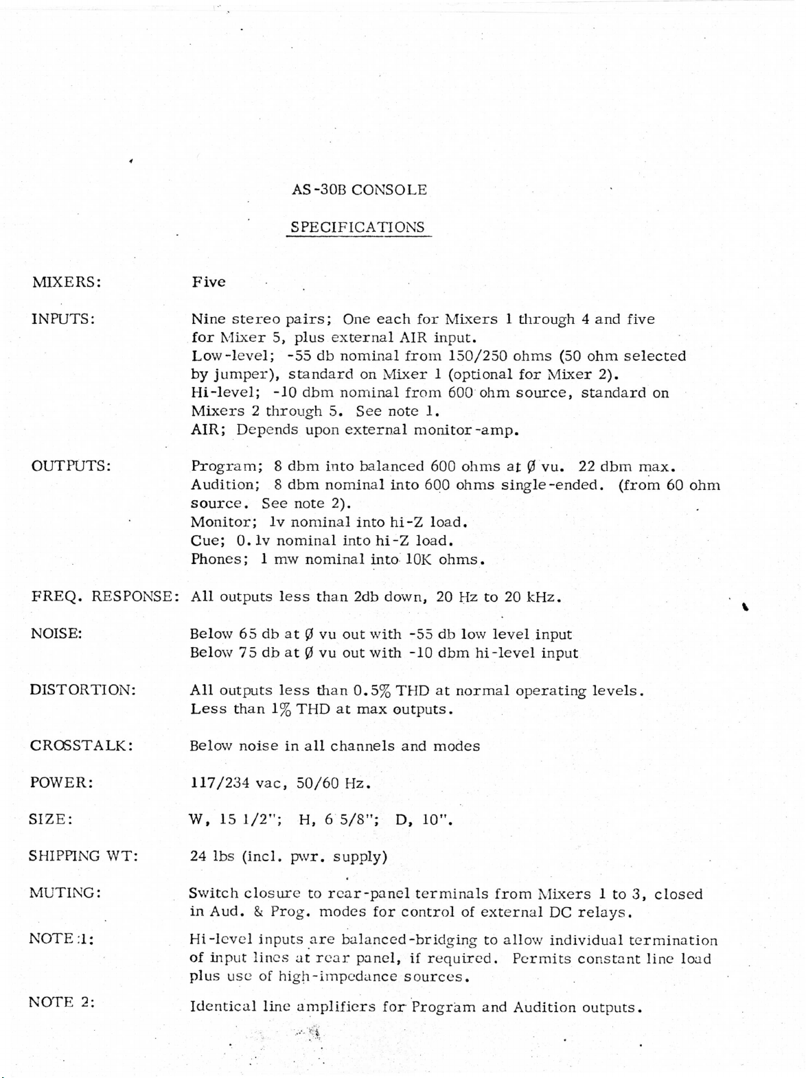
CONSOLE
SPECIFICATIONS
MIXERS:
INPUTS:
OUTPUTS:
FREQ.
RESPONSE:
NOISE:
Five
Nine
stereo
for
Mixer
Low-level;
by
jumper),
Hi-level;
pairs;
5,
plus
-55
standard
-10
dbm
Mixers 2 through
AIR;
Program;
Depends
8
dbm
upon
Audition; 8 dbm
source.
Monitor;
Cue;
Phones; 1 mw
All
outputs
Below
Below
0.
65
75
See
Iv
lv
nominal
less
db
at 0 vu
db
at 0 vu
note
nominal
nominal
One
each
for
Mixers 1 through 4 and
external
db
nominal
nominal
5.
See
AIR
input.
from
on
Mixer 1 (optional
from
note
1.
external monitor-amp.
into
nominal
into
into
than
2db
out
out
balanced
hi-Z
into
down,
with
with
into
hi-Z
10K
-55
-10
600
600
load.
load.
ohms.
20
db
dbm
150/250
600
ohm
ohms
ohms
Hz
to
low
level
hi-level
ohms
source,
at 0 vu.
for
(50
Mixer
standard
22
single-ended,
20
kHz.
input
input
ohm
2).
dbm
five
selected
on
max.
(from
60
ohm
DISTORTION:
CROSSTALK:
POWER:
SIZE:
SHIPPING
WT:
MUTING:
NOTE
NOTE
;1:
2:
All
outputs
Less
Below
117/234
W,
24
Switch
in
Hi-level
of
plus
than
noise
vac,
15
1/2";
lbs
(incl.
closure
Aud. & Prog,
inputs
input
use
lines
of
Identical
less
than
1%THD
in
all
50/60
at
channels
Hz.
H, 6 5/8";
pwr.
supply)
to
rear-panel
modes
are
balanced-bridging
at
rear
high-impedance
line
amplifiers
0.5%
max
for
panel,
THD
outputs.
and
D,
10".
terminals
control
if
sources.
for
Program
at
normal
modes
of
external
required.
and
from
to
allow
operating
Mixers 1 to
DC
individual
Permits
Audition
levels.
relays.
termination
constant
outputs.
3,
line
closed
load
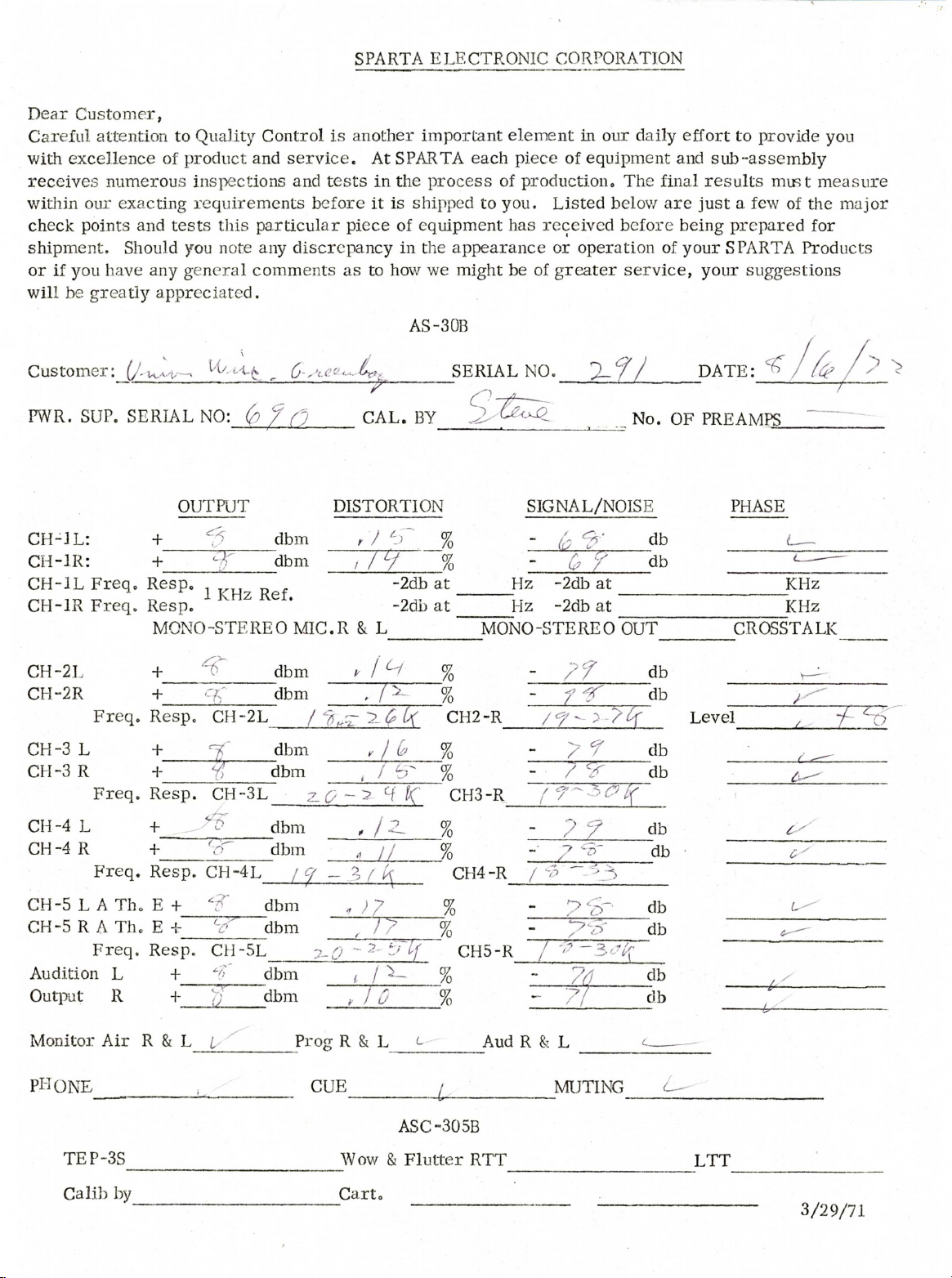
Dear
Customer,
Careful
with
excellence
receives
within
check
our
points
shipment.
or
if
you
will
be
greatly
attention
numerous
exacting
and
Should
have
any
to
Quality
of
product
inspections
requirements
tests
this
you
note
general
appreciated.
Control
and
service.
and
before
particular
any
discrepancy
comments
SPARTA
is
another
tests
piece
as
At
SPARTA
in
the
it
is
of
in
to
how
ELECTRONIC
important
each
process
shipped
to
equipment
the
appearance
we
might
AS-3
OB
element
piece
of
production.
you.
has
Listed
received
or
be
of
greater
CORPORATION
in
our
daily
of
equipment
The
below
before
operation
and
final
are
being
of
service,
effort
to
sub-assembly
results
just a few
prepared
your
SPARTA
your
suggestions
provide
must
of
Products
you
measure
the
major
for
Customer
PWR.
SUP.
CH-1L:
CH-1R:
CH-1L
Freq.
CH-IR
CH-2L
CH-2R
CH-3
L
CH-3 R
CH-4
L
CH-4R
Freq.
Freq.
Freq.
Freq.
\
SERIAL
NO:
OUTPUT
+
^dbm
+
Resp.
Resp.
MONO-STEREO
+
^
+
Resp.
9,~
CH-2L
+
+
Resp.
+
%
CH-3L
-
+
Resp.
CH-4L
(p
~dbm
/
dbm
dbm
dbm
dbm
dbm
dbm
r
CAL.
DISTORTION
r / b
, / y
MIC.R & L
*
/
, / >-•
/
,
,
z'.Q ~
_
2 cf
,
/
A
If
— % \
-2db
-2dfa
JL
/
Z.
BY
K
SERIAL
at
at
~
%
CH2~R
CH2-R
%
%
CH3-R
%
%
CH4-R
NO.
2-f/
SIGNAL/NOISE
£
/
Hz
-2db
at
Hz
-2db
at
MONO-STEREO
/f
"
nr
/bf
f
-
/
y
?
?
7
/
<2
No<
OUT
~db
v
f
db
db
db
db
db
db
db
db
db
DATE:
PREAMPS
0F
"
Level
PHASE
<
KHz
KHz
CROSSTALK
%
f
^
/^
%
"
?
CH-5 L A
CH-5 R A
Freq.
Audition
Output
Monitor
Pl"I
ONE
TEP-3S
Calib
Th. E +
Th. E -t-
Resp.
L
R
Air R &
by
+
+
yjdbm
L
f
V"
CH-5L
"f>dbm
u
dbm
dbm
Prog R &
,
)•?
y^Q
-^.71
f
t
/
L
CUE
Wow & Flutter
Cart.
%
%
%
f
CH5-R
%
%
^
ASC-305B
RTT
-
/
Aud R &
9~-
&
7/
L
MUTING
db
db
db
db
db
db
^
Q
LTT
3/29/71
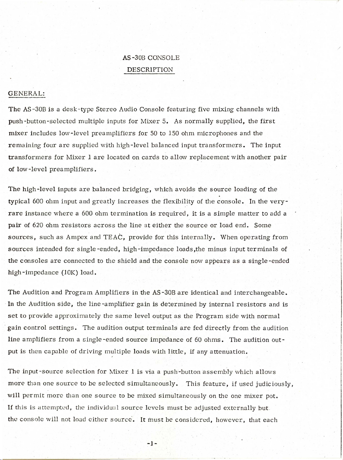
GENERAL:
The
AS-30B
is a desk-type
Stereo
AS-3OB
DESCRIPTION
Audio
CONSOLE
Console
featuring
five
mixing
channels
with
push-button-selected
mixer
remaining
transformers
of
The
typical
rare
pair
sources,
sources
the
high-impedance
includes
low-level
high-level
600
instance
of
620
such
intended
consoles
low-level
four
are
for
Mixer 1 are
preamplifiers.
inputs
ohm
input
where a 600
ohm
resistors
as
Ampex
for
are
connected
(10K)
multiple
preamplifiers
supplied
are
and
single-ended,
load.
with
balanced
greatly
ohm
across
and
TEAC,
to
inputs
located
termination
the
for
high-level
on
bridging,
increases
the
line
provide
high-impedance
shield
Mixer
for
50
balanced
cards
is
at
and
5.
to
150
to
which
the
flexibility
required,
either
for
this
the
console
As
normally
ohm
input
allow
avoids
the
source
internally.
loads,the
supplied,
microphones
transformers.
replacement
the
source
of
the
console.
it
is a simple
or
load
When
minus
now
appears
the
first
and
the
The
input
with
another
loading
In
matter
end.
input
as a single-ended
Some
operating
terminals
of
the
to
pair
the
very-
add
from
a
of
The
Audition
In
the
set
to
gain
control
line
amplifiers
put
is
The
input-source
more
will
If
the
than
permit
this
console
Audition
provide
settings.
then
capable
one
more
is
attempted,
will
and
Program
side,
approximately
from a
source
the
of
driving
selection
to
tiian
one
the
not
load
The
single-ended
individual
Amplifiers
line-amplifier
the
same
audition
for
be
selected
source
either
multiple
output
source
Mixer 1 is
to
source
source.
in
the
AS-30B
gain
is
determined
level
loads
simultaneously.
be
output
terminals
impedance
with
little,
via a push-button
mixed
simultaneously
levels must
It
must
be
are
identical
by
as
the
Program
are
fed
of
60
ohms.
if
any
assembly
This
feature,
be
adjusted
considered,
and
internal
side
directly
The
attenuation.
if
on
the
one
externally
however,
interchangeable.
resistors
with
from
the
audition
which
used
mixer pot.
that
and
normal
audition
out-
allows
judiciously,
but
each
is
of
two
if
required.
sources
will
then
be
loaded
by
die
other,
and
suitable
AS-30B
isolation
Description
must
be
(cont'd)
provided,
INSTALLATION:
connectors,
not
required
accommodate
panel
manual
Audio
8737
satisfactory
required
adjacent
simply
connection
"floating".
connections
connections
(stranded)
are
since
several
or
to a numbered
to
since
terminal.
clipping
for
the
This
Input
made
the
are
are
or
8739
use
solid
solid
wire
Single-ended
off
die
cable
prevents
and
Output
via
rear-panel
barrier
stripped
clearly
diagram.
normally
(solid).
wire
is
unused
shield
the
Connections,
barrier
strips
wires
identified
in a permanent
easier
conductor.
and
possibility
made
Either
to
outputs
die
are
per
with
handle
transformer
strips.
designed
terminal,
to
facilitate
twisted-pair,
may
be
installation
and
and
inputs
The
of
setting
with
the
with
either
installation
used,
less
apt
can
input
terminals
input windings
up a severe
exception
Spade
captive
solid
shielded
although
where
to
inadvertently
use
die
of
die
lugs
or
fanning-strips
plates
or
without
it
flexibility
same
include a ground
ground-loop
stranded.
cable
is
generally
type
are
to
easily
resorting
such
ungrounded
Mixer 1 XLR
are
Rear
to
die
as
Belden
more
is
not
short
cable
and
to
by
also
an
or
permits
if
desired.
A
central
master
one
side
In
ground
ground,
like
and
of
the
manner,
lug
as
transformer
die
program
is
provided
heavy a guage
on
input
the
strap
to
line
rear
be
outputs
panel
or
braid
grounded
are
for
as
for
single-ended
also
isolated.
connection
practical
to
the
should
operation
system
be
used.
CIRCUIT DESCRIPTION,
SPARTA
AUDIO
CONSOLES
GENERAL . The
SPARTA
selecting,
methods
signals.
elsewhere
Microphone
level
to
used.
essentially
consoles,
from
0dbm.
In a normal
mixing
used
to
Features
in
the
Preamplifiers.
the
preamp
depending,
the
description
mono
and
amplifying
process
applicable
appropriate
to
of
situation,
same
level
to
follow
or
stereo,and
the
auxilliary
to
specific
manual
With a nominal
the
mixer
course,
on
then,
as
the
is
generally
outlined
usual
program-sources
functions
consoles
sections.
gain
potentiometer
the
sound
the
preamplifier
high-level
the
such
of
level
input
applicable
basic
as
cue
are
then
55db.
is
typically
and
output
signals,
to
all
system
and
of
plus
monitor
the
discussed
the
output
-10
microphone
is
at
resulting
in
approximately
Preamp
referring
As
with
easy
All
gain
to
normally
150/250
conversion
SPARTA
preamplifier
able
with
the
can
be
the
preamplifier
supplied
ohm
to
Audio
in
Consoles
the
high-level
same
changed
mixer-level
to
circuit
by
SPARTA,
microphones.
use
with
30/50
are
first
mixer
input
cards,
settings
accommodate
description.
the'input
A
transformer
ohm
microphones.
supplied
as
position.
however,
for
unusual
transformer
tap
standard
The
preamplifiers
so
additional
normal
is
operation.
situations
is
wired
provided
by
for
for
with a microphone
are
interchange
microphone
use
1.
CIRCUIT
DESCRIPTION,
GENERAL
preamplifiers
level.
High-Level
transformers
the
proper
to
allow
of
setting
input
Mixing
through a high-value
cables.
takes
may
be
Inputs
which
Mixer
single-ended
up
potentiometers.
undesired
place
incorporated,
are
brought
are
suitably
connection
ground-loops
by
feeding
series
to
the
terminated
and
the
resistor
or
alternately,
primaries
The
primaries
also
or
output
(10K
all
of
input-isolation
and
connected
are
floating
to
prevent
common-mode
•
of
or
each
27K)
mixer
to a common
inputs
the
signals
potentiometer
may
directly
(ungrounded)
possibility
via
mixing
be
to
the
high-
bus,
which
to
Since
amp
resistors,
Mixer
the
which
is
have a very
the
becomes a "current
pots.
sum
in
usually
Mixer
which
of
the
turn
located
low
feed
in
The
output
currents
leads
input
resistors
turn
at
to a mixing
with
the
impedance,
are
sink"
is
of
and
determined
the
mixer
its
input.
amplifier.
line
amplifier,
typically
so
much
responds
by
amp,
higher
the
then,
The
100
to
the
voltage
is
mixing
is
specifically
ohms.
in
value,
current
available
proportional
amplifier,
designed
the
mixer
in
the
feed
from
to
the
CIRCUIT
DESCRIFHON.
GENERAL
Mixer
each
mixer
then,
from
There
feed
feed
amp
will
another
is
resistors,
recover
the
program
mixer
about
pots , with
one
isolation
resistor
rather
have
is
excellent
will
follow
than
to
relatively
another
mixer-pot.
obviously a significant
but
the
power
the
loss
in
the
to
substantially
the
mixer
mixer-pots
o'clock.
with
the
little
effect
loss
levels
amplifier.
the
same
this
easiest
Mixer
are
at
their
system
since
path — obviously
pot.
upon
of
level
Changing
the
program
so
low
Mixer
usual
amp.
as
originally
operating
program
power
that
the
current
one
mixer-pot,
level
in
the
it
is a simple
gain
is
fed
positions,
from
into
the
coming
mixer
set
to
to
the
matter
restore
to
Since a "current"
it
allows
critical
the
bulk
Output
essentially
To
test
a
high-level
operating
Master
the
use
of
the
precise
and
cost
of
the
mixer
the
the entire
input,
position
gain
control.
mixer
of
of
system
same
mixer
the
and
operates
high
impedance
source
impedance, there
precision
is
level
as
system, a -10
appropriate
the
signal
from a relatively
mixer-pots.
ladder
then
the
attenuators.
fed
to
original
the
or
mixer
is
viewed
pot
high
And
is
no
Master
high-level
dbm
signal
is
set
or
measured
source
since
need
gain
program
is
at
the
across
impedance,
it
is
not
to
resort
control
material.
provided
normal
the
to
at
at
3.
CIRCUIT
The
Line
DESCRIPTION,
Amplifier
provides
GENERAL
the
final
amplification
between
the
Master
gain
control
loss
or
isolation
rated
For a rated
must
distortion,
the
4
db,
amplifier
and
of
the
level.
be
considered: A minimum
output
to
prevent
output-impedance
the
line
output
Master
pads,
output
must
transformer
gain
and
of
8dbm
be
available
interaction
terminals.
control,
provide
into a 600
must
be
with
must
compensate
power-gain
ohm
of
10
dbm
to
handle
isolated
line
reactances.
properly
It
must
for
for
line
of
additional
program
from
the
match
therefore
any
losses
driving
at
peaks
line
the
the
zero
with a pad,
Finally,
line
recover
output
VU,
several
gain,
(headroom).
transformer
the
in
matching
line
without
the
line
signal
at
factors
Also,
typically
primary
so
the
output
The
line
transformer
on
program
to
the
line
transformer
This
is
considered
VU
Meter.
appears
as a non-linear
terminals
peaks.
plus
the
and
internal
The
standard
are a true
must
The
power-losses
in
then
line
amplifier
loss
detail
in
VU
meter
impedance
necessary
600
ohm
source
handle a nominal
must
in
the
the
line-amplifier
contains
to
its
be
capable
line
pad,
to
obtain a proper
rectifier
signal
.
level
section
source.
of
insertion
diodes
12dbm,
of
supplying
loss
impedance
of
the
and
To
avoid
and
22dbm
18dbm
in
the
match.
manual.
consequently
introducing
CIRCUIT
DESCRIPTION,
GENERAL
distortion
the
meter
It
is
also
0vu
when
designed
linearity
This
rather
is
the
4
db
of
"H"
pad
latter
than a simple
line
attenuation
on
the
and the
necessary
the
line
as
to
appear
of
the
meter
requirement
transformer
is
not
required
program-line,
line.
to
attenuate
is
at
8dbm
to
the
meter
indication.
accounts
series
in
the
resistor.
output,
meter
since
it
the
and
for
ahead
pad
the
is
necessary
level
finally,
as a 3.9K
the
meter
In
SPARTA
of
the
for
increased
meter
need
to
to
the
the
attenuator
ohm
pad
line
not
provide
meter
source
consoles,
pad,
isolation.
be
so
being a "T"
which
balanced
isolation
it
can
must
to
be
preserve
configuration
the
metering
allows
A
balanced
to
between
indicate
so
the
an
added
ground.
source
Cue.
potentiometer.
through
termainal
cue
provided.
Monitor.
SPARTA
Common
the
level
consoles,
cue
for
control,
Although
to
all
SPARTA
In
the
switches and
feed
to
an
internal
provisions
in
all
consoles
simplest
external
amplifier
cases
case,
isolation
cue
amplifier.
and
for
program-line
the
source
is a "Cue"
program
resistor's,
optional-use
of
program
material
monitoring
position
is
delivered
In
more
material
on
from
each
elaborate
internal
vary
each
is
Mixer
mixer,
to a rear-panel
consoles,
speaker
in
different
the
are
output
a
CIRCUIT
DESCRIPTION,
GENERAL
stage
components
and
of
the
quality,
program
to
follow,
whereas the
line
the
amplifier.
monitor
VU
meter
Since
provides
alone
only
there
constant
indicates
are
no
active
assurance
level.
or
non-linear
of
both
level
\
CIRCUIT
PREAMPLIFIER,
The
1018
rophones
jumper
accommodate
The
1018
The
microphone
and
low
former's
ed
frequency
DESCRIPTION/MAINTENANCE
1018
Preamplifier
and
provides a nominal
is
provided
30/50
Preamplifier
transformer
frequency
80K
secondary
response
is
supplied
on
the
circuit
ohm
microphones.
differs
response.
impedance
and
standard
gain
of
55db
board,
from
its
is a miniaturized
The
1018
to
excellent
either a wire
predecessor,
circuitry
provide
overload
for
operation
into a 600
or a low-value
the
PC-mounting
takes
improved
characteristics.
with
150/250
ohm
or
higher
1008A,
full-advantage
noise
in
several
type
with
performance,
ohm
mic-
load.
resistor,
respects.
extended
of
the
trans-
expand-
A
to
high
With
0
dbm,
event
may
changed
The
amplified a further
passes
The
base
normal
dbm.
which
that
be
added
input
through
emitter
impedance
microphone
The
maximum
assures
microphones
in
series
in
value
signal
of
is
emitter-follower Q3
Q2
of
to
is
input
output
more
lower
amplified
35db
heavily
Q2
must
with
by
is
than
the
quite
levels,
level
adequate
be
used,
the
microphone
preamp
approximately
transistors
bypassed
low,
the
of
the
gain,
to'provide
to
being
output
1018
head-room
which
as
Q1
and
ground
essentially a forward-biased
level
before
provide
or a resistor
described
20db
Q2.
the
by
clipping
in
normal
unusually
by
the
The output
necessary
capacitor
to
the
in
later.
input
mixer
operation.
the
transformer
low
C8;
is
in
high
1018
signal
output
therefore
will
be
excess
output,
may
from
impedance.
diode.
approx-
of
In
the
a
be
and
then
Q2
the
14
pad
then
I.
Most
of
the
signal
current
from
Q1
passes
to
the
base
of
Q2,
then,
rather
than
through
maximum
The
relatively
Q2
maximum
appears
A
portion
the
feed-back
the
emitter
must
therefore
at
emitter
current
high
of
the
of
to
much
of
Q3
compared
voltage
low
the
output
of
Ql.
the
higher
gain
is
cause a significant
impedance
emitter
from
not
gain
signal
Since
impedance
Q1,
although
bypassed,
to
Q2's
from
Qland
of
Ql
collector
Q2,
emitter
determined
Q2
is
in-phase
of
the
however,
signal
and
since
of
Q3
both
collector
the
voltage
so
resistor
voltage
Q3
.
by
feedback
invert
with
the
the
resistor
gain
the:base
R4.
across
is
an
emitter-follower
attenuator
signals
signal
R3.
is
relatively
impedance
The
signal
R4. This
through
input
This
of
current
R8/R9
them,
to
the
assures
small.
Q3
is
from
assures
this
signal
appears
the
base
of
a
at
Ql.
This
consitutes
input
normal
plus
R8
were
by
provide
able
The
effect
signal.
the
or
R9
to
6db,
selection
use
The
closed-loop
ratio
will
be
the
of
of
raising
of
change
increased
since
the
same
of
negative
negative
open-loop
gain
R8
to
output
feed-back
gain
the
feed-back,
is
R9.
the
gain
to
360
of
can
be
feedback
input impedance
since
gain
determined
It
ohms,
the
voltage
(without
can
now
of
the
amplifier
the
amplifier
to
obtained
to
control
to
the
feed-back)
by
the
be
seen
voltage
would
the
emitter
simply
gain
via
Ql.
feed-back
turns-
that
changing
proportionally.
gain
of
only
of
by
selecting
the
This
permits
is
ratio
the
need
Ql.
input
attempts
extremely
of
amplifier
Consequently,
emitter
the
the
the
to
swing
the
to
cancel
high,
input
value
For
value
use
transformer
of
example,
would
half
of
also
has
of a high-ratio
the
so
the
either
if
decrease
as
far
reason-
R9.
the
R9
to
 Loading...