

Sparsh 540 TVL OSD Camera Series, SP-354DO, SP-354DA49O, SP-354CSNO, SP-354CTNO User Manual
...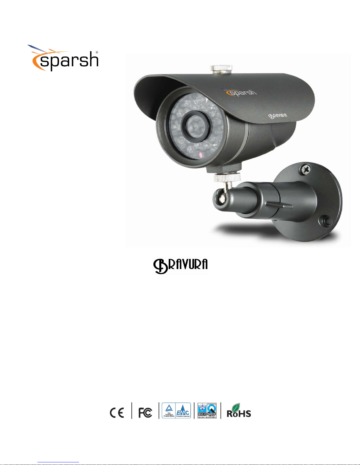
540 TVL OSD Camera Series
User Manual
V1.0

DESCRIPTION
The camera uses SONY charge coupled device (CCD)
image sensor, and employs digital signal processing
(DSP) chip-set for image control, and all integrated
state circuitry which provides extremely long life and
high reliability. This camera offers excellent image
quality, and is not subject to distortions from magnetic
fields. High resistance to shock and vibration, and easy
to install, this camera is the best choice for your CCTV
system.
TRADEMARKS
Optimum operational temperature range is 0°C and
+50°C.
• Do not install under varying light conditions.
Continuously varying light frequency might cause
problems in the normal functioning of the camera.
• Do not put camera under shocks and jerks.
This may cause the serious disorientation or the
distortion in the components thereby causing the
malfunctioning of the product.
• Do not install under excess of humid conditions.
Sparsh logo is registered trademarks of Samriddhi
Automations Pvt. Ltd.
SONY, SONY Super HAD & SONY Super HAD-II is
registered trademark of Sony Incorporation.
All other brand, product names, and service names are
trademarks or registered trademarks of their respective
companies or organizations
LIMITATION OF LIABILITY
• This publication is provided “as is” without warranty of
any kind, either express or implied, including but not
limited to, the implied warranties of merchantability,
fitness for any particular purpose, or non-infringement of
the third party’s right.
• This publication could include technical inacc uracies or
typographical errors. Changes are added to the
information herein, at any time, for the improvements of
the publications and/or the corresponding pr oduct(s).
This may cause the deposition of water droplets on the
lens and several other sensitive components thereby
lowering the picture quality.
• Do not expose the camera directly to high light intensity
pulse.
This may damage the C CD or may create de ad pixels in
the CCD.
• Do not expose camera to water.
This may result in malfunctioning of the camera or may
result in the corrosion of certain components due to
minerals contained in water.
• Do not expose camera to radioactivity.
Radioactive exposure may cause damage to CCD or may
produce dead pixels.
• Do not attempt to open the camera.
Unauthorized opening of camera is not permissible as it
could cause breakage of the fragile components.
WARNINGS & CAUTIONS
• The information provided in the user manual is for the
safety of the customers. Please read the user manual
before operating the product and follow the instructions
provided accordingly.
Warning Messages
• Do not install under excess hot conditions.
• Do not use low quality cables and power supply.
Only recommended cables/wires and power supply
should be used for proper functioning of the camera.
If any abnormality occurs, make sure to unplug the unit
and contact your local dealer or our service centre.
INSTALLATION
•
• Installation must be carried out by the authorized
personals only.
Image directly or strong light
Noise in
Video
Check illumination is low or not
• Check power supply voltage is low or not
• Check proper wire connectivity
• Surface on which the camera is to be mounted must be
strong enough to hold the camera firmly, if not so
reinforce the surface again so that the camera may not
fall off the surface.
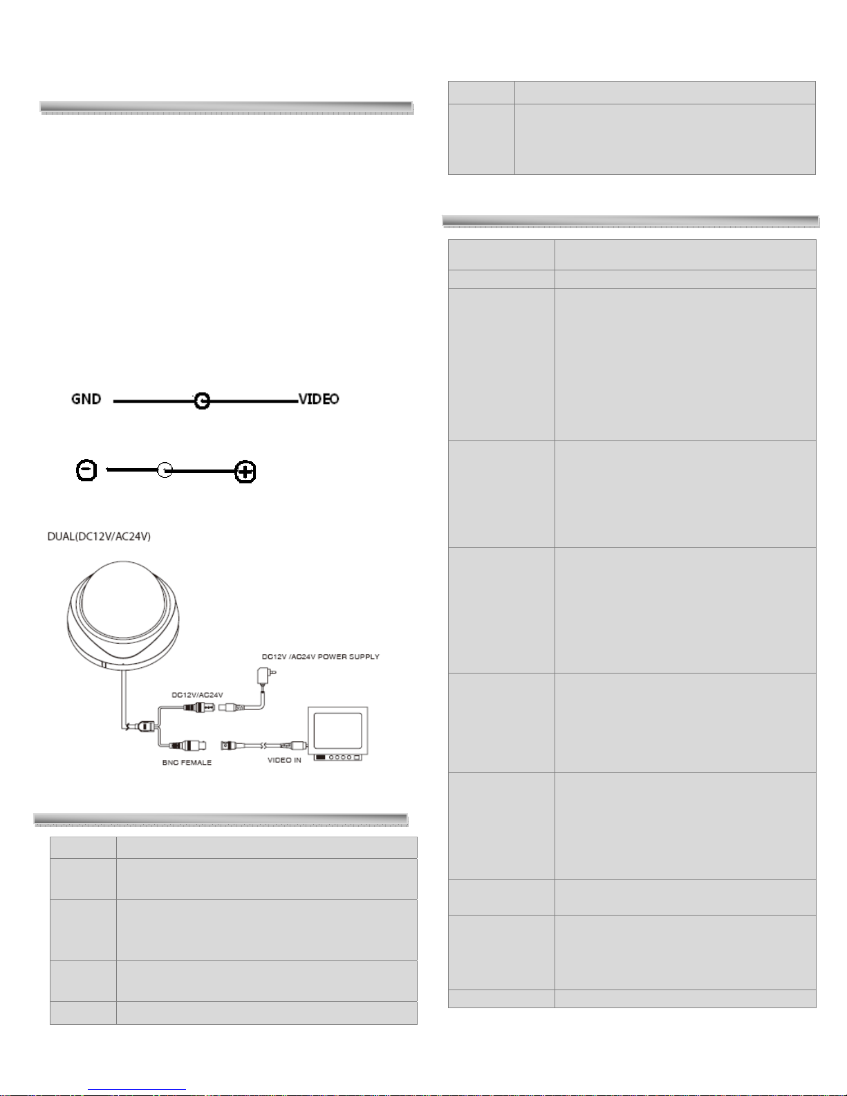
CONNECTIONS:
The functions of connecting plugs or terminals are as
below:
Video Output terminal, BNC or RCA
DC 12V power supply plug
SETUP MENU
MAIN MENU SUBMENU
Initial set
General
Backlight
Privacy
ELEC
• CAMERA ID
• MIRROR
• HI-RESOLUTION
• SHARPNESS
• COLOR SUPRESS
• APERTURE SUPRESS
• HIGHLIGHT SUPRESS
• THRESHOLD LEVEL
• EXIT
• BACKLIGHT MODE
• AREA 1 • AREA 2 • AREA 3 • AREA 4 •
AREA 5
• SENS
• GAIN
• UNWEIGHTED LEVEL
• EXIT TO MENU
• MASK NUMBER
• MASK SET
• HORIZONTAL START POSITON
• HORIZONTAL END POSITION
• VERTICAL START POSITION
• VERTICAL END POSITION
• MASK COLOR
• BACK TO MENU
TROUBLESHOOTING
Problem Solution
No
Video
Image
not
Clear
Weak
Contrast
Flicker Check whether the camera face to the sun
Check the power supply and line connection
between the camera and monitor.
• Check the surface of the lens
• Check the focus of the lens and refocus it.
Check whether the camera is exposed under
too strong light or not
WBC mode
• PUSH
• MANUAL WB
• INDOOR
• FLUORESCENT LIGHT
• OUTDOOR
• EXIT TO MENU
AE mode
Anti color
• AE MODE
• AE
• AI
• AE SHUTTER
• MANUAL
• SHUTTER
• BACK TO MENU
• ON / OFF
rolling
Flicker less
Exit
• OFF
• NORMFLC
• LLFLC
• FIXSHTFLC
• RETURN

GENERAL
It incorporates the general parameter settings, on selecting
the General option following selection panel appears on the
main screen of the monitor.
GENERAL
CAMERA ID
COLOR
MIRROR
HI-RESOLUTION
SHARPNESS
COLOR-SUPRESS
APERTURE SUPRESS
HIGHLIGHT SUPRESS
THRESHOLD LEVEL
EXIT
Camera ID
GENERAL
CAMERA ID Í
COLOR
MIRROR
• When the SETUP menu screen is displayed, select
GENERAL by using the Function Setup switch so that
COLOR is visible on the screen.
• Select a desired mode using the Function Setup switch.
• In order to exit the menu, use the function key to move
the pointer up & down and then select ‘EXIT’ to move
out to main menu.
• ## In context with the usage of this functio n the overall
color for the given picture can be enhanced up to a
larger extent than what it is actually in disabled mode.
Note:‐ When‘Color’ modeisin‘ON’state‘Color
Suppress’functioncannotbeused.
Selection Mode: - ON/OFF
MIRROR
CAMERA ID
MIRROR Í
HI-RESOLUTION
GENERAL
• When the SETUP menu screen is displayed, select
GENERAL by using the Function Setup switch so that
CAMERA ID is visible on the screen.
• Select a desired value using the Function Setup switch.
## Naming of cameras from 1 to 255 can be done with
this function depending upon availability of camera
inputs.
• In order to exit the menu, use the function key to move
the pointer up & down and then select ‘EXIT’ to move
out to main menu.
COLOR
CAMERA ID
COLOR Í
MIRROR
GENERAL
• When the SETUP menu screen is displayed, select
GENERAL by using the Function Setup switch so that
MIRROR is visible on the screen.
• Select a desired mode using the Function Setup switch.
• In order to exit the menu, use the function key to move
the pointer up & down and then select ‘EXIT’ to move
out to main menu.
• ## Switching between Normal and Inverted video
image can be obtained with this function.
• ON: - Mirror / Inverted Image OFF: - Normal Image
HI-RESOLUTION
MIRROR
HI-RESOLUTION Í
SHARPNESS
GENERAL
• When the SETUP menu screen is displayed, select
GENERAL by using the Function Setup switch so that
HI-RESOLUTION is visible on the screen.

• Select a desired mode using the Function Setup switch.
• In order to exit the menu, use the function key to move
the pointer up & down and then select ‘EXIT’ to move
out to main menu.
## Four different modes such as ‘OFF, LOW, MID, HIGH’
can be selected to increase the clarity with this function.
## As on moving fro m ‘Low to High Resol ution’ mode the
overall picture clarity goes on increasing.
extent thereby increasing the overall picture quality of
the system.
NOTE: - This function works only if the ‘COLOR’
is set to OFF mode and vice-versa.
## Under ‘High Resolution’ mode the extent of the
visibility of the objects increases to a greater extent.
SHARPNESS
GENERAL
HI RESOLUTION
SHARPNESS Í
COLOR SUPRESS
• When the SETUP menu screen is displayed, select
GENERAL by using the Function Setup switch so that
SHARPNESS is visible on the screen.
• Select a desired mode using the Function Setup switch.
• ## ‘Sharpness’ describes the clarity of detail in a video,
and can be a valuable creative tool for emphasizing
texture.
• n order to exit the menu, use the functi on key to move
the pointer up & down and then select ‘EXIT’ to move
out to main menu.
COLOR SUPRESS
SHARPNESS
COLOR SUPRESS Í
APERTURE SUPRESS
GENERAL
• When the SETUP menu screen is displayed, select
GENERAL by using the Function Setup switch so that
COLOR SUPRESS is visible on the screen.
• Select a desired mode using the Function Setup switc h.
• ## With the use of Color Suppress excess amount of
color in the video can be lowered down to a certain
APERTURE SUPRESS
GENERAL
COLOR SUPRESS
APERTURE SUPRESS Í
HIGHLIGHT SUPRESS
• When the SETUP menu screen is displayed, select
GENERAL by using the Function Setup switch so that
APERTURE SUPRESS is visible on the screen.
• Select a desired mode using the Function Setup switch.
• In order to exit the menu, use the function key to move
the pointer up & down and then select ‘EXIT’ to move
out to main menu.
• ## It helps in the regulation of the time dur ation for the
lens exposure to the light signal, thereby increasing or
decreasing the extent of light exposure on the lens.
• ON: - Suppression mode, OFF: - Normal mode
HIGHLIGHT SUPRESS
APERTURE SUPRESS
HIGHLIGHT SUPRESS Í
THRESHOLD LEVEL
GENERAL
• When the SETUP menu screen is displayed, select
GENERAL by using the Function Setup switch so that
HIGHLIGHT SUPRESS is visible on the screen.
• Select a desired mode using the Function Setup switch.
• In order to exit the menu, use the function key to move
the pointer up & down and then select ‘EXIT’ to move
out to main menu.
## This function is used to highlight those areas where the
impact of light is concentrated.

## Range provided provides an added advantage to
highlight that area on user’s interest.
THRESHOLD LEVEL
GENERAL
HIGHLIGHT SUPRESS
THRESHOLD LEVEL Í
EXIT
BACKLIGHT MODE SEL
BACKLIGHT MODE
GAIN
UNWEIGHTED LEVEL
BACK TO MENU
• When the BACKLIGHT MODE SEL screen is
displayed, select ‘BACKLIGHT MODE’ by using the
Function Setup switch so that the arrow indicates
BACKLIGHT.
• When the SETUP menu screen is displayed, select
GENERAL by using the Function Setup switch so that
HIGHLIGHT SUPRESS is visible on the screen.
• Select a desired mode using the Function Setup switch.
• In order to exit the menu, use the function key to move
the pointer up & down and then select ‘EXIT’ to move
out to main menu.
• ## It is the extent beyond which the change in the
overall picture quality is visible.
BACKLIGHT
This camera is designed so that it delivers a distinctive
subject and background at the same time, even when the
subject is in backlight, unlike conventional cameras, by
adopting a proprietary SONY CXD 3172 AR DSP chip.
BACKLIGHT MODE SELECTION
INITIAL SET EXEC
GENERAL
BACKLIGHT OFF Í
PRIVACY OFF
WBC MODE PUSH
AE MODE AE
ANTI-COLOR ROLLING OFF
FLICKERLESS OFF
MAIN MENU
• When the MAIN MENU screen is displayed, select
‘BACKLIGHT’ by using the Function Setup swit ch so
that the arrow indicates BACKLIGHT.
• Select a desired mode using the Function Setup switch
depending on the camera purpose.
• Select a desired mode using the Function Setup switch
depending on the camera purpose.
It enables the Switching of the Backlight
Compensation mode from off to on.
In the SENS mode auto adjustment of
backlight can be done to the overall video.
As the screen is divided into 5 different
portions. So, the user can individually
select different areas of his interest for the
optimization of Backlight from the given
options such as AREA 1 to AREA 5.
Area selection involves the overall increase in
quality of the picture.
• Selection is to be made from the following options
AREA 1, AREA 2, AREA 3, AREA 4, AREA 5,
SENS, OFF.
• In order to exit the menu, use the function key to move
the pointer up & down and then select ‘EXIT’ to move
out to main menu.
GAIN
• When the BACKLIGHT MODE SEL screen is
displayed, select ‘GAIN’ by using the Function Setup
switch so that the arrow indicates GAIN.
• Select a desired mode using the Function Setup switch
depending on the camera purpose.
• In order to exit the menu, use the function key to move
the pointer up & down and then select ‘EXIT’ to move
out to main menu.

UNWEIGHTED MODE
• When the BACKLIGHT MODE SEL screen is
displayed, select ‘UNWEIGHTED MODE’ by using
the Function Setup switch so that the arrow indicates
UNWEIGHTED MODE.
• Select a desired mode using the Function Setup switch
depending on the camera purpose.
• In order to exit the menu, use the function key to move
the pointer up & down and then select ‘EXIT’ to move
out to main menu.
By the selection of the particular area of our concern we
can optimize the effect of Backlight through with this
parameter within a range of 000 to 015 numerical value.
PRIVACY MASKING
This function enables the user to select an area which
he/she does not want to be included in the Live/Playback
mode.
MAIN MENU
INITIAL SET EXEC
GENERAL
BACKLIGHT OFF
PRIVACY OFFÍ
WBC MODE PUSH
AE MODE AE
ANTI-COLOR ROLLING OFF
FLICKERLESS OFF
EXIT Í
• Horizontal Start Position- Marking can be done
on the x-axis on the screen depicting starting
point of masked area, such as from where the
area under privacy masking starts.
• Horizontal End Position- Marking can be done
on the x-axis on the screen depictin g end point
of masked area.
• Vertical Start Position- Marking can be done on
the y-axis on the screen depicting start point of
masked area.
• Vertical End Position- Marking can be done on
the y-axis on the screen depicting end point of
masked area.
• Mask Color- Customization of the masked space
can be done with this function to the desired color
present.
Available choices for the user are as follows -
Orange, Yellow, Green, Blue, Purple, Hold, Grey,
White, Red, Black.
WBC MODE
It enable Automatic white balance correction or as per
defined by the user settings by ‘PUSH’ selection. White
Balance Control mode enables the correction or control
related to excess of brightness involved in the picture.
MAIN MENU
INITIAL SET EXEC
GENERAL
BACKLIGHT OFF
PRIVACY OFF
WBC MODE PUSHÍ
AE MODE AE
ANTI-COLOR ROLLING OFF
FLICKERLESS OFF
• When the MAIN MENU screen is displayed, select
‘PRIVACY’ by using the Function Setup switch so that
it starts blinking.
• Select a desired mode using the Function Setup switch
depending on the camera purpose.
• MASK NUMBER- It enables us to select eight
different locations on the screen from a range 000
to 008 that wish not to be recorded or are to be
eliminated.
• MASK SET- It enables the user to select or deselect
to mark the shape and size of area to be omitted
through the selection options ON/OFF.
Under ON state following parameters are enabled.
• When the MAIN MENU screen is displayed, select
‘WBC MODE’ by using the Function Setup switch so
that it starts blinking.
• Select a desired mode using the Function Setup switch
depending on the camera purpose.
PUSH
MANUAL WB
INDOOR
FLOURECENT LIGHT
OUTDOOR
WBC MODE

• PUSH- It adjusts the white Balance to a predefined
value under initiated state. Toggle from high state to
low state can be done by simply selecting ‘ON’ and
vice-versa.
• MANUAL WB- It allows the user to adjust White
Balance accordingly to the environmental conditions
and preference. User can set the value according to his
preferences.
• INDOOR- This parameter adjusts the WB accordingly
to the indoor light conditions, as for the indoor
conditions values are preloaded in the program.
• FLOURECENT LIGHT- This parameter adjusts the
WB accordingly to the fluorescent light conditions and
temperature.
• OUTDOOR- This parameter adjusts the WB
accordingly to the outdoor light conditions.
• In order to exit the menu, use the function key to move
the pointer up & down and then select ‘EXIT’ to move
out to main menu.
AE
INITIAL SET EXEC
GENERAL
BACKLIGHT OFF
PRIVACY OFF
WBC MODE PUSH
AE MODE AE Í
ANTI-COLOR ROLLING OFF
FLICKERLESS OFF
EXIT Í
MAIN MENU
It enables the adjustment of the shutter opening and closi ng
automatically or accordingly to the values modified by the
user himself depending upon the picture required.
• When the MAIN MENU screen is displayed, select ‘AE
MODE’ by using the Function Setup switch so that it
starts blinking.
• Select a desired mode using the Function Setup switch
depending on the camera purpose.
AE ON/OFF
AI ON/OFF
AE SHUTTER ON/OFF
MANUAL
• SHUTTER
• GAIN
BACK TO MENU Í
AE MODE
• AE- This function enables or disables the automatic
opening and closing of the electronic shutter with
the change in light conditions, thereby increasing or
decreasing the amount of light falling on the CCD.
• AI- It configures the functioning for the Auto IRIS
or disables it, thereby configuring the automatic
opening and closing of the shutter depending upon
the light falling on it.
• AE SHUTTER- With this function we can set the
shutter exposure speed within a range of predefined
values listed below.
1/50, 1/120, 1/250, 1/500, 1/1k, 1/2k, 1/4k, 1/10k,
1/100k, these values shows the opening of the
shutter per unit time. While using this function
FLICKERLESS should be closed.
• MANUAL
• SHUTTER- With this function we can set the
shutter exposure speed within a range of
predefined values listed below.
• GAIN-1/50, 1/120, 1/250, 1/500, 1/1k, 1/2k,
1/4k, 1/10k, 1/100k, these values shows the
opening of the shutter per unit time. And
alongside the GAIN value between 5db, 13db,
22db, 30db.
• In order to exit the menu, use the function key to
move the pointer up & down and then select
‘EXIT’ to move out t o main menu.

ANTI COLOR ROLLING
It reduces the effect of color change during Flicker less
control mode when enabled and vice-versa. It reduces the
color spectrum formed when the camera is focused on the
fluorescent light
MAIN MENU
INITIAL SET EXEC
GENERAL
BACKLIGHT OFF
PRIVACY OFF
WBC MODE PUSH
AE MODE AE
ANTI-COLOR ROLLING OFFÍ
FLICKERLESS OFF
EXIT Í
• When the MAIN MENU screen is displayed, select
‘FLICKERLESS’ by using the Function Setup switch
so that it starts blinking.
• Select a desired mode using the Function Setup switch
depending on the camera purpose.
Flicker less control actually takes into account the
cycling process of the light sources and adjusts the
color, gain, ESC and white tracking balance to produce
a correct color picture.
It makes use of three parameters
1. NORMFLC
2. LLFLC
3. FIXSHTFLC
Selection ranges between OFF, NORMAL, LLFLC,
FIXSH.
• When the MAIN MENU screen is displayed, select
‘Anti Color Rolling’ by using the Function Setup
switch so that it starts blinking.
• Select a desired mode using the Function Setup switch
depending on the camera purpose.
• Whether to turn ON this function or not.
• In order to exit the menu, use the function key to move
the pointer up & down and then select ‘EXIT’ to move
out to main menu.
FLICKERLESS
MAIN MENU
INITIAL SET EXEC
GENERAL
BACKLIGHT OFF
PRIVACY OFF
WBC MODE PUSH
AE MODE AE
ANTI-COLOR ROLLING OFF
FLICKERLESS OFF Í
EXIT Í
• In order to exit the menu, use the function key to move
the pointer up & down and then select ‘EXIT’ to move
out to main menu.
EXIT
MAIN MENU
INITIAL SET EXEC
Press the Function Setup switch in the EXIT menu to save the
current settings and exit the SET menu.
GENERAL
BACKLIGHT OFF
PRIVACY OFF
WBC MODE PUSH
AE MODE AE
ANTI-COLOR ROLLING OFF
FLICKERLESS OFF
EXIT Í

SPECIFICATION
MODEL SP-354DO SP-354DA49O SP-354CSNO SP-354CTNO
Camera Type Dome Varifocal Dome Box Camera
Image sensor 1/3 “ SONY SUPER HAD-II CCD
Effective Pixels NTSC : 768 (H) x 494 (V), PAL : 752 (H) x 582 (V)
Horizontal Resolution 760 H
Operation Area Indoor Indoor Indoor Indoor
System View PAL/NTSC
OSD English
3.6 mm Board Lens
Lens
Video output level 1.0vp-p (75 Ohms Composite Video Out)
Resolution 540 TVL
Day & Night No No No Yes (ICR)
Optional Lens: 2.5 / 6 / 8 /
12 / 16 / 25 mm
Built in 4-9 / F 1.6
Optional 2.8-10 mm / F
1.6
C/CS Mount
Day& Night Box
Camera
Min. Illumination 0.05 LUX
White Balance (Push, Manual, Indoor, Outdoor, Fluorescent light)
(AE/ME) Exposure (AE, AI, Shutter, AE Shutter, Manual)
Back Light Compensation (Backlight Mode, Gain, Unweighted Level)
HSBLC ON/OFF
MIRROR ON/OFF
FLICKER FREE MODE OFF, NORM, LLFLC, FIXSH
5 Switch Menu Function
Control
Privacy Mask Function ON/OFF (8 Areas)
SHARPNESS ON/OFF
Input Voltage 12 V DC 12 V DC 12 V DC 12 V DC
Current Drawn Approx. 200 m A Approx. 200 m A Approx. 300 m A Approx. 300 m A
MENU, UP/DOWN, RIGHT/LEFT
Operating
Temperature/Humidity
0°C to +50°C / 30% to 80% RH

IR CAMERA SERIES SP-354IROXX
Model NO SP-354IROXX W
354- 1/3” sensor with 540 TVL Resolution
IRO- Bravura IR series
XX – IR Distance - 30,40,50,70 Mtr.
W – With Fan
IR Distance IR LEDs
30 mtr. 36 pcs. 850 nm /Ø 5 mm
40 mtr. 48 pc s. 850 mm / Ø 5 mm
50 mtr. 60 pc s. 850 n m/ Ø 5 mm
70 mtr. 12 pc s. 850 mm / Ø 10 mm
MODEL
Camera Type IR Box
Image sensor 1/3 “ SONY SUPER HAD-II CCD
Effective Pixels NTSC : 768 (H) x 494 (V), PAL : 752 (H) x 582 (V)
Horizontal Resolution 760 H
Operation Area Outdoor Outdoor Outdoor Outdoor Outdoor
SP-354IROXXXX
SP-54IR49LO
Vandal Proof
Varifocal IR Dome
SP-354IRD49O SP-354IR49O NPRO-354
Varifocal IR Dome
Vari Focal IR
Camera
Number Plate
Reader Camera
System View PAL/NTSC
OSD English
Optional Lens: 2.5/3.6
/ 6 / 8 / 12 / 16 / 25
Lens
Video output level 1.0vp-p (75 Ohms Composite Video Out)
Resolution 540 TVL
IR Distance 30,40,50,70 Mtr. 10-30 Mtr. 10-30 Mtr. 10-30 Mtr. 30,40,50,70 Mtr.
Min. Illumination 0.05 LUX
White Balance Push, Manual, Indoor, Outdoor, Fluorescent light
(AE/ME) Exposure AE, AI , AE Shutter, Manual
Back Light
Compensation
mm
Built in 4-9 / F 1.6
Optional 2.8-10 mm /
F 1.6
Backlight Mode, Gain, Unweighted Level
Built in 4-9 / F 1.6
Optional 2.8-10
mm / F 1.6
Built in 4-9 / F
1.6 Optional
2.8-10 mm / F
1.6
3.6 mm Board
Lens
Optional Lens:
2.5/6 / 8 / 12 / 16 /
25 mm
HSBLC ON/OFF
MIRROR ON/OFF
FLICKER FREE
OFF, NORM, LLFLC, FIXSH

MODE
5 Switch Menu
Function Control
Privacy Mask
Function
SHARPNESS ON/OFF
I/O Connectors DC FEMALE / BNC FEMALE
Operating
Temperature/Humidity
Input Voltage 12 V DC 12 V DC 12 V DC 12 V DC 12 V DC
MENU, UP/DOWN, RIGHT/LEFT
ON/OFF (8 Areas)
0°C to +50°C / 30% to 80% RH

Samriddhi Automations Private Limited
Corporate Office: F-365, Sector – 63 Noida, U.P. (India) Tel: + 91 - 120 - 45 18 900 (20 Lines)
Works: Plot No. : 75, Sector - 7, I.I.E., SIDCUL, Haridwar (India) Tel: + 91- 01334 - 645 011, 239 396
Service Center: A - 1 / 15, New Kondli, New Delhi. (India) Tel: 91-11-2262 3325
info@sparshsecuritech.com | www.sparshsecuritech.com
 Loading...