

Sparsh 540 TVL OSD Camera Series, SP-354DO, SP-354DA49O, SP-354CSNO, SP-354CTNO User Manual
...
540 TVL OSD Camera Series
User Manual
V1.0

DESCRIPTION
The camera uses SONY charge coupled device (CCD)
image sensor, and employs digital signal processing
(DSP) chip-set for image control, and all integrated
state circuitry which provides extremely long life and
high reliability. This camera offers excellent image
quality, and is not subject to distortions from magnetic
fields. High resistance to shock and vibration, and easy
to install, this camera is the best choice for your CCTV
system.
TRADEMARKS
Optimum operational temperature range is 0°C and
+50°C.
• Do not install under varying light conditions.
Continuously varying light frequency might cause
problems in the normal functioning of the camera.
• Do not put camera under shocks and jerks.
This may cause the serious disorientation or the
distortion in the components thereby causing the
malfunctioning of the product.
• Do not install under excess of humid conditions.
Sparsh logo is registered trademarks of Samriddhi
Automations Pvt. Ltd.
SONY, SONY Super HAD & SONY Super HAD-II is
registered trademark of Sony Incorporation.
All other brand, product names, and service names are
trademarks or registered trademarks of their respective
companies or organizations
LIMITATION OF LIABILITY
• This publication is provided “as is” without warranty of
any kind, either express or implied, including but not
limited to, the implied warranties of merchantability,
fitness for any particular purpose, or non-infringement of
the third party’s right.
• This publication could include technical inacc uracies or
typographical errors. Changes are added to the
information herein, at any time, for the improvements of
the publications and/or the corresponding pr oduct(s).
This may cause the deposition of water droplets on the
lens and several other sensitive components thereby
lowering the picture quality.
• Do not expose the camera directly to high light intensity
pulse.
This may damage the C CD or may create de ad pixels in
the CCD.
• Do not expose camera to water.
This may result in malfunctioning of the camera or may
result in the corrosion of certain components due to
minerals contained in water.
• Do not expose camera to radioactivity.
Radioactive exposure may cause damage to CCD or may
produce dead pixels.
• Do not attempt to open the camera.
Unauthorized opening of camera is not permissible as it
could cause breakage of the fragile components.
WARNINGS & CAUTIONS
• The information provided in the user manual is for the
safety of the customers. Please read the user manual
before operating the product and follow the instructions
provided accordingly.
Warning Messages
• Do not install under excess hot conditions.
• Do not use low quality cables and power supply.
Only recommended cables/wires and power supply
should be used for proper functioning of the camera.
If any abnormality occurs, make sure to unplug the unit
and contact your local dealer or our service centre.
INSTALLATION
•
• Installation must be carried out by the authorized
personals only.
Image directly or strong light
Noise in
Video
Check illumination is low or not
• Check power supply voltage is low or not
• Check proper wire connectivity
• Surface on which the camera is to be mounted must be
strong enough to hold the camera firmly, if not so
reinforce the surface again so that the camera may not
fall off the surface.
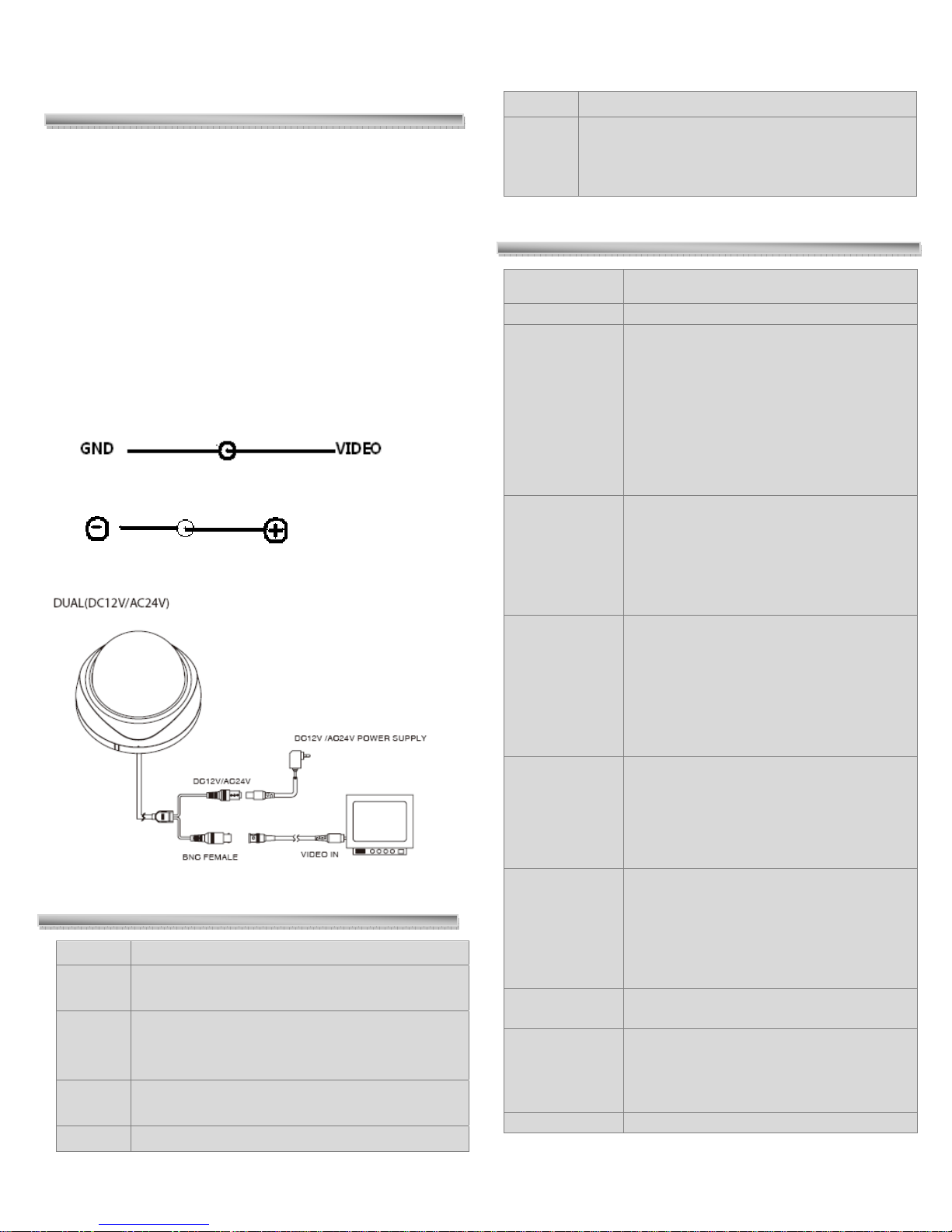
CONNECTIONS:
The functions of connecting plugs or terminals are as
below:
Video Output terminal, BNC or RCA
DC 12V power supply plug
SETUP MENU
MAIN MENU SUBMENU
Initial set
General
Backlight
Privacy
ELEC
• CAMERA ID
• MIRROR
• HI-RESOLUTION
• SHARPNESS
• COLOR SUPRESS
• APERTURE SUPRESS
• HIGHLIGHT SUPRESS
• THRESHOLD LEVEL
• EXIT
• BACKLIGHT MODE
• AREA 1 • AREA 2 • AREA 3 • AREA 4 •
AREA 5
• SENS
• GAIN
• UNWEIGHTED LEVEL
• EXIT TO MENU
• MASK NUMBER
• MASK SET
• HORIZONTAL START POSITON
• HORIZONTAL END POSITION
• VERTICAL START POSITION
• VERTICAL END POSITION
• MASK COLOR
• BACK TO MENU
TROUBLESHOOTING
Problem Solution
No
Video
Image
not
Clear
Weak
Contrast
Flicker Check whether the camera face to the sun
Check the power supply and line connection
between the camera and monitor.
• Check the surface of the lens
• Check the focus of the lens and refocus it.
Check whether the camera is exposed under
too strong light or not
WBC mode
• PUSH
• MANUAL WB
• INDOOR
• FLUORESCENT LIGHT
• OUTDOOR
• EXIT TO MENU
AE mode
Anti color
• AE MODE
• AE
• AI
• AE SHUTTER
• MANUAL
• SHUTTER
• BACK TO MENU
• ON / OFF
rolling
Flicker less
Exit
• OFF
• NORMFLC
• LLFLC
• FIXSHTFLC
• RETURN

GENERAL
It incorporates the general parameter settings, on selecting
the General option following selection panel appears on the
main screen of the monitor.
GENERAL
CAMERA ID
COLOR
MIRROR
HI-RESOLUTION
SHARPNESS
COLOR-SUPRESS
APERTURE SUPRESS
HIGHLIGHT SUPRESS
THRESHOLD LEVEL
EXIT
Camera ID
GENERAL
CAMERA ID Í
COLOR
MIRROR
• When the SETUP menu screen is displayed, select
GENERAL by using the Function Setup switch so that
COLOR is visible on the screen.
• Select a desired mode using the Function Setup switch.
• In order to exit the menu, use the function key to move
the pointer up & down and then select ‘EXIT’ to move
out to main menu.
• ## In context with the usage of this functio n the overall
color for the given picture can be enhanced up to a
larger extent than what it is actually in disabled mode.
Note:‐ When‘Color’ modeisin‘ON’state‘Color
Suppress’functioncannotbeused.
Selection Mode: - ON/OFF
MIRROR
CAMERA ID
MIRROR Í
HI-RESOLUTION
GENERAL
• When the SETUP menu screen is displayed, select
GENERAL by using the Function Setup switch so that
CAMERA ID is visible on the screen.
• Select a desired value using the Function Setup switch.
## Naming of cameras from 1 to 255 can be done with
this function depending upon availability of camera
inputs.
• In order to exit the menu, use the function key to move
the pointer up & down and then select ‘EXIT’ to move
out to main menu.
COLOR
CAMERA ID
COLOR Í
MIRROR
GENERAL
• When the SETUP menu screen is displayed, select
GENERAL by using the Function Setup switch so that
MIRROR is visible on the screen.
• Select a desired mode using the Function Setup switch.
• In order to exit the menu, use the function key to move
the pointer up & down and then select ‘EXIT’ to move
out to main menu.
• ## Switching between Normal and Inverted video
image can be obtained with this function.
• ON: - Mirror / Inverted Image OFF: - Normal Image
HI-RESOLUTION
MIRROR
HI-RESOLUTION Í
SHARPNESS
GENERAL
• When the SETUP menu screen is displayed, select
GENERAL by using the Function Setup switch so that
HI-RESOLUTION is visible on the screen.
 Loading...