

Sparsh SE4204, SE4208, SE1216 User Manual

H.264 Network Digital Video Recorder User Manual
USERMANUAL
eYeSeriesDVR
DualStreaming
H.264Multiplex4CH/8CH/16ChNetworkDVR
Model: SE4204/SE4208/SE1216

H.264 Network Digital Video Recorder User Manual
Welcome
Thank you for purchasing our DVR!
This manual is designed to be a reference tool for the installation and operation of your system.
Here you can find information about this series DVR features and functions, as well as a detailed menu tree.
Before installation and operation please read the following safeguards and warnings carefully!
Important Safeguards and Warnings
Do not place the heavy object on the DVR.
Do not let any solid or liquid fall into or infiltrate the DVR.
Please brushing the printed circuit boards, connectors, fans, machine box a nd so on regularly. Before the dust
cleaning please switch off the power supply and unplug it.
Do not disassemble or repair the DVR by yourself. Do not replace the electronic components by yourself.
Environment
A void dir e ct sunlight. Stay away from heat source.
Do not install the DVR in damp environ ment.
Do not use the DVR in smoky or dusty environment.
A void collision or str ong fall.
Please insure the DVR level installation in a stable workplace.
Please install in ventilated place. Keep the vent clean.
Use within the rating input and output scope.
Page 2

H.264 Network Digital Video Recorder User Manual
Directory
1 Production Introduction ................................................................................................................................ 5
1.1 Product overview ............................................................................................................................... 5
1.2 Main functions .................................................................................................................................... 5
2 Open-package check and cable connections ............................................................................................... 7
2.1 Open-package check ......................................................................................................................... 7
2.2 Hard disk installation .......................................................................................................................... 7
2.3 Front panel ......................................................................................................................................... 8
2.4 Rear panel ......................................................................................................................................... 8
2.5 Audio and video input and output connections ................................................................................... 9
2.5.1 Video input connections ........................................................................................................... 9
2.5.2 Video output connections and options ..................................................................................... 9
2.5.3 Audio signal input ...................................................................................................................10
2.5.4 Audio signal output .................................................................................................................10
2.6 Speed dome connections ..................................................................................................................10
3 Basic operation ........................................................................................................................................... 11
3.1 Turn on.............................................................................................................................................. 11
3.2 Turn off .............................................................................................................................................. 11
3.3 System Login .................................................................................................................................... 11
3.4 Preview .............................................................................................................................................12
3.5 Desktop shortcut menu .....................................................................................................................12
3.5.1 Main menu ..............................................................................................................................12
3.5.2 Playback .................................................................................................................................13
3.5.3 Record Mode ..........................................................................................................................17
3.5.5 PTZ control .............................................................................................................................17
3.5.6 Color setting ...........................................................................................................................21
3.5.7 Output adjust ..........................................................................................................................21
3.5.8 Logout ....................................................................................................................................22
3.5.9 Window switch ........................................................................................................................22
4 Main menu ..................................................................................................................................................23
4.1 Main menu navigation .......................................................................................................................23
4.2 Record ..............................................................................................................................................26
4.2.1 Record Config ........................................................................................................................26
4.2.3 Playback .................................................................................................................................28
4.2.4 Backup ...................................................................................................................................28
4.3 Alarm ................................................................................................................................................26
4.3.1 Motion Detect .........................................................................................................................26
4.3.2 Video Blind .............................................................................................................................29
4.3.3 Video Loss ..............................................................................................................................29
Page 3

H.264 Network Digital Video Recorder User Manual
4.3.6 Abnormal ................................................................................................................................30
4.4 System ..............................................................................................................................................34
4.4.1 General...................................................................................................................................34
4.4.2 Encode ...................................................................................................................................35
4.4.3 Network ..................................................................................................................................37
4.4.4 NetSevice ...............................................................................................................................37
4.4.5 GUI Display ............................................................................................................................43
4.4.6 PTZ ........................................................................................................................................45
4.4.8 Tour ........................................................................................................................................45
4.5 Advanced ..........................................................................................................................................46
4.5.1 HDD Manage ..........................................................................................................................46
4.5.2 Account...................................................................................................................................47
4.5.3 Online user .............................................................................................................................50
4.5.4 Output adjust ..........................................................................................................................50
4.5.5 Auto maintain ..........................................................................................................................51
4.5.6 Restore ...................................................................................................................................47
4.5.7 Upgrade..................................................................................................................................52
4.5.8 Device Info........................................................................................................................52
4.6 Info ....................................................................................................................................................48
4.6.1 HDD info .................................................................................................................................48
4.6.2 BPS ........................................................................................................................................49
4.6.3 Log .........................................................................................................................................49
4.6.4 Version ...................................................................................................................................50
4.7 Shut down system .............................................................................................................................50
5 FAQ and maintenance .................................................................................................................................51
5.1 FAQ ..................................................................................................................................................51
5.2 Maintenance .....................................................................................................................................55
Appendix 1.Remote controller operation ........................................................................................................56
Appendix 2.Mouse operation ..........................................................................................................................57
Appendix 3.Hard disk capability calculation ....................................................................................................58
Appendix 4.Technique parameters .................................................................................................................59
Page 4

H.264 Network Digital Video Recorder User Manual
Page 5

H.264 Network Digital Video Recorder User Manual
1 Production Introduction
1.1 Product overview
The series DVR is designed specially for security and defense field which is an outstanding digital surveillance
product. It introduces embedded LINUX operating system which is more stable. It introduces standard
H.264mp video compressed format and G.711A audio compressed format which insures the high quality
image, low error coding ratio and single frame playing. It introduces TCP/IP network technology which
achieves the strong network communication ability and telecommunication ability.
The series DVR can be used individually or online applied as a part of a safety surveillance network. With the
professional network video surveillance software it achieves the strong network communication ability and
telecommunication ability.
The series DVR can be applied in the bank, telecom, electric power system, judicial system, transportation,
intelligent housing, factory, storehouse, water conservancy and so on.
1.2 Main functions
Real-time surveillance
Analog interface and VGA interface (VGA interface is equipped selectively) Surveillance function through
monitor or display
Storage
Non-working hard disk dormancy processing which is convenient to radiate heat, reduce power and extend
the life-span special storage format which insures the data safety
Compression
Real-time compression by individual hard disk which insures the audio and video signal stable synchronization
Backup
Through SATA interface and USB interface such as USB equipment, removable hard disk and so on
through net download the files in the hard disk
Playback
Individual real-time video recording as well as searching, playback, network surveillance, recording check,
downloading and so on multi-playback mode, zoom at arbitrary region
Net operating
Through net tele-surveillance in the real time
Tele-PTZ control
tele-recording check and real-time playback
Alarm linkage
multi-route relay alarm output which is convenient for the alarm linkage and light control at the spot
protecting circuits at the alarm input and output interface which protects the main machine from damage
Communication interface
RS485 interface which fulfills the alarm input and PTZ control
Page 6

H.264 Network Digital Video Recorder User Manual
standard ethernet network interface which fulfills the telecommuting function
Intelligent operating
mouse action function
fast copy and paste operating for the same setting
Page 7
H.264 Network Digital Video Recorder User Manual
2 Open-package check and cable connections
2.1 Open-package check
When you receive the DVR, please check first.
First, please check whether there is any visible damage to the package appearance. The protective materials
used for the package of the DVR can protect most accidental clashes during transportation.
Then, please open the box and get rid off the plastic protective materials. Check whether there is any visible
damage to the DVR appearance.
At last, please open the machine crust and check the data wire in the front panel, power wire, the connection
between the fan power and the main board.
Front panel and rear panel
♦ The key function specification in the front panel and the interface specification in the real panel are in
the specification.
♦ Please check the product type in the front panel whether is accordant with the product type you
order.
The label in the real panel is very important for the after service. Please protect it carefully. When you
contact us for after service, please provide the product type and serial number in the label.
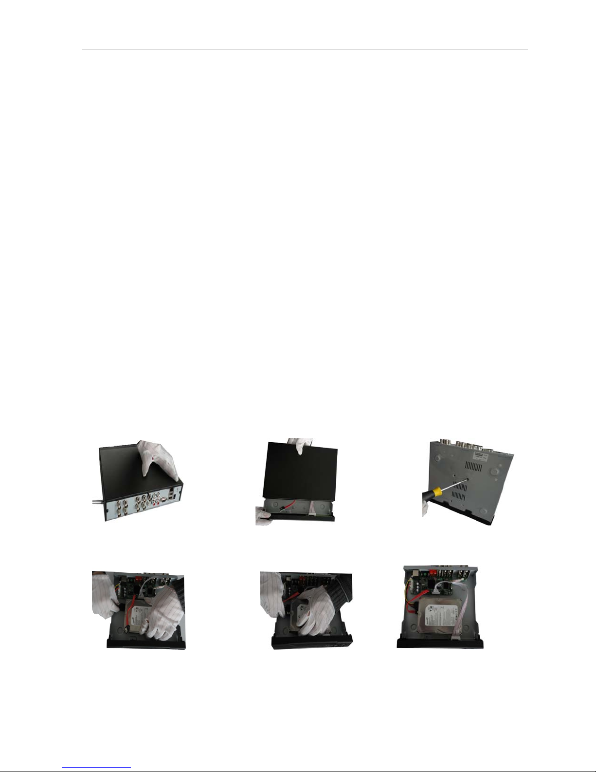
2.2 Hard disk installation
For the first use,please install the hard disk.
disassemble the screw disassemble the cover fix the screw of hard disk
connect SATA power wire connect SATA data wire the right connection
Page 8

H.264 Network Digital Video Recorder User Manual
cover the machine fix the cover
⑨ Installation finished
2.3 Front panel
(1) Power indication light (2) Record indication light (3) Alarm indication light (4) ESC
(5) Menu (6) Direction and OK
2.4 Rear panel
2.5 Audio and video input and output connections
2.5.1 Video input connections
The video input port is BNC connector plug. The demand of input signal is PAL/NTSC BNC(1.0V
The video signal must be accorded with the state standard which has the high signal to noise ratio, low
aberration and low interference. The image must be clear and has natural color in the appropriate brightness.
Page 9
,75Ω).
P-P

2.5.2 Video output connections and options
H.264 Network Digital Video Recorder User Manual
The video output is divided into PAL/NTSC BNC (1.0V
, 75Ω) and VGA output(selective configuration).
P-P
When replace the monitor by the computer display, there are some issues to notice.
1.Do not stay in the turn-on state for a long time.
2.Keep the computer display normal working by demagnetizing regularly.
3.Stay away from the electro magnetic Interference.
TV is not a credible replacement as a video output. It demands reducing the use time and control the
power supply and the interference introduced by the nearby equipments strictly. The creepage of low quality
TV can lead to the damage of other equipments.
2.5.3 Audio signal input
Audio port is BNC connection.
The input impedance is high so the tone arm must be active.
The audio signal line should be firm and away from the electro magnetic Interference and connected
credible which avoid false and joint welding and oxidation. The high voltage current should be avoided
especially.
2.5.4 Audio signal output
Commonly the output parameter of DVR audio signal is greater than 200mv 1KΩ(BNC) which can connect the
low impedance earphone and active sound box or other audio output equipments through power amplifier. If
the sound box and the tone arm can not be isolated, howling phenomena is often existed. There are some
methods to deal with the above phenomena.
1、 Adopt better directional tone arm.
2、 Adjust the sound box volume to be under the threshold that produces the howling phenomena.
3、 Use fitment materials that absorb the sound to reduce reflection of the sound.
4、 Adjust the layout of the sound box and the tone arm.
2.6 Speed dome connections
1.Connect the 485 lines of the speed dome with the DVR 485 interface.
2.Connect the video line with the DVR video input.
3.Electrify the speed domes.
Page 10

H.264 Network Digital Video Recorder User Manual
3 Basic operation
Note: The button in gray display indicates nonsupport.
3.1 Turn on
Plug the power supply and turn on the power supply switch. Power supply indicator light shining indicates
turning on the video recorder. After the startup you will hear a beep. The default setting of video output is
multiple-window output mode. If the startup time is within the video setting time, the timing video recording
function will start up automatically. Then the video indicator light of corresponding channel is shining and the
DVR is working normally.
Note: 1. Make sure that the input voltage corresponds with the switch of the DVR power supply.
2. Power supply demands: 220V±10% /50Hz.
Suggest using the UPS to protect the power supply under allowable conditions.
3.2 Turn off
There are two methods to turn off the DVR. Entering [main menu] and choosing [turn off] in the [turn off the
system] option is called soft switch. Pressing the power supply switch is called hard switch.
Illumination:
1. Auto resume after power failure
If the DVR is shut down abnormally, it can automatically backup video and resume previous working
status after power failure.
2. Replace the hard disk
Before replacing the hard disk, the power supply switch in the real panel must be turned off.
3.Replace the battery
Before replacing the battery, the setting information must be saved and the power supply switch in the real
panel must be turned off. The DVR uses button battery. The system time must be checked regularly. If the time
is not correct you must replace the battery, we recommend replacing the battery every year and using the
same battery type.
Note: The setting information must be saved before replacing the battery otherwise information will
lose.
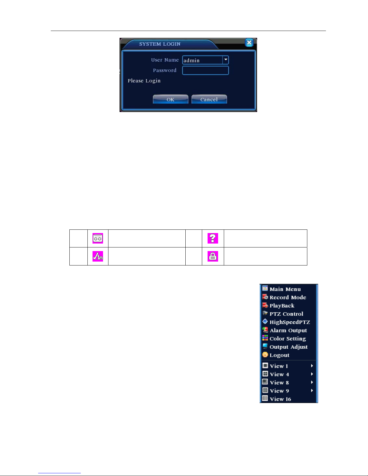
3.3 System Login
When the DVR boots up, the user must login and the system provides the corresponding functions with the
user purview. There are three user settings. The names are admin, guest and default and these names
have no password. Admin is the super user purview; guest and default’s permissions are preview and video
playback. User admin and guest’s password can be revised, while their permissions can’t be revised; user
default is the default login user whose permission can be revised but not its password.
Page 11
H.264 Network Digital Video Recorder User Manual
Picture 3.1 System Login
Password protection: If the password is continuous wrong three times, the alarm will start. If the
password is continuous wrong five times, the account will be locked. (Through reboot or after half an
hour, the account will be unlocked automatically). For your system security, please modify your
password after first l ogin.
3.4 Preview
You can right click mouse to choose the switch between the windows.
The system date, time and channel name are shown in each viewing window. The surveillance video and the
alarm status are shown in each window.
1
2
Recording status
Motion detect
3
4
Video loss
Camera lock
Table 3.1 Preview icon
3.5 Desktop shortcut menu
In preview mode you can right click mouse to get a desktop shortcut menu. The
menu includes: main menu,record mode,playback,PTZ control,High Speed
PTZ,Alarm Output,color Setting,Output adjust,Logout,view1/4/8/9/16
screens.
Picture 3.2 Shortcut Menu
3.5.1 Main menu
When you login, the system main menu is shown as below.
Page 12
H.264 Network Digital Video Recorder User Manual
Picture3.3 Main Menu
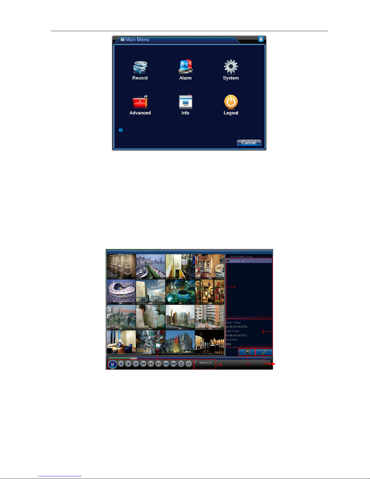
3.5.2 Playb ack
There are two methods for you to play the video files in the hard disk.
1、 In the desktop shortcut menu.
2、 Main menu>Record->Playback
Note: The hard disk that saves the video files must be set as read-write or read-only state.(4.5.1)
Picture 3.4 video playback
1. listed files 2. file information 3. file searching
4. file backup 5. Operation hint 6. Playback control
【Listed files】Look up the listed files that accord with the searching criteria.
【File information】Look up the found file information.
Page 13
H.264 Network Digital Video Recorder User Manual
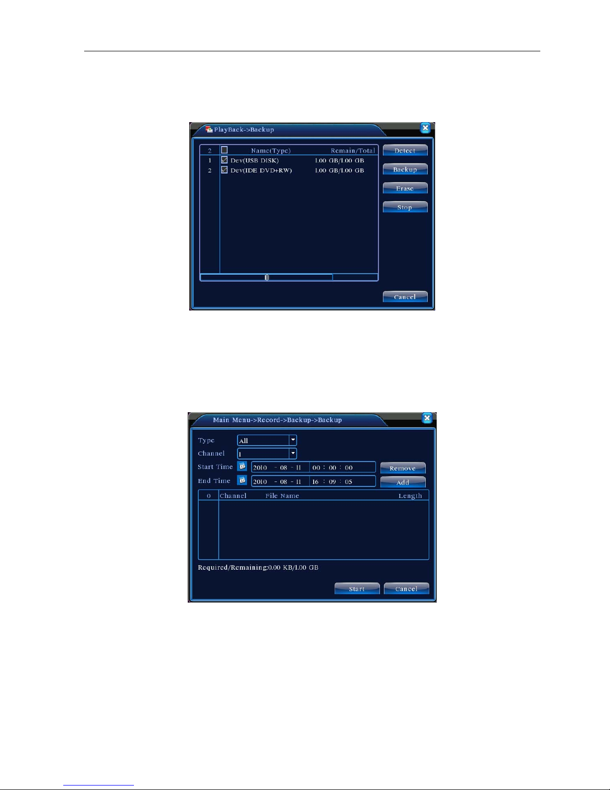
【File backup】Backup the chosen file. Click the button and operate as followed.
Note: The storage must be installed before the file backup. If the backup is terminated, the already
backup can playback individually.
Picture 3.5 detect the storage
Detect: Detect the storage connected with the DVR such as hard disk or universal disk.
Erasure: Choose the file to delete and click erasure to delete the file.
Stop: Stop the backup.
Backup: Click backup button and the dialog box is popped up. You can choose the backup file
according to the type, channel and time.
Picture 3.6 recording backup
Remove:Clear the file information.
Add:Show the file information satisfying the set file attributes.
Start/Pause:Click the play button to start the backup and click the pause button to stop the backup.
Cancel:During backup you can exit the page layout to carry out other functions.
Page 14
H.264 Network Digital Video Recorder User Manual
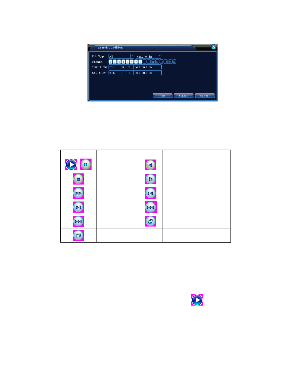
【File searching】Search the file according to the searching parameter.
Picture 3.7 file searching
File type: Set the searching file type.
Channel: Set the searching channel.
Start Time: Set the searching time scan.
【Playback control】Refer to the following sheet for more information.
Button Function Button Function
Play/pause
/
Stop
Fast play
Next frame
Next file
Full screen
Table 3.2 Playback control key
Note: Frame by frame playback is only performed in the pause playback state.
【Operation hint】Display the function of the cursor place.
Special functions:
Backward
Slow play
Previous frame
Previous file
Circulation
Accurate playback:Input time (h/m/s) in the time column and then click play
operate accurate playback according to the searching time.
Local zoom:When the system is in single-window full-screen playback mode, you can drag your mouse in the
screen to select a section and then left click mouse to realize local zoom. You can right click mouse to exit.
button. The system can
Page 15
H.264 Network Digital Video Recorder User Manual
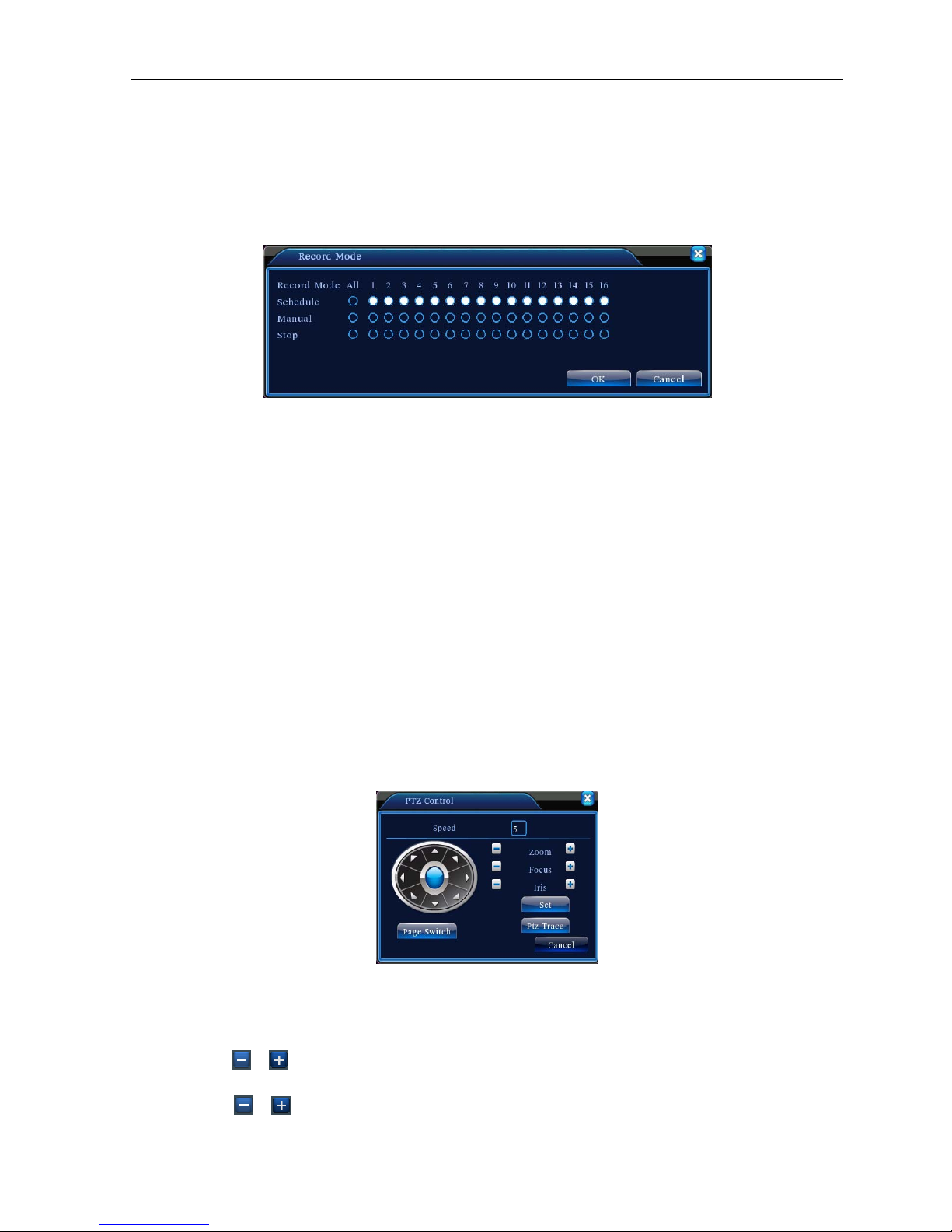
3.5.3 Record Mode
Please check current channel status: “○” means it is not in recording status, “●” means it is in recording
status.
You can use desktop shortcut menu or click [main menu]> [recording function]> [recording set] to enter
the recording control interface.
Picture 3.8 Record Mode
【Schedule】Record according to the configuration.
【Manual】Click the all button and the according channel is recording no matter the channel in any state.
【Stop】Click the stop button and the according channel stops recording no matter the channel in any state.
3.5.4 PTZ control
Operation interface is as followed. The functions include: PTZ direction control, step, zoom, focus, iris, setup
operation, patrol between spots, trail patrol, boundary scan, assistant switch, light switch, level rotation and so
on.
Note1. Decoder A(B)line connects with DVR A(B)line. The connection is right.
2. Click [main menu] >[system configuration] >[PTZ setup] to set the PTZ parameters.
3. The PTZ functions are decided by the PTZ protocols.
Picture 3.10 PTZ setup
【Speed】Set the PTZ rotation range. Default range: 1 ~ 8.
【Zoom】Click
【Focus】Click
/ button to adjust the zoom multiple of the camera.
/ button to adjust the focus of the camera .
Page 16

H.264 Network Digital Video Recorder User Manual
【Iris】Click / button to adjust the iris of the camera.
【Direction control】Control the PTZ rotation. 8 directions control is supportive.(4 directions in Front panel is
supportive )
【High speed PTZ】Full-screen show channel image. Left press mouse and control PTZ to rotate orientation.
Left press mouse and then rotate the mouse to adjust the zoom multiple of the camera.
【Set】Enter the function operation menu.
【Page switch】Switch between different pages.
Special functions:
1.Preset
Set a location for the preset, calls the preset points, PTZ automatically turns to the setting position
1)Preset option
Set a location for the preset, procedure is as follows:
Step1: in Picture 3.10, click the Direction button will turn into preset position, click the Settings button
to enter Picture 3.11.
Step 2: click the Preset button, and then write the preset points in the input blank,
Step 3: click Settings button, return the Picture 3.10 Complete setup
, that is the preset points and preset position corresponds.
Clear Preset:Input preset points, click Remove button, remove the preset。
Preset button
Preset point input blank
Picture 3.11 Preset Settings
2)Preset Point Calls
In Picture 3.10, click Page Shift button, enter PTZ control interface as shown in Picture 3.12. In the input
blank, write the preset points, then click Preset button, PTZ turn to the corresponding preset point.
Page 17

H.264 Network Digital Video Recorder User Manual
Value input blank
Picture 3.12 PTZ Control
2.Cruise between Points
Multiple preset points connected cruise lines, call cruise between points, the PTZ run around on the line
1)Cruise Between Points Settings
Cruise lines is connected by multiple preset points, setting procedure is as follows:
Step1: In Picture 3.10, the Direction key will turn PTZ to designated location , click Settings button to
enter Picture 3.13,
Step 2: click Cruise buttons, the write proper value into the Cruise Line and Preset Points blank,then
click Add Preset Points button, complete setting (also can add and delete cruise line which has been
set up)
Step 3: repeat step1 and step2, until set out all the preset designated cruise lines。
Remove Preset:Please input preset value in the blank, click Remove Preset button, then remove
the preset points.
Remove Cruise Line:Input the number of cruise line, click Remove Cruise Lines button, then
remove the cruise lines set。
Page 18
H.264 Network Digital Video Recorder User Manual
Preset Points Blank
Cruise Button
Cruise Line Blank
Picture 3.13 Cruise Between Points Settings
2)The Calls of Cruise between Points
In Picture 3.10, click Page Shift button, enter PTZ control menu as shown in Picture 3.12. Please input the
number of cruise in the value blank, then click Cruise between Points button, PTZ begins to work on the
cruise line. Click Stop button to stop cruise.
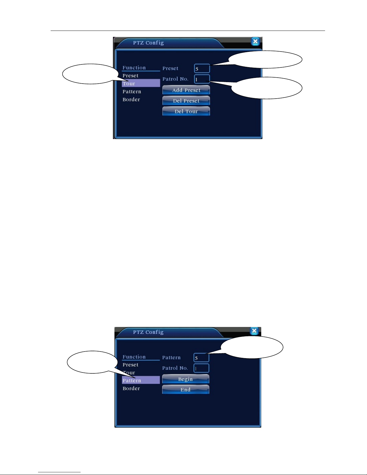
3.Scan
PTZ also can work on the preset scan line repeatedly.
1)Scan setup
Step1:In Picture 3.10, click Setup button ,enter Picture 3.14;
Step2:Click Scan button,the input proper value in the scan value blank;
Step3:Click Start button, enter Picture3.10,here you can set the following items: Zoom. Focus. Aperture.
Direction and so on. Click Setup button to go back Picture 3.14;
Step4:Click End button to complete setup。Click the right button of the mouse to exit.
Scan value blank
Scan Button
Picture 3.14 Scan Setup
Page 19
 Loading...