

Page 1

Dual Streaming
H.264 Multiplex 4CH/8CH Network DVR
Support 3G/3.5G mobile phone/PDA
(Symbian/Windows Mobile/iPhone/iPad/Blackberry/Android)
Support 2xSATA
User Manual
V1.1
Page 2

CAUTION
TO REDUCE THE RISK OF ELECTRIC SHOCK, DO NOT REMOVE COVER.
NO USER SERVICEABLE PARTS INSIDE.
PLEASE REFER SERVICING TO QUALIFIED SERVICE PERSONNEL.
WARNING
TO PREVENT FIRE OR ELECTRIC SHOCK HAZARD, DO NOT EXPOSE THIS
APPLIANCE TO RAIN OR MOISTURE.
NOTE: This equipment has been tested and found to comply with the limits for a
Class “A” digital device, pursuant to Part 15 of the FCC Rules. These limits are
designed to provide reasonable protection against harmful interference when the
equipment is operated in a commercial environment. This equipment generates,
uses and can radiate radio frequency energy and, if not installed and used in
accordance with the instruction manual, may cause harmful interference to radio
communications. Operation of this equipment in a residential area is likely to
cause harmful interference in which case the users will be required to correct the
interference at their own expense.
FCC Caution: To assure continued compliance, use only shielded interface cables
when connecting to computer or peripheral devices. Any changes or
modifications not expressly approved by the party responsible for compliance
could void the user’s authority to operate this equipment.
This Class A digital apparatus meets all the requirements of the Canadian
Interference Causing Equipment Regulations.
- 1 -
Page 3

LIMITATION OF LIABILITY
This users’ manual is supplied ‘as is’, with no warranties, be it expressed or implied, including, but
not limited to, the implied warranties of merchantability, suitability for any exact purpose, or
non-infringement of any third party’s rights.
This publication may include technical inaccuracies or typos. The manufacturer holds the right to
introduce any changes to the information contained herein, for any purpose, including but not
limited to, improvements of the publications and/or related to the product, at any time, without
prior notice.
DISCLAIMER OF WARRANTY
The supplier shall not be liable to any party or any person, except for replacement or reasonable
maintenance of this product, for the cases, included but not limited to the following:
Any damage or loss, including but not limited to: direct/indirect, consequential, special, exemplary
use arising out of or related to the product;
Inappropriate use or negligence of the user in operation of the product, resulting in personal injury
or any damage;
Unauthorized disassembly, repair or modification of the product by the user;
Any problems or consequential inconvenience, loss or damage, caused by connecting this product
to devices of the third parties;
Any claim or action for damages, brought by any photogenic subject, be it a person or organization,
due to violation of privacy whereby the surveillance picture and/or saved data becomes public or is
used for the purpose other than surveillance.
- 2 -
Page 4

PRECAUTIONS
Please refer all work related to the installation of this product to qualified service personnel or system
installers.
Do not operate the appliance beyond its specified temperature, humidity or power source ratings.
Use the appliance at temperatures between 0
input power source for this appliance is between 90 ~ 264 VAC, 47 ~ 63 Hz. Performance and lifetime of
hard disk drives are easily affected by heat (used at high temperature). It is recommended to use this
appliance at temperature between +20
o
C ~ +30oC (68oF ~ 86oF)
Handle the hard disk drives with care. It is possible to damage them if they are moved while their motors
are still running. Do not move them just after turning the power on or off (for around 30 seconds). Protect
the hard disk drives from static electricity. Do not stack them or keep them upright. Do not use an electric
screwdriver to fix them.
Clean only with dry cloth.
Do not block any ventilation openings.
Do not use the appliance near any heat sources such as radiators, heat registers, stoves or other apparatus
that produce heat. .Protect the power cord from being stepped on or pinched particularly at plugs,
convenient receptacles and the points where they exit from the apparatus. .Do not drop metallic parts
through slots. This could permanently damage the appliance. Turn the power off immediately and contact
qualified service personnel for service. .Handle the appliance with care. Do not strike or shake, as this may
damage the appliance.
Do not expose the appliance to water or moisture, nor try to operate it in wet areas. Do take immediate
action if the appliance becomes wet. Turn the power off and refer servicing to qualified service personnel.
Moisture may damage the appliance and also cause electric shock.
Do not use strong or abrasive detergents when cleaning the appliance body. When the dirt is hard to
remove, use a mild detergent and wipe gently. .Do not overload outlets and extension cords as this may
result in a risk of fire or electric shock. .Please make a note of your settings and save them. This will help
when you are required to change the system configuration, or when unexpected failure or trouble occurs.
Distributing, copying, disassembling, reverse compiling, reverse engineering, and also exporting in
violation of export laws of the software provided with this product, is expressly prohibited.
o
C ~ +45oC (32oF ~ 113oF) and humidity below 85%. The
- 3 -
Page 5

INDEX
1. STAR TING ............................... ............................................. .......................................... .............................................. - 5 -
PLEASE REFER TO THE MANUAL INSIDE THE CD FOR DETAILS, THE HARD COPY IS ONLY FOR
REFERENCE .......................................................................................................................................................................... - 5 -
1.2 WHAT ARE INSIDE THIS DVR PACKAGE? ........................................................................................................ - 5 -
1.3 STARTING THIS DVR ................................................................................................................................................. - 5 -
1.3.1 BEFORE TURNING ON THE DVR .......................................................................................................................... - 5 -
1.3.2 DVR local Setup ............................ .............................. ............................ ............................. ........................... - 5 -
FRONT PANEL ...................................................................................................................................................................... - 8 -
BACK PANEL ...................................................................................................................................................................... - 10 -
2.3 REMOTE CONTROLLER .............................................................................................................................................. - 10 -
3. HARDWARE INSTALLATION ................................................... ... .. .. ..... .. ... .... ... .. .. ..... .. ... .... ... .. ... .. .............................. - 11 -
3.1 BASIC CONNECTIONS .................................................................................................................................................. - 11 -
3.2 HARD DISK AND INTERNAL DVD BURNER INSTALL ................................................................................................. - 11 -
3.3 PTZ CONTROL CONNECTIONS ................................................................................................................................... - 12 -
4. POWER-ON DVR AND QUICK START .............. .. ... .... ... .. ... .... ... .. ..... .. .. ... .... ... .. ..... .. .. ... .... ... .. ..... .. ... .. ....................... - 12 -
4.1 LIVE VIEW SCREEN (STATUS BAR) ............................................................................................................................ - 13 -
4.2 MAIN MENU(TOOLS BAR) .......................................................................................................................................... - 14 -
4.3 FORMAT HDD ............................................................................................................................................................. - 14 -
4.4 VIDEO RECORD ........................................................................................................................................................... - 15 -
4.5 VIDEO PLAYBACK ....................................................................................................................................................... - 16 -
4.6 VIDEO BACKUP ............................................................................................................................................................ - 18 -
4.7 PLAY BACKUP VIDEO ON PC ...................................................................................................................................... - 19 -
4.8 PTZ CONTROL ............................................................................................................................................................ - 20 -
5. DVR SETTING ..................................................... ... .. ..... .. ... .. ..... .. .. ..... .. ... .. ..... .. .. ..... .. ... .......................................... ......... - 22 -
5.1 MENU TREE & OPERATE ............................................................................................................................................ - 22 -
5.2 SYSTEM SETTING ........................................................................................................................................................ - 23 -
5.2.1 Language ............................................................................................................................................................. - 23 -
5.2.6 Password Setting and what if forgotten ............................................................................................................. - 24 -
5.2.8 Create/Delete User Account, assign authorities, setup SEQ Display(Preview Cruise) and Lock Cameras: - 24 -
5.2.9 Resource Management .................................. ........................................... .......................................... ................ - 26 -
5.3 RECORD SETTING ....................................................................................................................................................... - 28 -
5.3.3 Vide o Quality ....................................................................................................................................................... - 29 -
5.3.6 OSD Setting ......................................................................................................................................................... - 29 -
5.3.7 Record Resolution ............................................................................................................................................... - 30 -
5.3.8 Dual Str e aming for Network(Record-Advanced Setting) ................................................................................. - 30 -
5.4.1 Camera Channel ................................................................................................................................................. - 31 -
5.4.6 Motion Detection Setting .................................................................................................................................... - 31 -
5.4.7 Privacy Mask(Mosaic) ........................................................................................................................................ - 31 -
5.4.8 Motion, Video Lost and Channel Name(Video- Advanced Setting) ................................................................ - 32 -
5.5 NET SETTING ............................................................................................................................................................... - 33 -
5.5.1 Network (Static IP/DHCP) ........................ ............................................... ................................................. ......... - 33 -
5.5.6 Email Server set u p for Email notify ................................................ ................................................................. - 35 -
5.5.7 UPnP and Mobile por t( 3 rd p age in Ne t Se tting) ....................................... ...................................................... - 36 -
5.6.2 Alarm Input Type ............. ............................................. .......................................... ............................................ - 38 -
5.6.3 Event Handling ......... .................................................... ...................................................... ................................ - 38 -
5.6.4 Alarm Setting( S ch edule), Zoom Out and Hard Disk Full actions .................................................................. - 39 -
5.7.1 Log View ............................. ........................................ ........................................... ..................................... ......... - 40 -
5.7.2 Software Upgrade ............................... ....... .... ..... ..... ....... ..... .... ....... ..... ..... ....... .... ..... ..... ....... ..... .... ..... ................ - 40 -
5.7.4 HDD Capacity Show DVR current HDD
capacity status. .................................... ..... .. ... .. ..... .. ... .. ..... .. .. ... .. ..... .. .. ... .... ... .. .. ..... .. ... .. ................................................. - 41 -
6. WEB BROWSER OPERATION(IE BROWSER ONL Y ) ........................................................................... ................ - 42 -
6.1 ENABLE DOWNLOAD UN-SINGED ACTIVEX CONTROL IF NECESSARY .................................................................... - 42 -
6.5 DEVICE PARAMETERS SETTINGS ............................................................................................................................... - 44 -
6.6 VIDEO FILES PLAYBACK & DOWNLOAD ................................................................................................................... - 48 -
- 4 -
Page 6

6.6.1 Video Files Playback ........................................................................................................................................... - 48 -
6.6.2 Download Video Files ......................................................................................................................................... - 49 -
6.6.3 Device Log .................................................................................................................................... ....................... - 49 -
6.6.4 W a ter Mark Verification ......................... ...................................... ........................................ .............................. - 50 -
6.7 CHANNELS ALLOCA TION IN CAMERA VIEW WINDOW ............................................................................................... - 50 -
7. 3G/3.5G MOBILE PHONE/PDA SUPPORT ................................................................................................................ - 50 -
7.1 WINDOWS MOBILE ..................................................................................................................................................... - 51 -
7.2 NOKIA/SAMSUNG/LG SYMBIAN S60 3RD/S60 5
7. 3 IPHONE/IPAD SERIES ............................................................................................................................................... - 54 -
7. 4 BLACKBERRY SERIES ................................................................................................................................................. - 55 -
7. 5 ANDROID MOBILE (GOOGLE PHONE COMPATIBLE) ................................................................................................ - 58 -
8. APPENDIX .... ........................ ..................... ....................... ..................... ..................... ...................................................... - 60 -
APPENDIX A-HDD CAPACITY/RECORDING TIME ESTIMATE ........................................................................................ - 60 -
APPENDIX B– COMPATIBLE HDD LIST ........................................................................................................................... - 61 -
APPENDIX C– COMPATIBLE USB PORTABLE DVD BURNER LIST ................................................................................. - 61 -
APPENDIX D– CHANGE NOTICE ....................................................................................................................................... - 61 -
TH
PHONES ........................................................................................ - 51 -
1. Starting
1.1 Quick Reference to Start this DVR and Change Notice
Please Refer to the Manual inside the CD for details, the hard copy is only for reference
1.2 What are inside this DVR package?
Please refer to Appendix E-
What are inside this DVR inside this manual.
Change Notice
Please refer to Appendix F– Change Notice for details.
1.3 Starting this DVR
1.3.1 Before Turning on the DVR
Please install SATA HDD or DVDRW in the Hard Disk Tray. (Chapter 3.2 and Appendix B)
Please refer to Chapter 3 for all connections.
To use the remote controller (Chapter 2.3
)
1.3.2 DVR local Setup
Please wait for about 40 seconds for the system to start up.
Please login the system (Chapter 4
(Please note that the HDDs cannot be used for recording if they are not formatted yet.)
Please refer to Chapter 4
Please refer to Chapter 5.2
Time & Language.
Please refer to Chapter 4.4
for all basic operations.
to setup the system correctly, esp. for NTSC/PAL, Record Resolution,
and Chapter 5.3 for recording setting.
), and then physically format the HDDs (Chapter 4.3).
- 5 -
Page 7

Please refer to Chapter 4.5, Chapter 4.6, Chapter 4.7 to search, playback, and archive the
recorded video/audio.
Please refer to Chapter 5.4.6
Mask(Mosaic), and Chapter 5.6
Please refer to Chapter 3.3
and control the PTZ cameras correctly.
Please refer to Chapter 5.5
DDNS and E-mail Server
Please refer to Chapter 6
Please refer to Chapter 7
Please refer to Appendix A
Please refer to Appendix B
Burner List
for remote access via internet or intranet from PC/Laptop
for remote access via internet or intranet from mobile phone
/5.4.8 for motion Detection, Chapter 5.4.7 for Privacy
for Alarm setting
for PTZ camera connection, Chapter 4.8 and Chapter 5.4 to set up
for Network Setting including DHCP/Static IP/PPPoE, ports no.,
for the estimated recording time.
and Appendix C for the compatible HDD/USB portable DVD
1.3.3 DVR Network Setup and Web Browser
Please note that the user must have system administrator authority for the client PC, please refer
to Chapter 6
If upgraded this DVR for new version software, it is better to delete some components from
These DVRs have mobile player software for 3G/3.5G mobile phone/PDA(Windows
Mobile/iPhone/Nokia/Blackberrry), please refer to Chapter 7. 3G/3.5G Mobile Phone/PDA Support
for more details
for details
the PC by the batch command file “WebOcxClean.dat” inside the CD root, please close IE
before run this batch command file.
Login/Logout the System
Logout : MENU(Setting) →SAVE→ Logout
Login: Power on or after Logout
1.2 Setup the System
Format HDD: MENU (Setting) → <Maintenance> → <HDD Manage>→Click〖>>〗→【Formatting
】to start HDD format.
Change Language, Time, NTSC/PAL, Record Resolution, Password, User Auority : MENU(Setting)
→<System>
Setup PTZ: MENU (Setting) →<Camera>
Setup Network: MENU(Setting) →<Net> →<Network> Static IP/DHCP, or MENU(Setting)
→<Net> →<Next Page> for PPPoE/DDNS
Change Network Port: MENU(Setting) →<Net> →<Network> for Http/Command/Media Ports,
MENU(Setting) →<Net> →<Next Page> for Mobile Port
Set up E-mail Server:MENU(Setting) →<Net> →<Network>
→<Next Page>→<Next Page>
Basic Operations
Change Split Window : CH1 ~ Ch4 / , or 1 ~ 8/ in the remote control
Move Focus : ▲, ▼, ◄, ►
Search/Playback/Backup :
Video playback and Chapter 4.6
1.2.1 Remote Access -> Before Logging On
User’s computer need download ActiveX components for web access at the first time connect to DVR. If
user’s Internet explorer prohibits the download action then please manually enable the download of
un-signed ActiveX in IE.
Download unsigned ActiveX controls Enable or Prompt
Initialized and script ActiveX controls not marked as safe Æ Enable or Prompt
If has upgraded this DVR for new version software, it is better to delete some components from the
C:\WINDOWS\system32 of PC used to remote access this DVR by the batch command file
“WebOcxClean.dat” inside the CD:\Multiplex H264 DVR Utility, please close IE before run this batch
command file.
for faceplate/remote control, and for OSD, please refer to Chapter 4.5
Video Backup
- 6 -
Page 8

1.2.2 Remote Access -> IE Operations
R
R
Please note that the PC user must have system administrator password for the PC; otherwise, the process
will fail, and an error dialog will be shown. For the Windows 7/Vista, please turn off the UAC function –
Chapter 6.2 Turn off UAC for Windows 7 and Vista
http://technet.microsoft.com/en-us/library/cc709691.aspx
Please refer to Chapter 6
1.2.3 Remote Access -> Mobile Player
These DVRs have mobile player software for 3G/3.5G mobile phone/PDA(Windows
Mobile/iPhone/Nokia/Blackberrry), please refer to 7. 3G/3.5G Mobile Phone/PDA Support
details.
For limited upload bandwidth of internet that DVRs connect, or limited streaming capability of some
mobile phone/PDA, you have to adjust bandwidth of DVR to internet, please refer to 5.3.8 Dual
Streaming for Network (Record- Advanced Setting) or 6.4 Device Parameters Settings - Channel
Camera setting, Sub Bitstream, Subcode
for details
(from IE) for more details
, and source info:
for more
2 . Product Overview:
2.1 Product Features
Model 4CH DV
Video Format
Video Compression
Video Input
Video Main Output
Audio Compression
Record Resolution &
Frame rate
Playback resolution &
Frame Rate
PAL:CIF @ 100FPS/352×288
Half D1 @50FPS/704x288
D1 @25FPS/704x576
NTSC:CIF@ 120FPS/352×240
Half D1 @60FPS/704x240
D1@ 30FPS/704x480
PAL :CIF 100FPS/352×288 NTSC:CIF 120FPS/352×240
Half D1 50FPS/704x288 Half D1 60FPS/704x240
D1 25FPS/704x576 D1 30FPS/704x480
4 Channel 8 Channel
BNC x 1 and VGA maximum 1920 x 1080 resolution
8CH DV
NTSC/PAL
H.264
ADPCM
PAL:CIF@ 200FPS/352×288
Half D1@100FPS/704x288
D1@50FPS/704x576
NTSC: CIF@240FPS/352×240
Half D1@120FPS/704x240
D1@60FPS/704x480
1CH/4CH
Audio IN/ Out
Record Mode
Continuous / Schedule/Alarm / Motion Detect, Individual channel schedule
recording setup
RCA 4 Input / 1 Output RCA 8 Input / 1 Output
- 7 -
Page 9
Storage Capacity
)
)
1 or 2 SATA Interface (2TB/4TB)
Alarm
Network
Network Function
USB 2.0 Interface
Playback method
RS485/PTZ
PTZ Protocol
Video Backup
Power
Operating T emperatur e
Dimension
Model
4 Inputs, 1 Output (NC, NO relay
RJ-45 10/ 100 Base T Ethernet connector (PPPoE, DHCP, DDNS, Static IP),
UPnP and FTP
IE Browser Live Monitor, Configuration, Download Video, Playback, and
Mobile Phone Surveillance
Mouse/Potable Mobile HDD/Flash Drive/DVD Burner/Firmware Upgrade
Normal Play, Fast Forward, Backward, Single Step
1 x RS485
PELCO-P , PELCO-D, Samsung, Panasonic, Philips etc.
AVI, MPEG4 or H.264 Raw for USB Flash Disk
DC12V/3.3A or 5A(optional for 2 SATA)
O’C ~ +40-C
315(W) x 224(D )x 52(H) mm
SP3278B-KW3278C (1XHDD)
SP3279B-KW3279C (2XHDD
315(W) x 224 (D) x 52 (H) mm or
436(W) x 339(D) x 55(H)
KW3274B-KW3274C(1XHDD)
KW3275B-KW3275C(2XHDD
2.2 Panels and Remote Controller
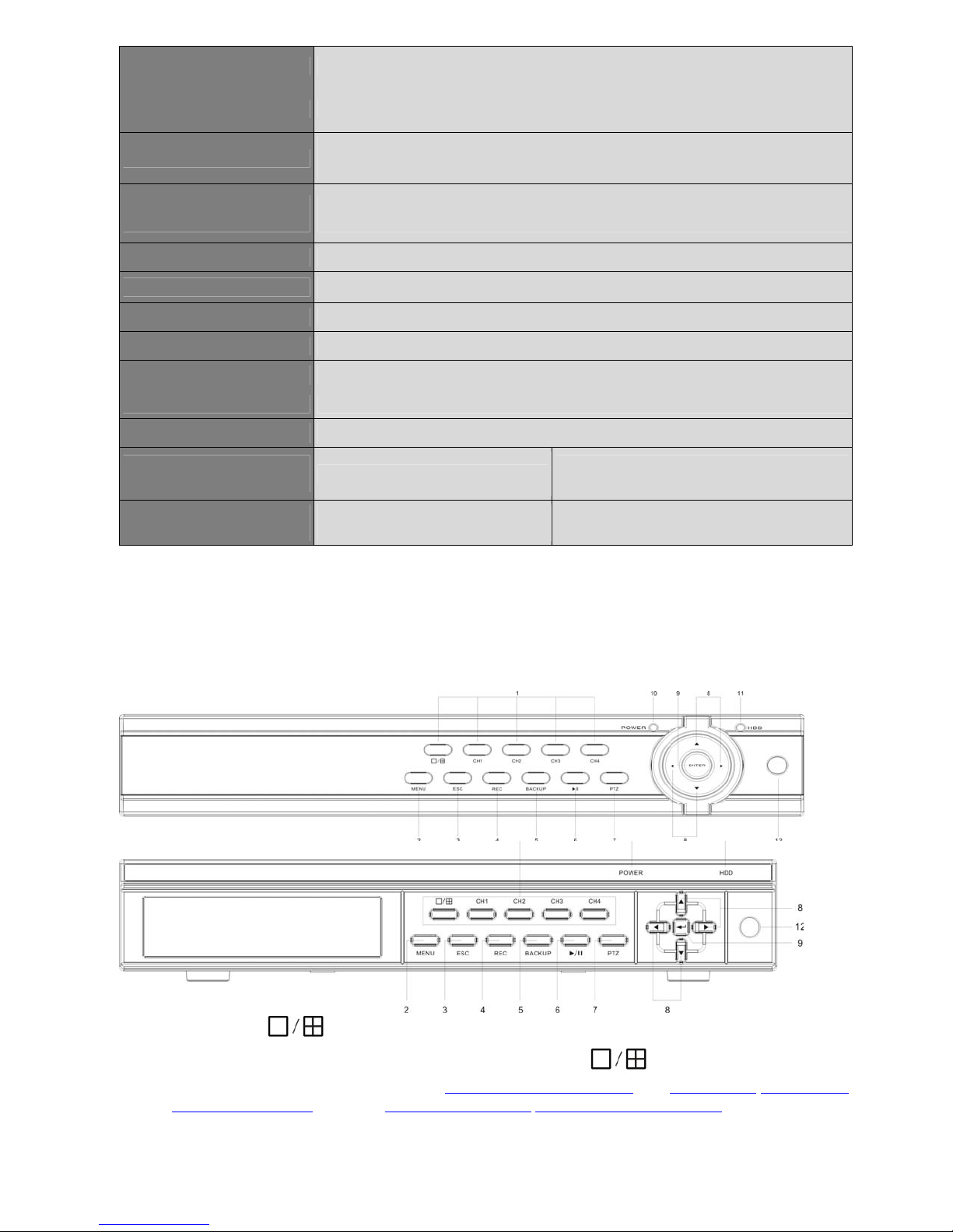
Front Panel
Please take actual front panel as quasi-:
4CH DVR
1. CH1 ~ Ch4 /
Direct switch to single camera window or 4 camera windows
playback or back up in schedule record(Chapter 4.5 Video Playback
Mask setting(Mosaic) setting, or 5.3.2 Record Schedule/5.6.4 Alarm Schedule setting
- 8 -
Start and Stop time setting of
), or 5.4.6 Motion/5.4.7 Privacy
Page 10
2. MENU: Press this button to display the main menu.
3. ESC: Exit window or switch the tool bar(main menu) and status bar
4. REC: Start or Stop manual record function.
5. Backup: Open video search and backup menu
6. Play/Pause (
7. PTZ: Open camera selected with PTZ operation menu.
): Open video search and playback menu. press to pause playback.
8.
9. Enter: Confirm operation.
10. Power LED
11. HDD LED
12. IR Window
, , , : Arrow Buttons. Press , to move to selection box, press , to select
submenu parameters.
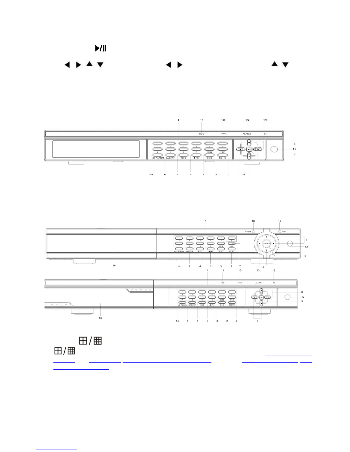
8CH DVR(1 x SATA or 2 x SATA)
8CH DVR(2 SATA HDD, with DVDRW or HDD removable Rack)
Key buttons 2 ~ 12 are same as 4CH DVR, except:
1. 1~8 /
Start and Stop time setting of playback or back up in schedule record(Chapter 4.5 Video
Playback), or 5.4.6 Motion/5.4.7 Privacy Mask setting(Mosaic) setting, or 5.3.2 Record Schedule/5.6.4
Alarm Schedule setting
13. ALARM LED: indicate alarm happened
14. NO ALARM: Cancel Alarm and Buzzer
15. IR LED
16. DVD Burner or Removable HDD Cover
Direct switch to single channel window , or 9 camera windows.
8CH DVR(1 x SATA or 2 x SATA) with complex key combination
- 9 -
Page 11
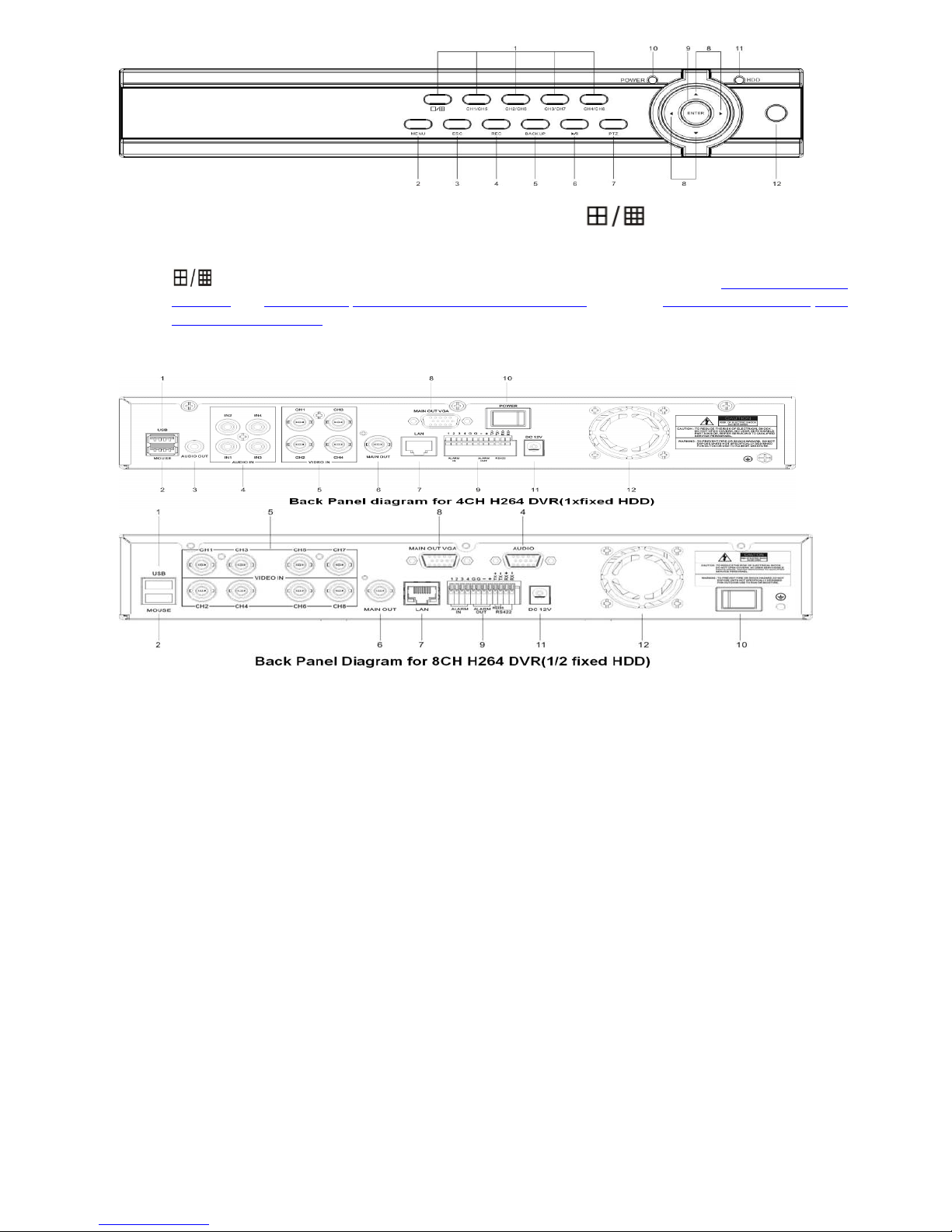
Key buttons 2 ~ 12 are same as 4CH DVR, except:
1. Complex keys - CH1/CH5, CH2/CH6, CH3/CH7, CH4/CH8,
Channel 1/Channel 5, Channel 2/Channel6, Channel 3/Channle 7, Channel 4/Channel 8 toggle switch
button, and also button switch between 1/9 camera windows
Start and Stop time setting of playback or back up in schedule record(Chapter 4.5 Video
Playback), or 5.4.6 Motion/5.4.7 Privacy Mask setting(Mosaic) setting, or 5.3.2 Record Schedule/5.6.4
Alarm Schedule setting
Back Panel
1. USB connector: Connect backup devices like flash drive, portable HDD or DVD burner
2. Mouse Connector: Connect USB mouse.
3. Audio Output Connectors: 1 channel audio output, RCA (2Vp-p,600Ω) for 4CH DVR
4. Audio Input Connectors (AUDIO IN 1-4/1-8): 4 channel audio input, RCA (2Vp-p,600Ω) for 4CH
H264 DVR; or connector for 8CH H264 DVR to connect Audio cable(8CH Audio Input+ 1CH Audio
Output)
5. Video Input Connectors (1-4/1-8): 4 or 8 channel video input, BNC (1Vp-p,75Ω)
6. Video Main Output Connector: DVR system screen output, BNC (1Vp-p,75Ω)
7. Ethernet Connector: RJ-45 10/100 Base-T Ethernet network.
8. VGA Connector (optional for 4CH): Connect VGA/LCD monitor
9. Alarm Input Connectors (ALARM IN 1-4, 5-6 Ground): Connect to external sensor device
Alarm Output Connectors (ALARM OUT 7-8):Connect to external sensor device
RS-422 Connector (9-12): RS-485 Connector (9-10, TX+, TX-) Support PTZ camera control
10. Power Switch
11. Power Input Socket (12V DC)
12. Fan
2.3 Remote Controller
The remote controller is an accessory to ease the user’s operations. You can do all the operations by the
remote controller instead of the buttons on the front panel.
- 10 -
Page 12
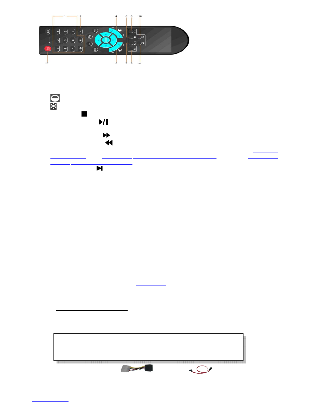
1. Alpha-numeric Buttons (1-9, 0, 10+):Press these buttons for camera selection in most circumstances.
These buttons can also be used to enter text and number
2. DEL Button (DEL): In text editing mode, this button is used as “del” key.
3. Alarm Reset Button: Press this button to cancel alarm activation; click this button will pop a message to
show the present alarm information.
4.
5.
6. Stop Button (
7. Play/Pause Button (
8. Fast Forward Button (
9. Fast Backward Button (
10. Function Key(FN): Start time and Stop time setting of playback or back up in schedule record(Chapter 4.5
11. Single Step Button (
The Other Buttons: Each of the other buttons corresponds to one of those buttons on the front panel. Please
refer to the descriptions in Section 2.1.
Contrast Button: Adjust image contrast up(+)/down(-).
Brightness Button: Adjust image brightness up(+)/down(-).
): Press this button to stop the playback.
): Press this button to search and play the recorded images, or pause the
playback.
): Press this button for fast forward playback.
): Press this button for fast backward playback.
Video Playback), or 5.4.6 Motion/5.4.7 Privacy Mask setting(Mosaic) setting, or 5.3.2 Record
Schedule/5.6.4 Alarm Schedule setting
):Press this button to play the recorded images frame by frame.
Front Panel
3. Hardware Installation
3.1 Basic Connections
Cameras: Connect the camera output to video input connector in real panel of the DVR.
The video input interface is standard BNC connector, 1Vp-p, 75 Ω.
Audio Connector: The audio input interface is standard RCA socket, 2Vp-p, 600 Ω.
The audio input resistance is a little bit high; please use active sound collection device or active
microphone. And the audio signal cable should keep away from the interference of strong
electromagnetism and electric field.
Monitor: Connect the main output connector to a monitor. Use BNC-to-RCA connector to
work with Audio/Video RCA cable.
Power: Use adapter come along with DVR, plug 12V
socket.
Alarm Input/output: Please refer to Chapter 5.6.2.
Ethernet: Connect the Ethernet connector to a standard twisted-pair Ethernet cable for remote access
via LAN or internet
USB 2.0 : Support Mouse, USB Flash Drive, USB portable HDD, USB portable DVD Burner.
Only support FAT32 file system
.
output connector into the power
DC
3.2 Hard Disk and internal DVD Burner Install
HDD must be formatted by DVR system before it can be used to record.
PS. Do not format HDD by PC, it will cause incompatibility.
Please refer to Section 4.3 Format HDD
to format the HDD.
There are usually power cable and data cable with the DVD Burner you buy,
- 11 -
Page 13
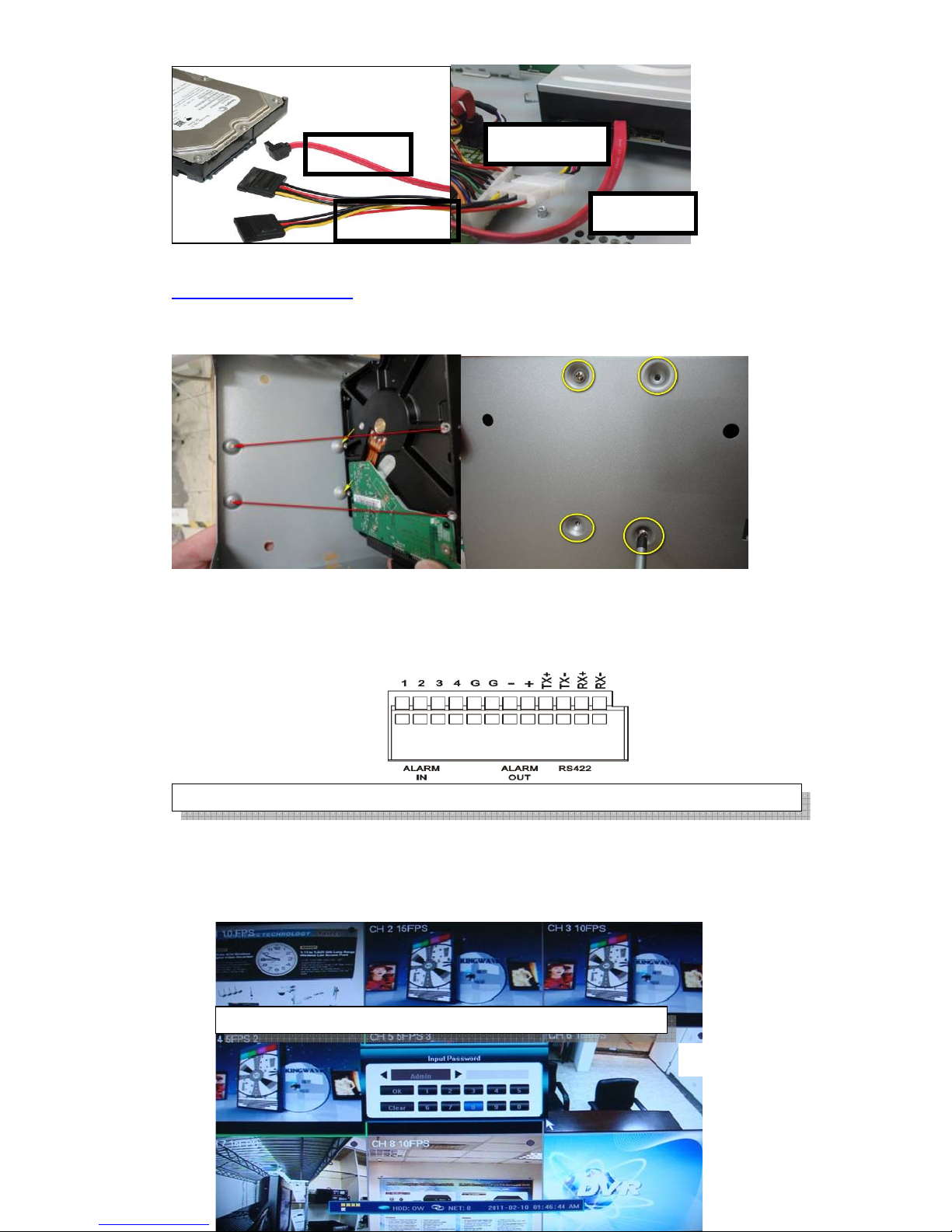
connect to our DVR as follows(right):
password o
[888888]
Use
[666666]
Data Cable
Power Cable
Internal DVD Burner message appears only in Video Backup with MPEG4 format, please refer to
Chapter 4.6 Video Backup
For the internal fixed HDD installation, there is no HDD bay for it, there are 4 screw holes underneath
housing bottoms, where you can secure them as below:
Power Cable
Data Cable
3.3 PTZ Control Connections
Connect the PTZ control interface to RS485 TX+ and TX- interfaces of rear panel.
~
4. Power-on DVR and Quick Start
Power-on the DVR and wait for system program loading. The DVR will buzz and “NO Hard Disk” appears
when no hard disk installed in DVR. This DVR has dual display(TV/VGA monitor), but OSD control is
only side, default is VGA, you may press “ESC” + “1” +”ESC” continuously from faceplate or remote
control to switch to TV mode
First window will request
to select user account
and password to operate
DVR system.
Default
f Admin is
r is
- 12 -
Page 14
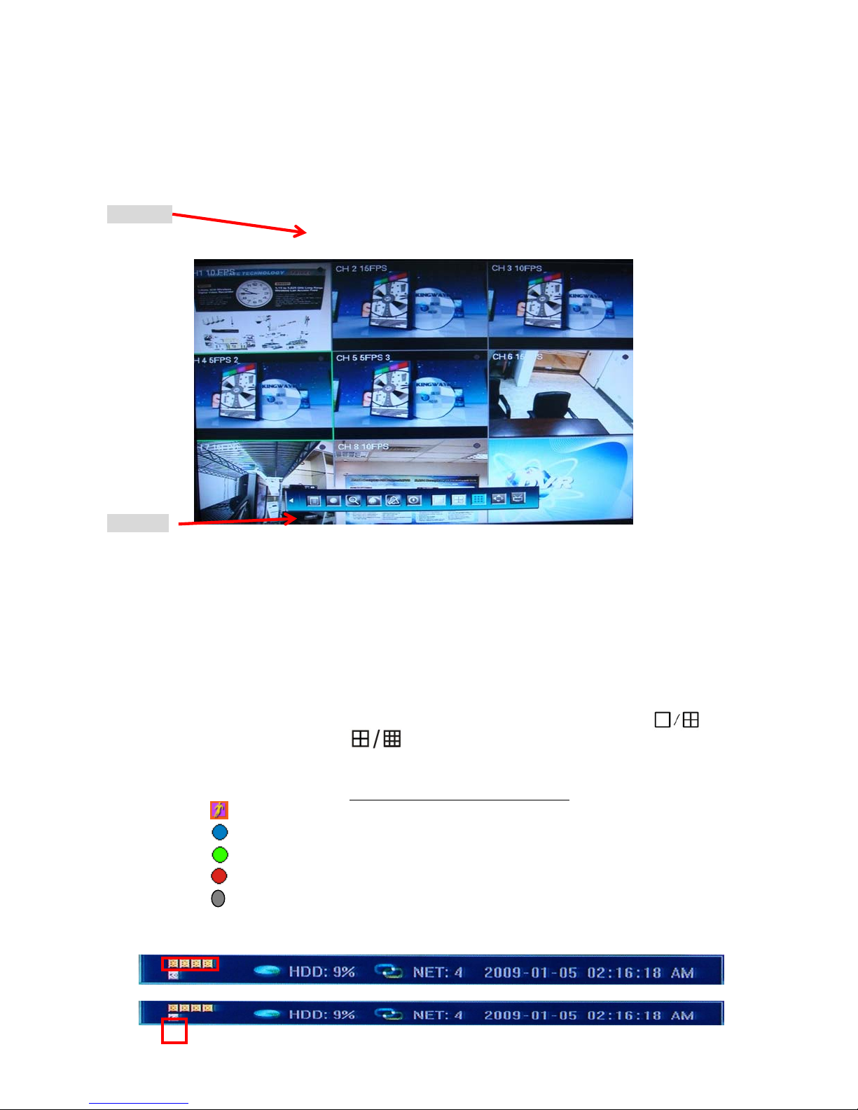
Status Bar
Tools Bar
DVR system status bar at the bottom of the screen. Right-click mouse key or press 【Enter】at front panel will
open【Tools Bar】for system setting and operating.
4.1 Live View Screen (Status Bar)
Single Channel display: When in 4/9 split view modes, the window with highlight green border is
the current selected one. User can use mouse or press 【Direction】 buttons to switch to another channel.
If the audio output device is connected, the audio can also be monitor together with video. User can
select to display a single particular channel by pressing the corresponding
【Numbers】buttons 1~8. When in single split view mode, user can enter into 4/9
splits view mode by pressing or
Channel Status Display: Indication of “motion detection” / “common recording” / “alarm recording”
and etc. will be displayed on the right upper corner of each split screen
Indicates “motion detection”.
Blue indicates “common recording”
Green indicates “motion detection triggered recording”
Red indicates “alarm triggered recording”
Grey indicates “manual recording”
Peripheral alarm input / alarm output/HDD/Network display : Indication will be displayed on
system status bar:
button directly, or reverse.
. The details are as follows:
The four icons (4/8CH) indicate the alarm input status. When happened, it changes into red color.
- 13 -
Page 15
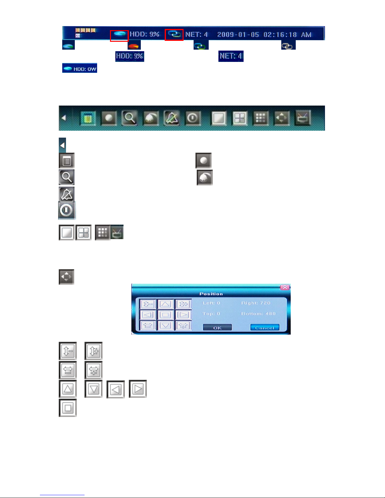
The The last icon (4/8CH) indicates alarm output. When happened, it changes into red color.
HDD normal(blue) HDD Failure(red) Network connected(blue) Network
disconnected(gray)
Hard Disk Overwrite
HDD percentage recorded No. of cameras network connected
4.2 Main Menu(Tools Bar)
Right click mouse or press 【Enter】 button in preview mode, the Tool Bar shown as below will appear:
: Hide the tool bar.
: System configuration : Manual record
:: Search, playback and backup record files
:: Cancel alarm notification. Click this button will pop a message to show the present alarm
information.
Shut down the system before power off, good for HDD protection
To switch screen display mode “Single camera” Æ “Quad 4 camera” Æ”9
camera”
To switch the OSD control between TV and VGA monitor, also can be done by pressing
“ESC” + “1” +”ESC” continuously from faceplate or remote control
:To adjust the screen, 8 pixels per unit can be adjusted as follows:
: PTZ operation
:To reduce or increase screen in vertical direction.
:To reduce or increase screen in horizontal direction.
:To zoom out the screen to largest and show in central.
4.3 Format HDD
Login DVR system as【Admin】account.
Select <Tool Bar> → <Setting> → <Maintenance> → <HDD Manage> item. Click〖>>〗to open HDD
Mange window.
:To move the screen up, down, left, right
- 14 -
Page 16
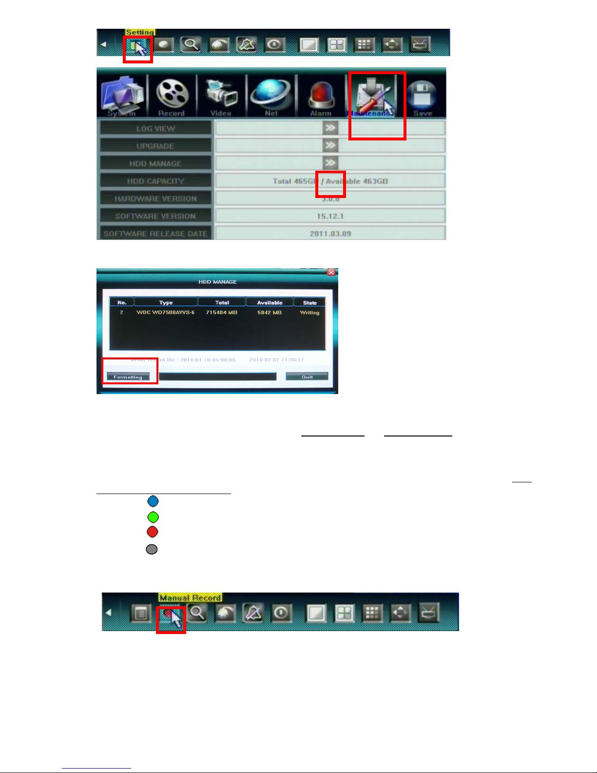
HDD information will display on the windows if DVR detection HDD correctly. Click 【Formatting】to
start HDD format.
4.4 Video Record
There are two methods to precede record in DVR, manual record and schedule record.
The priority of manual record is higher than schedule. If the record schedule is conflict with manual
record, the manual record will be processed firstly until the manual record being canceled. Record types
include “common recording” / “alarm triggered recording” / “motion detection triggered recording” /
“alarm & motion detection triggered recording”, the following indications will be displayed on the right
upper corner of each split screen:
Blue indicates “common recording”
Green indicates “motion detection triggered recording”
Red indicates “alarm triggered recording”
Grey indicates “manual recording”
Manual Record
Please select <Tool Bar>→<Manual Record> to let the specific channel record or not. Press【●】
button to start/stop recording manually.
- 15 -
Page 17
The video recorded manually is named “common recording”
Schedule Record
Please select <Tool Bar> → < Setting > → <Record> → < Record Schedule> to set.
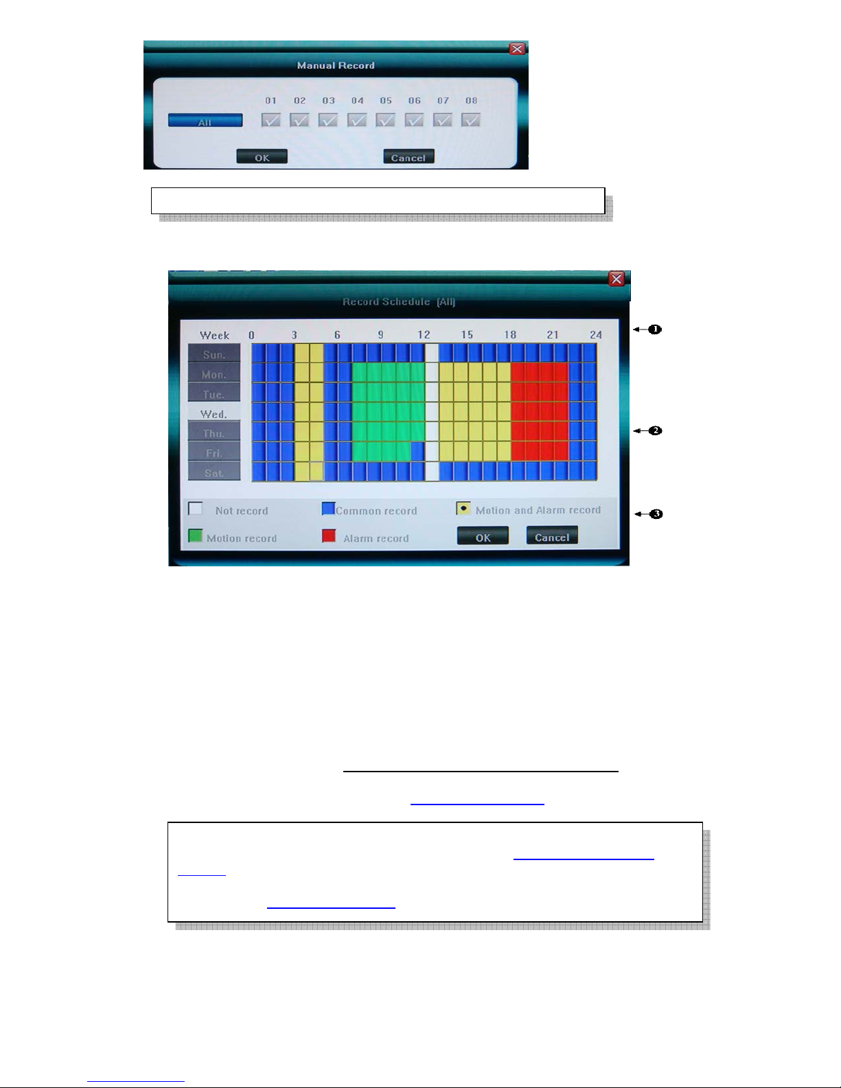
The setting screen is shown as the figure below:
①. The current recording channel number
②. The record schedule
③. Description of record type
System provides a recording option for 24 hours every day and Sunday through Saturday every week.
Unit is hour. One grid indicates one hour.
Move highlight icon to a time grid using 【Direction】 buttons.
Specify the recording type by repeat pressing 【Enter】 button or double left clicking mouse,(the color
of the grid will change relevantly).
Select OK to confirm settings. The settings will take effect after being saved.
For the detailed operations, please refer to 5.3.2 Record Schedule
When motion detection & alarm recording is selected, the motion detection
sensitivity and area should be set ahead. Please refer to 5.4.6 Motion Detection
Settings for details.
When alarm recording is selected, the alarm triggering settings should be set ahead.
Please refer to 5.6.3 Event Handling
4.5 Video Playback
Specify the date/time and channel number by selecting <Tool Bar>→<Record Search>.
The searching results will be list on the screen in responding different colors so as to distinguish different
for details.
- 16 -
Page 18
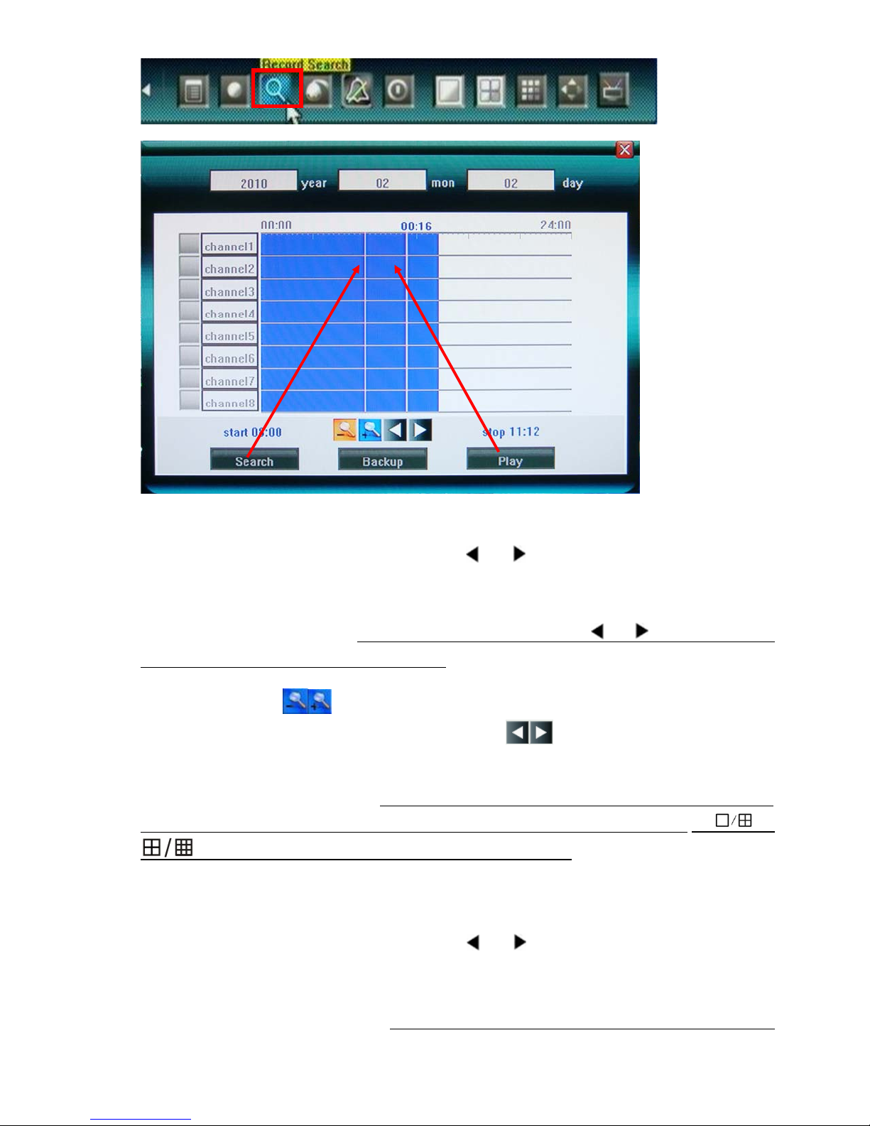
record types.
Date & time search by Panel or remote control
In order to playback a certain video feed from a particular camera, you first need to indicate what time and
which camera you wish to receive this information from.
Move highlight icon to relevant selection box using 【
】,【 】buttons.
Move highlight icon to date/time selection box, modify time using 【▲】,【▼】 buttons. Move highlight
icon to channel selection box, press【Enter】 button to select it or cancel selection.
After setting time, channel number , move highlight icon to Search using 【
】,【 】 buttons, and press
【Enter】 button to start searching recorded video.
Move highlight icon to
If the timeline is out of screen, please move highlight icon to
, press 【Enter】 button to zoom in/zoom out timeline.
and press 【Enter】 button to
display the part out of screen.
After searching over, by remote control, press【FN】button will move to timeline to select start time, then
press 【FN】button again to select stop time, after that, press【FN】button to finish the setup; by or
button of faceplate to select start/stop time as【FN】above..
The available recordings will be represented by differently colored bars on the time line depending on the
type of the recording (Blue: common recording, Green: motion detection triggered recording, Red: alarm
triggered recording, Grey: manually made recording).
After all settings, move highlight icon to Play using 【
】,【 】 buttons, and press 【Enter】button to
start playing.
Date & time search by Mouse
User can mouse click to specify time. First left-click on timeline will mark 【start time】and there will
- 17 -
Page 19
have a vertical line show up , second left-click will mark 【stop time】. Mouse right-click will clear all
marked time.
Playback Control
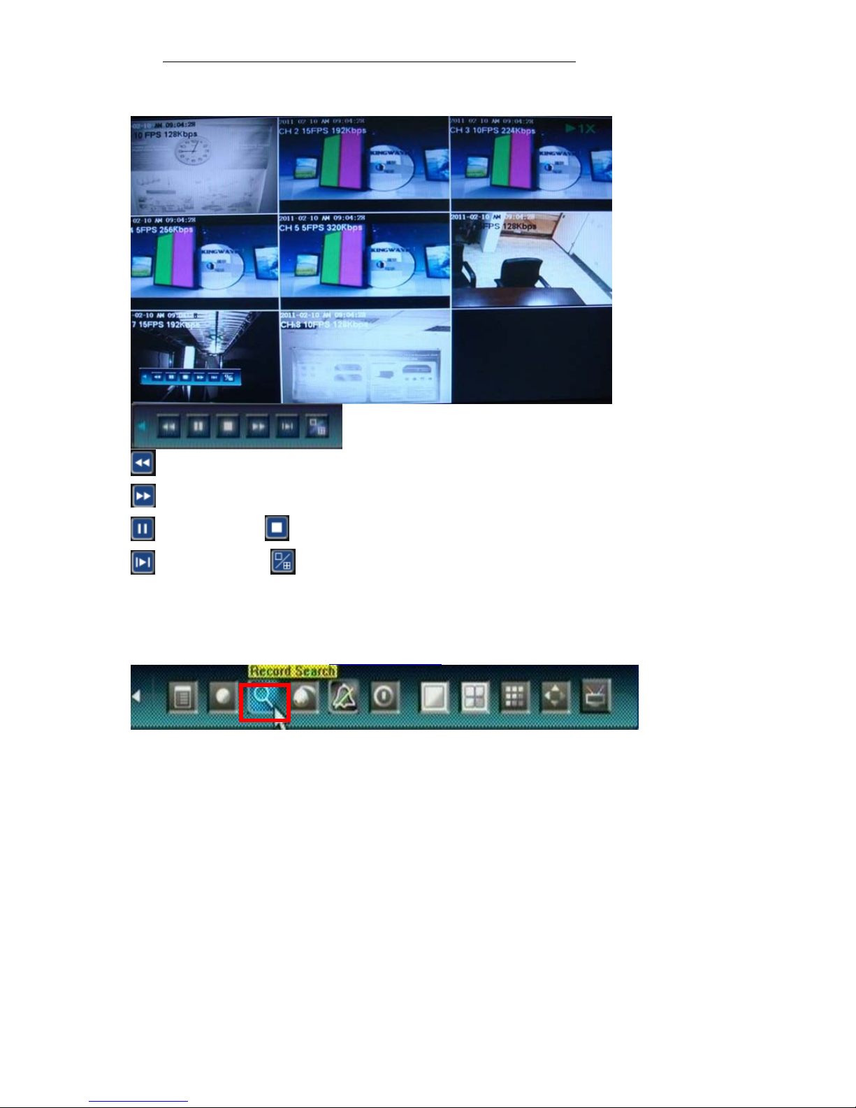
:Back backwards, the available speeds are 8X, 16X
:Fast forward, the available speeds are 2X, 4X, 8X, 16X, 1/8X, 1/4X and 1/2X.
:Pause :Stop playing.
:Go to next frame. :Click to switch from single camera to 4/9 camera.
4.6 Video Backup
Select <Tool Bar>→<Record Search> to search, backup and playback the specific record files you needs. Set the
start time and stop time as describe in 4.5 Video Playback
- 18 -
Page 20
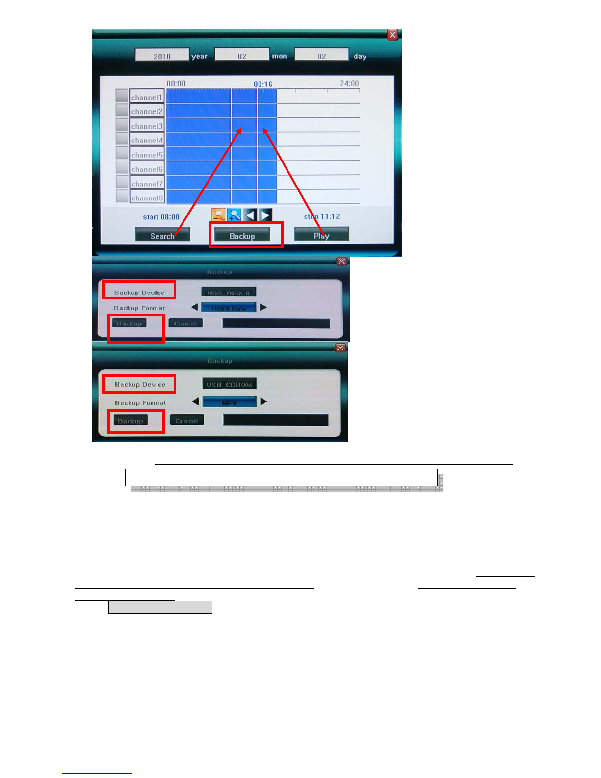
Click [Backup] to enter into the backup screen. System will detect all the backup devices available and
display them. Backup device can use USB flash drive, USB portable HDD and USB DVD Burner.
Please select the suitable device and record type according to requirement first, and click [Backup] to start save
audio/video. If there is no backup device found, a prompt tip will appear to remind users of connecting USB
device well.
The types of record video back up include H.264 Raw, MPEG4 and AVI for USB Flash Drive and portable
HDD(need external power supply), and only MPEG4 can be backed up for USB DVD Burner; when backup
in MPEG4 types, the special video decoder components WMP_MediaFilter .rar will also be backed up
together automatically. After it is decompressed and installed, the stored MPEG4 video files can be playback
only by Windows Media Player.
4.7 Play Backup Video on PC
For MPEG4 video format playback, you must install decoder component for Windows Media Player.
User can find the compressed files “WMP_MediaFilter.rar” inside the backup devices. Uncompressed the
“WMP_MediaFilter.rar” and execute “InstallFilter.bat” to install the decoder component, you can
- 19 -
Page 21
playback MPEG4 file by Windows Media Player.
g
Seq
Please note you don’t have to install this component for playback every time, it is one time installation; or
you can use the “MP4Player
package(Appendix D
For H264 video format playback, you may go to www.videolan.org/vlc
player according to your operation system, but must rename the stored video file from *.264 to *.h264.
” to play back MPEG4 format, please refer to Utility inside the CD of this
).
to download vlc binaries
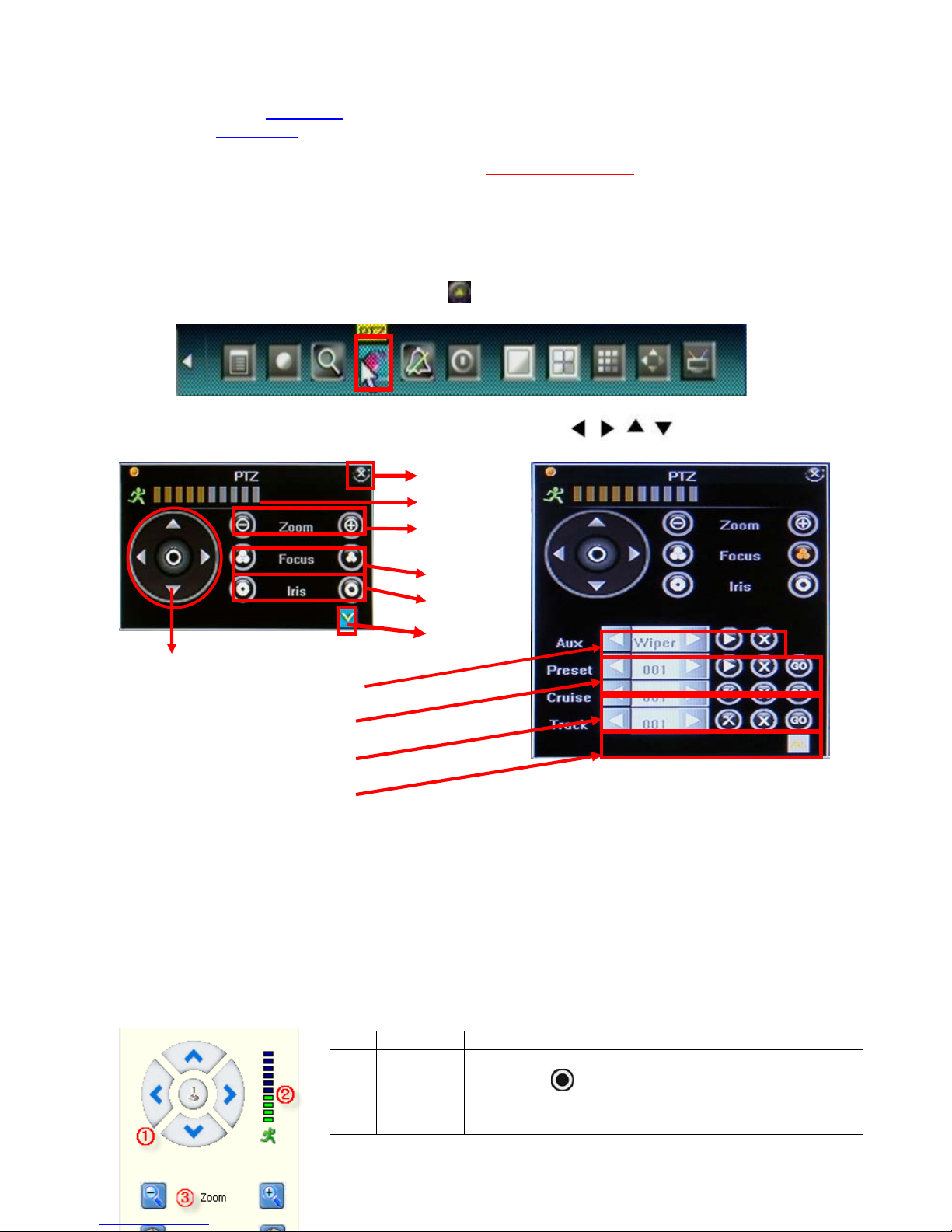
4.8 PTZ Control
Local Operate
Select single camera view and press <PTZ> button in front panel. Press direction key to move highlight
and press <Enter> to set the action. Press
functions descriptions
icon to open more menu, and please refer to next page for
Mouse operation is quite easy for PTZ control, just click and move, by remote control or keypad,
should press “Enter” key after any function keys such as
active.
1 Direction
○
6.Auxiliary
7.Preset
Internet explorer web browser Operate
⑧Cruise
uence
⑨Track
Close
2.Speed
3.Zoom
5.Focus
4.Iris
NO. Name Description
1
○
2
○
More menu
Click the arrow icons to control direction of PTZ. Click the
Direction
Speed Set the turning speed of PTZ camera.
center icon
refer to the PTZ manual for details of PTZ scannin
, , , pressed to make it
to call sequence or run scanning. Please
mode.
- 20 -
Page 22
3
j
4
5
Zoom
Iris
Focus
○
○
○
Click to zoom in/zoom out (it is disabled for cameras with
automatic focus).
Click to make the image brighter or darker (it is disabled
for cameras with automatic iris ad
ustment).
Click to focus-in and focus-out (it is disabled for cameras
with automatic focus).
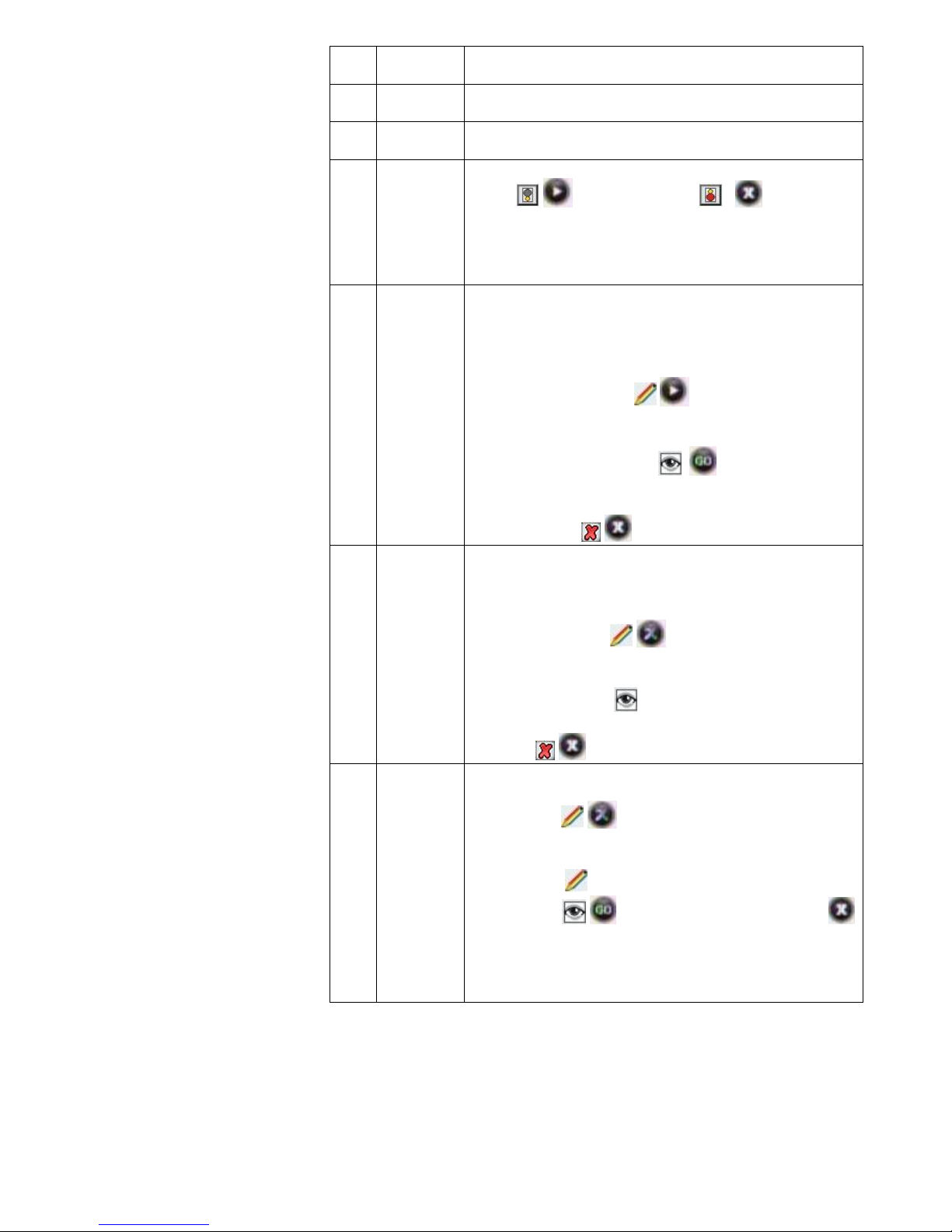
Open/close auxiliaries.
6
○
7
○
⑧
Auxiliary
Preset
Cruise
(Sequence)
Click
/ to open and click / to close, and
use arrow keys to choose. Different functions respond to
different protocols. The auxiliaries include light, rain
brash, and power etc. please refer to PTZ manual for
details.
Preset is to set camera position, focus, zooming, and iris
position, and then mark them in numbers for later calling.
1. Select the preset number you want to name as.
2. Position the camera as desired position including
direction, focus, iris and zoom value.
3. Click on the set button
/ .
call preset:
1. Select the preset number you want to call.
2. Click on the go-to button
./
Clear/reset preset:
Select the preset number you want to clear/reset. Click on
the clear button
/
Cruise is a running route of camera that passes through
multiple presets.
Set sequence:
1. Select preset number you want to call.
2. Click on set button
/ .
3. Repeat step 1 and 2 to add the other presets till
finishing.
⑨
Track
4. Click on run button
.
Clear sequence:
Click on
/ button to clear sequence.
Track is a continuous running route of camera.
Set track:
1. Click on
/ to start setting.
2. Move camera as the track and start/stop time you want
it to run.
3. Click on “
/”OK” to finish setting.
4. Click on / to run track and click again or
to stop running.
NOTE: Whether Track is supported or not is depending on
the type of PTZ.
- 21 -
Page 23
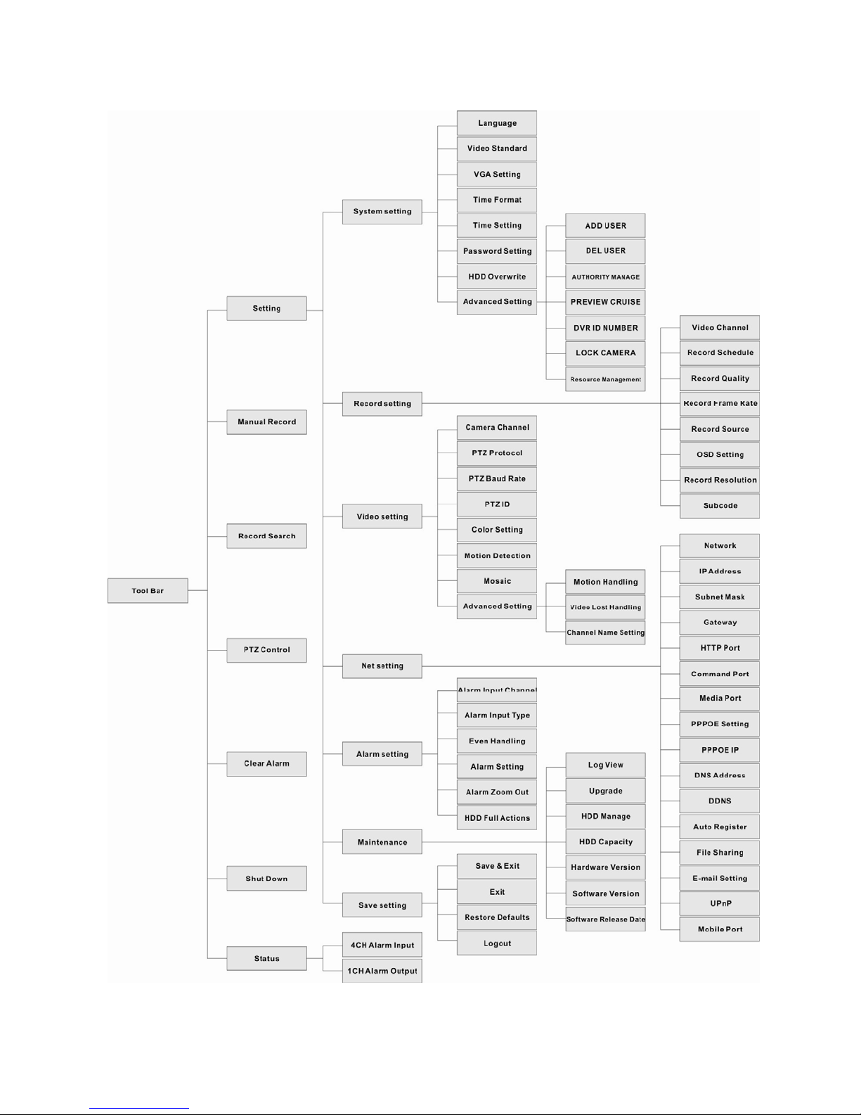
5. DVR Setting
5.1 Menu Tree & Operate
- 22 -
Page 24
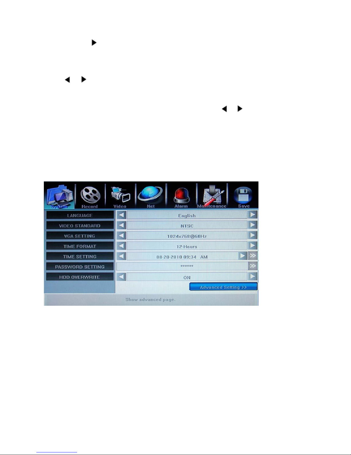
General Operations
Press 【MENU】 button to enter into system setting screen.
Press 【●】 button to start/stop recording manually.
Press 【
Press【PTZ】 button to enter into PTZ control screen.
Menu Selection
The highlight menu is the current active one. User can move highlight icon to the menu needed using
】,【 】 button, and press 【Enter】 button to confirm selection, or press 【ESC】to return to upper
menu.
Menu Operation
Use 【▲】, 【▼】to move highlight for configure items. Press 【
Use mouse to input via on-screen keyboard or input value from remote controller.
Press【>>】open sub menu, and 【ESC】return upper menu.
Save/Exit
User can click × button on the right upper corner, or single right click mouse, or press 【ESC】 button to
enter into the Save & Exit screen. You can select exit directly or exit after being saved.
】 button to play record file.
5.2 System Setting
】,【 】button to change parameter.
5.2.1 Language
Change DVR menu text and OSD language depend upon your requirement.
**Take effect immediately **
5.2.2 Video Standard
Change DVR and camera video system, NTSC or PAL system.
**Take effect after being saved. **
5.2.3 VGA Setting
Switch different VGA output resolution, there are 800x600@60Hz, 1024x768@60Hz
1280x1024@60Hz, 1440x900@60Hz
if wrong VGA resolution to make the LCD display distorted, please press “ESC” -> “2” -> “ESC”
continuously(not over 3 second) of front panel/remote cont rol to res tore th e disp lay resolution to be
800x 600
5.2.4 Time Fomat
Switch time format between 12-Hours or 24-Hours.
- 23 -
Page 25
**Take effect immediately **
5.2.5 Time Setting
Select time display way and adjust date/time of DVR, you can choose “AM”/”PM” display if Time Format
is “12-Hours”, which will change the Chapter 5.7.1 Log View
**Take effect immediately **
In order to avoid record files’ time confusion, you’d better
time display format
stop recording before modifying system time
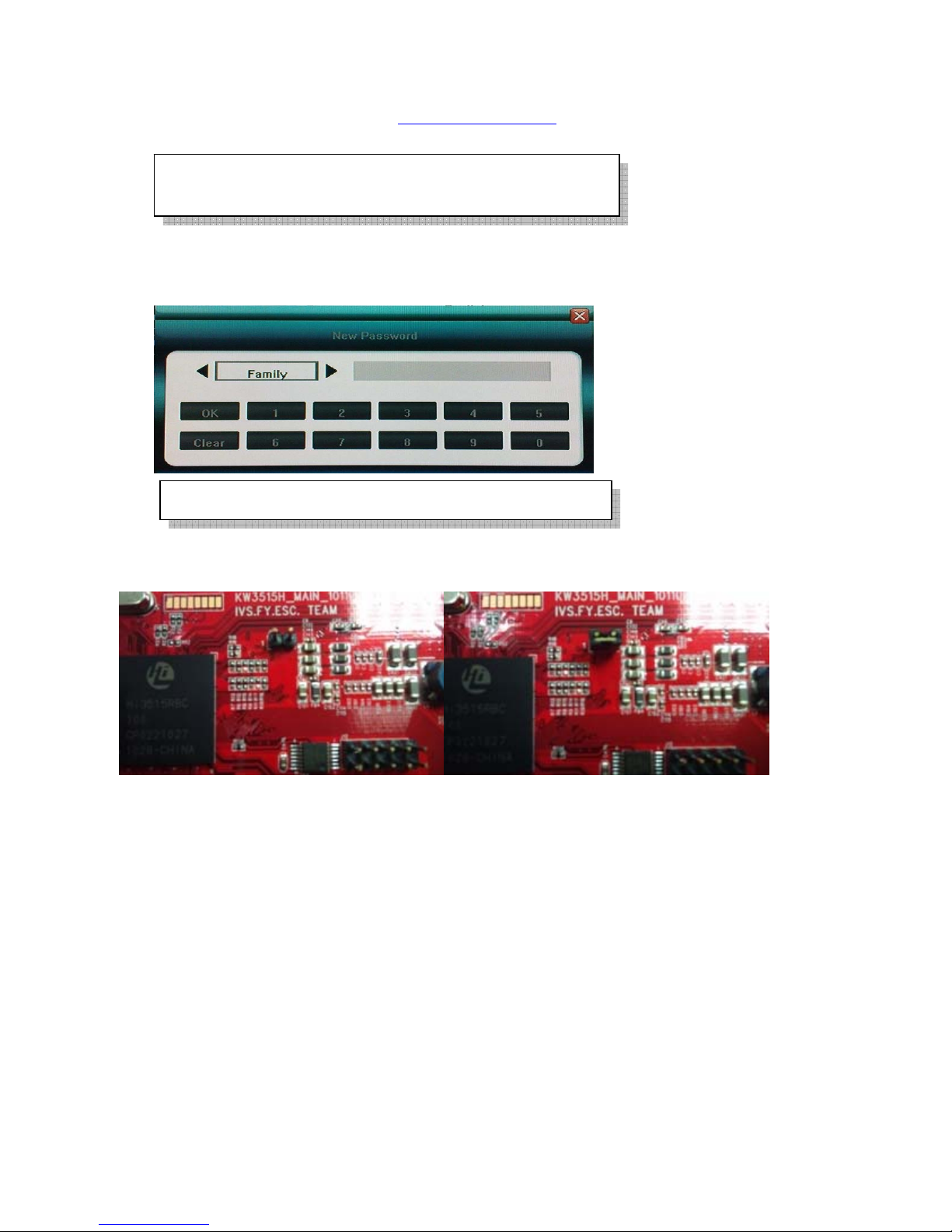
5.2.6 Password Setting and what if forgotten
Choose any account to change its password (password is only digital)
connector location, and find some jumper cap to make it closed(short) and hold it until “beep” sound heard, it
will return back to default password of “Admin” and “User” account.
Default password of Admin is [888888] User is [666666]
If password forgotten, turn off the machine, open this DVR case, find the JP17 jumper, it is near the SATA
5.2.7 Hard Disk Overwrite
Set up hard disk full action – over write(ON) or stop recording(OFF)
5.2.8 Create/Delete User Account, assign authorities, setup SEQ Display(Preview
Cruise) and Lock Cameras:
Click “Advanced Setting” of “System”, enter the following setup:
- 24 -
Page 26
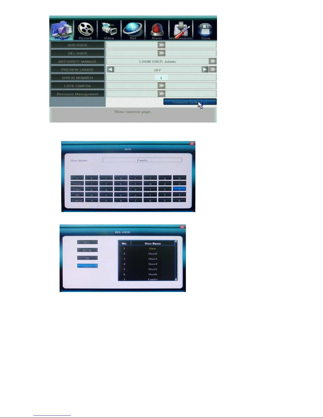
Add User Account
Enter “ADD USER” to add user account, most 7 users accounts can be produced, and there will be
warning message if exceed.
Delete User account
Enter “DEL USER” to delete user account
Authority Manage
Operation authority of DVR for “User” account can be defined by system. There are two conditions to
apply restriction, Local operati on and Remote access. The user accounts are not allowed to operate
DVR setting. Enter “Authority Manage”, choose User account, and assign its authorities.
- 25 -
Page 27
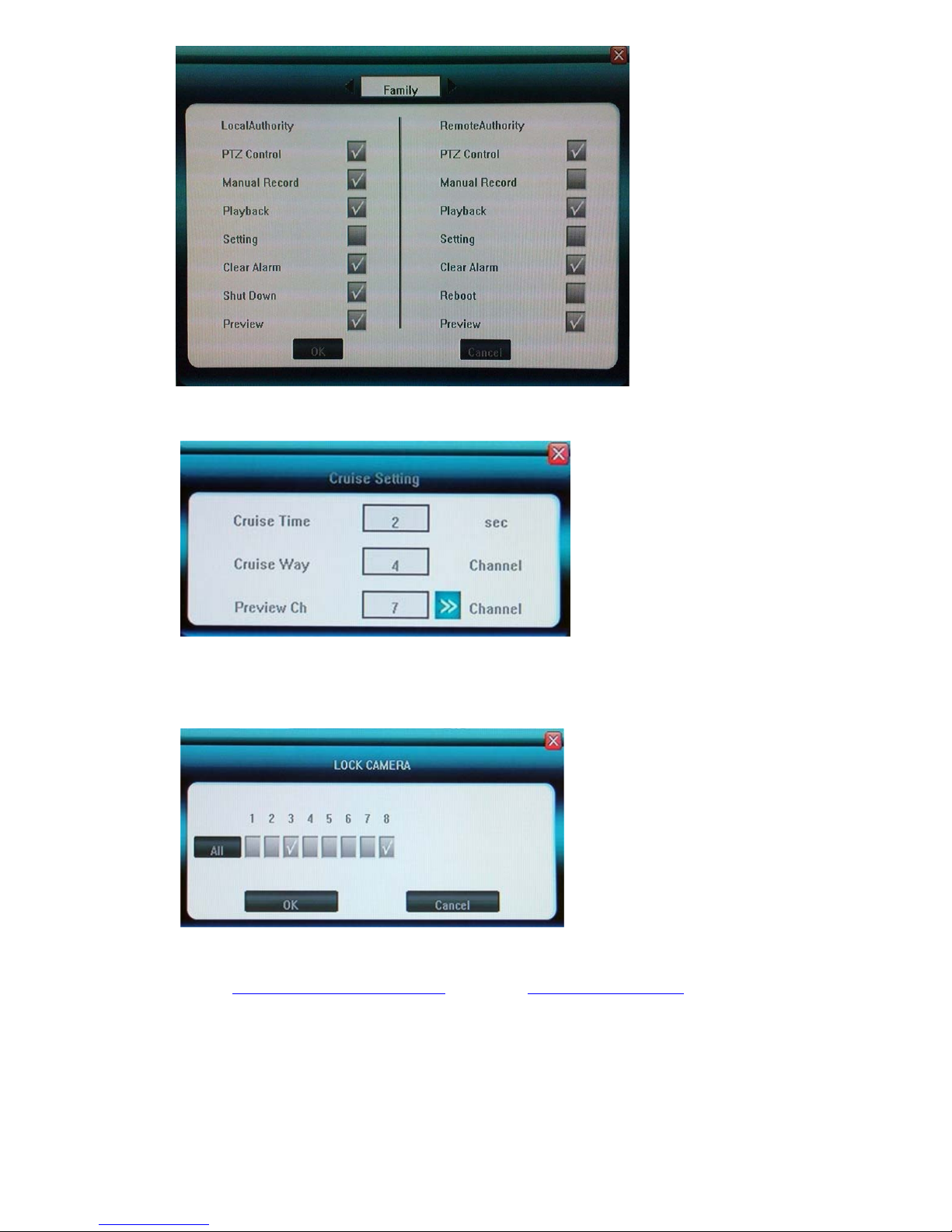
SEQ Display(Preview Cruise)
Set up the SEQ display (Cruise Way) for 4CH(1/4CH) and 8CH(1/4/9CH), and the time interval(Cruise
Way) in seconds between them, also choose the channels for Preview Cruise
DVR ID NUMBER
It is future growth, to set up the same ID number with RS422 Keyboard if you want to control DVR
from keyboard.
Lock Cameras(Cover Cameras)
Administrator [Admin] can cover cameras that user accounts cannot see locally and remotely.
5.2.9 Resource Management
Before set up the Chapter 5.3.4 Record Frame Rat and Chapter 5.3.7 Record Resolution for this DVR, you have
to assign the resource managements first as below : System -> Advanced Setting -> Resource Management
- 26 -
Page 28
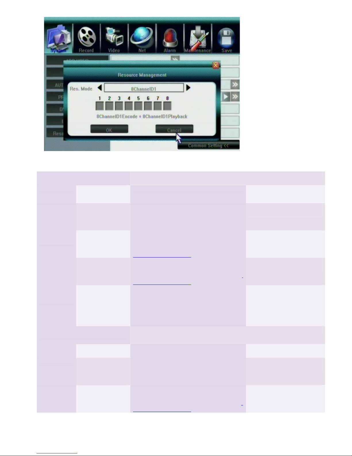
Please refer to following Resource Management table for 4CH and 8CH, these DVR have different Record and
Playback mode as below:
4CH Resource Management and
Recording/Playback mode
Set up Mode Record and
Playback mode
Maximum Record/Playback resolution and frame rate for each channel)
Function Note
4 Channel D1 4 Channel D1
Encode + 4
Channel D1
Playback
4 Channel
CIF
4 Channel CIF
Encode + 4
Channel CIF
Playback
4 Channel
HD1
4 Channel HD1
Encode + 4
Channel HD1
Playback
1 Channel D1
+ 3 Channel
CIF
1 Channel D1
Encode + 3
Channel CIF
Encode + 2
Channel D1
Playback
8CH Resource Management and
Recording/Playback mode
Mode Record and
Playback mode
8 Channel D1 8 Channel D1
Encode + 8
Channel D1
Playback
8 Channel
CIF
8 Channel CIF
Encode + 8
Channel CIF
Playback
Any channel can Record/Playback maximum:
NTSC: 15Fps D1, 30FPS(HD1, CIF)
Just press “OK” to finish set
up, no need click channel no.
PAL: 12Fps D1, 25FPS(HD1, CIF)
Any channel can Record/Playback maximum
NTSC: 30FPS CIF
Just press “OK” to finish set
up, no need click channel no.
PAL: 25FPS CIF, can not set up D1/HD1 in
5.3.7 Record Resolution
Any channel can Record/Playback maximum
NTSC: 30FPS(HD1, CIF)
Just press “OK” to finish set
up, no need click channel no.
PAL: 25FPS(HD1, CIF), can not set up D1 in
5.3.7 Record Resolution
NTSC: Record/Playback 30FPS(D1, HD1,
CIF)
PAL: Record/Playback 25FPS(D1, HD1,
CIF)
Click only one channel to
have maximum 30FPS or
25FPS D1/HD1, others are
CIF
Playback only two channels mixed
Maximum Record/Playback resolution and frame rate for each channel
Function(Can playback 8 Channels) Note
Any channel can Record/Playback maximum:
NTSC: 7FPS(D1), 15FPS(HD1), 30FPS(CIF)
Just press “OK” to finish set
up, no need click channel no.
PAL: 4FPS(D1), 12FPS(HD1), 25FPS(CIF)
Any channel can Record/Playback maximum
NTSC: 30FPS CIF
Just press “OK” to finish set
up, no need click channel no.
PAL: 25FPS CIF, can not set up D1/HD1 in
5.3.7 Record Resolution
- 27 -
Page 29
8 Channel
HD1
1 Channel D1
+ 7 Channel
CIF
2 Channel
HD1 + 6
Channel CIF
8 Channel HD1
Encode + 8
Channel HD1
Playback
1 Channel D1
Encode + 7
Channel CIF
Encode + 1
Channel D1
Playback
2 Channel HD1
Encode + 6
Channel CIF
Encode + 2
Channel HD1
Playback
5.3 Record Setting
Any channel can Record/Playback maximum
NTSC: 15FPS(HD1), 30FPS(CIF); PAL:
12.5FPS(HD1), 25FPS(CIF), can not set up
D1 in 5.3.7 Record Resolution
NTSC: Record/Playback 30FPS(D1, HD1,
CIF)
PAL: Record/Playback 25FPS(D1, HD1,
CIF)
Playback only one channel
NTSC: Record/Playback 30FPS(HD1, CIF)
PAL: Record/Playback 25FPS(HD1, CIF)
Playback only 2 channels mixed
can not set up D1 in 5.3.7 Record
Resolution
Just press “OK” to finish set
up, no need click channel no.
Click only one channel to
have maximum 30FPS or
25FPS D1/HD1, others are
CIF
Click only two channels to
have maximum 30FPS or
25FPS HD1, others are CIF
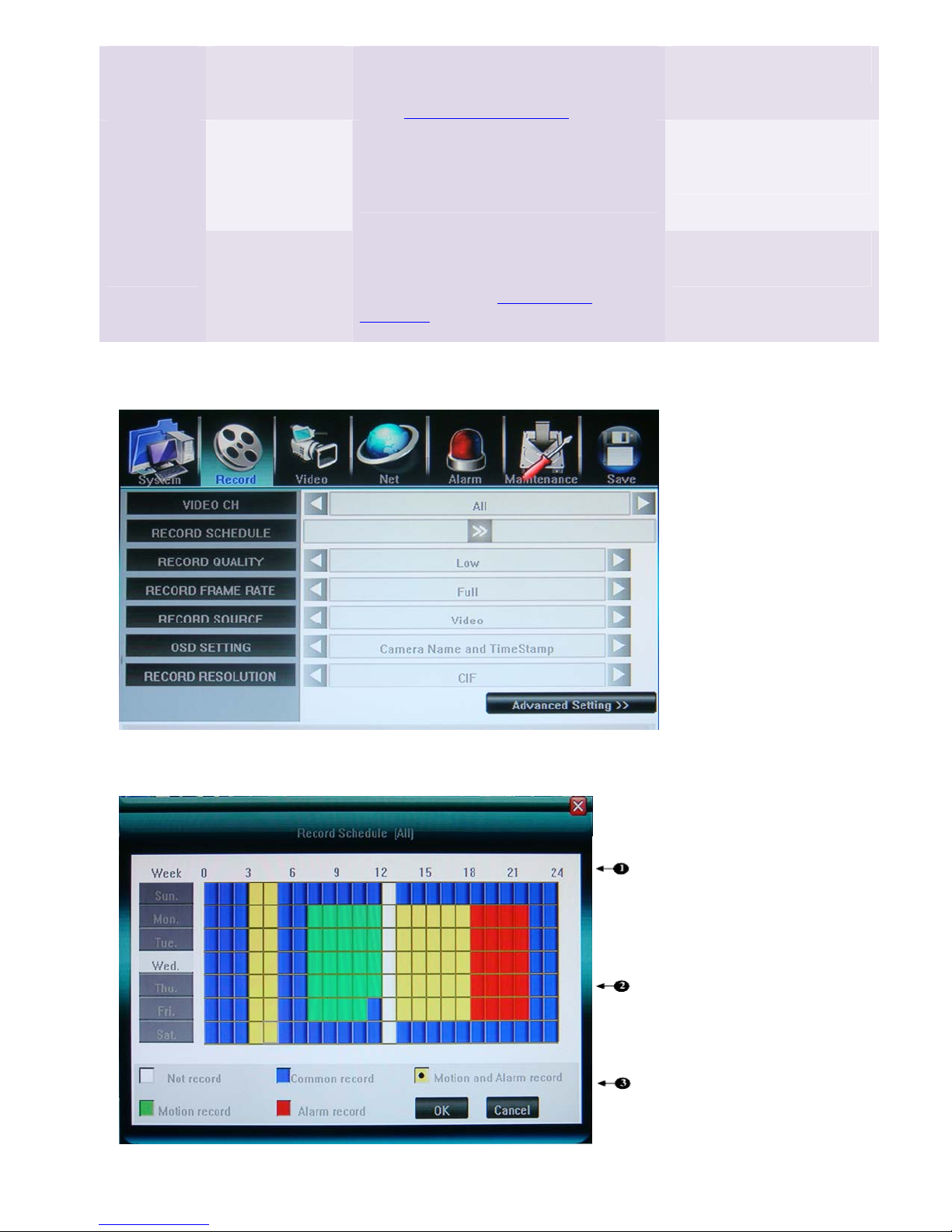
5.3.1 Video Channel
Select channel number for apply record setting. Select [ALL] for apply to all channels.
5.3.2 Record Schedule
- 28 -
Page 30

①. The current recording channel number
②. The record schedule
③. Description of record type
z no record (white ): No recording during this time
z common reco rd (blue
z move record (green
z alarm record (red
z move and alarm record (yellow ): Recording triggered by either alarm or motion
detection.
System provides a recording option for 24 hours every day and Sunday through Saturday every week. Unit
is hour. One grid indicates one hour.
Mouse set up
region; color of the grid will change relevantly; left click the week day if you want that day with all the same
record type.
Faceplate or Remote control buttons
Using【Direction】buttons to a time grid, select the record type by repeat pressing【Enter】button until done;
or press the
region, and press again to finish; color of the grid will change relevantly; Move to the week day, and repeat
pressing【Enter】button until done if you want that day with all the same record type.
Select OK to confirm settings. The settings will take effect after being saved.
- select a record type, move to a time grid, left click it or hold it, and dragging to the desired
–
or (faceplate button), or [FN] (remote control), and dragging to the desired
): Recording always
): Motion-detection triggered recording
): Alarm-triggered recording
When motion detection & alarm recording is selected, the motion
detection sensitivity and area should be set ahead. Please refer to
5.4.6 Motion Detection Settings
for details. When alarm recording
is selected, the alarm triggering settings should be set ahead.
Please refer t o 5.6.3 Event Handling
for details; the recording time
would be 30 sec. when motion detect or alarm happened except
continuous happened, which will be accumulated to the last one.
5.3.3 Video Quality
Select quality level for record audio/video. The pre-define selection from Best 768kbps ÆHigh 640kbps
ÆMid 512kbps ÆLow 384kbps or user define. User can manually input bit rate for recording. (Kbit/s). The
higher video bit rate would impact network remote viewing if you don’t open the sub code(sub streaming) for
dual streaming, please refer to 5.3.8 Dual Streaming
5.3.4 Record Frame Rate
Select recording frame rate per second. The pre-define selection from Full (30/25fps) Æ 15 fps Æ 7fps Æ 3fps
Æ 1 fps or user define; please refer to Chapter 5.2.9 Resource Management for details
5.3.5 Record Source
Two type selection of recording, Video with audio or Video only.
Only select “Video with audio”, can hear the sound via internet or playback
5.3.6 OSD Setting
Define OSD (On Screen Display) string. The options have as following
1) Camera’s Name and Time Stamp
2) Camera Name
3) Time Stamp
4) None
Only select “Time Stamp”, can see time display when playback
.
- 29 -
Page 31
5.3.7 Record Resolution
Choose record resolution of the channel selected, and must choose the same resolution for all channels,
please refer to Chapter 5.2.9 Resource Management for details
1) CIF(352 x 240, or 352 x 288)
2) Half D1(704 x 240, or 704 x 288)
3) D1(704 x 480, or 704 x 576)
Please note 4CIF=2 Half D1=D1, so that “Record Frame Rate” would be reduced automatically
even you set up as “Full” for D1 and Half D1.
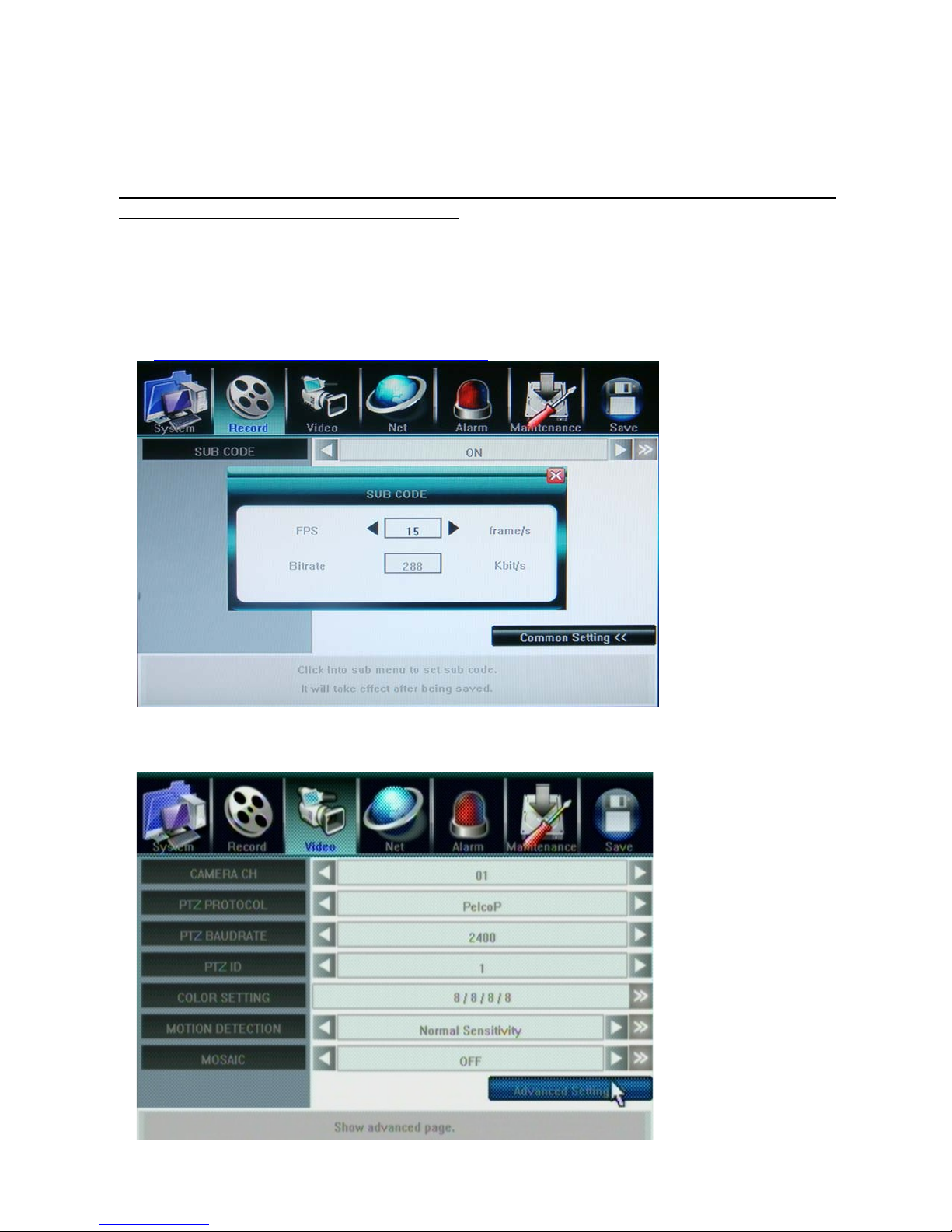
5.3.8 Dual Streaming for Network(Record-Advanced Setting)
SUB CODE
By default, DVR use recording streaming for IE Browser viewer and mobile streaming. Enable sub code
can customize the frame rate and bitrate for IE client viewer and mobile streaming in case of limited
upload bandwidth, and they can be setup independently for every channel. For IE set up, please refer to
ChannelÆ Camera setting, Sub Bitstream, Subcode
5.4 Video Setting
- 30 -
Page 32
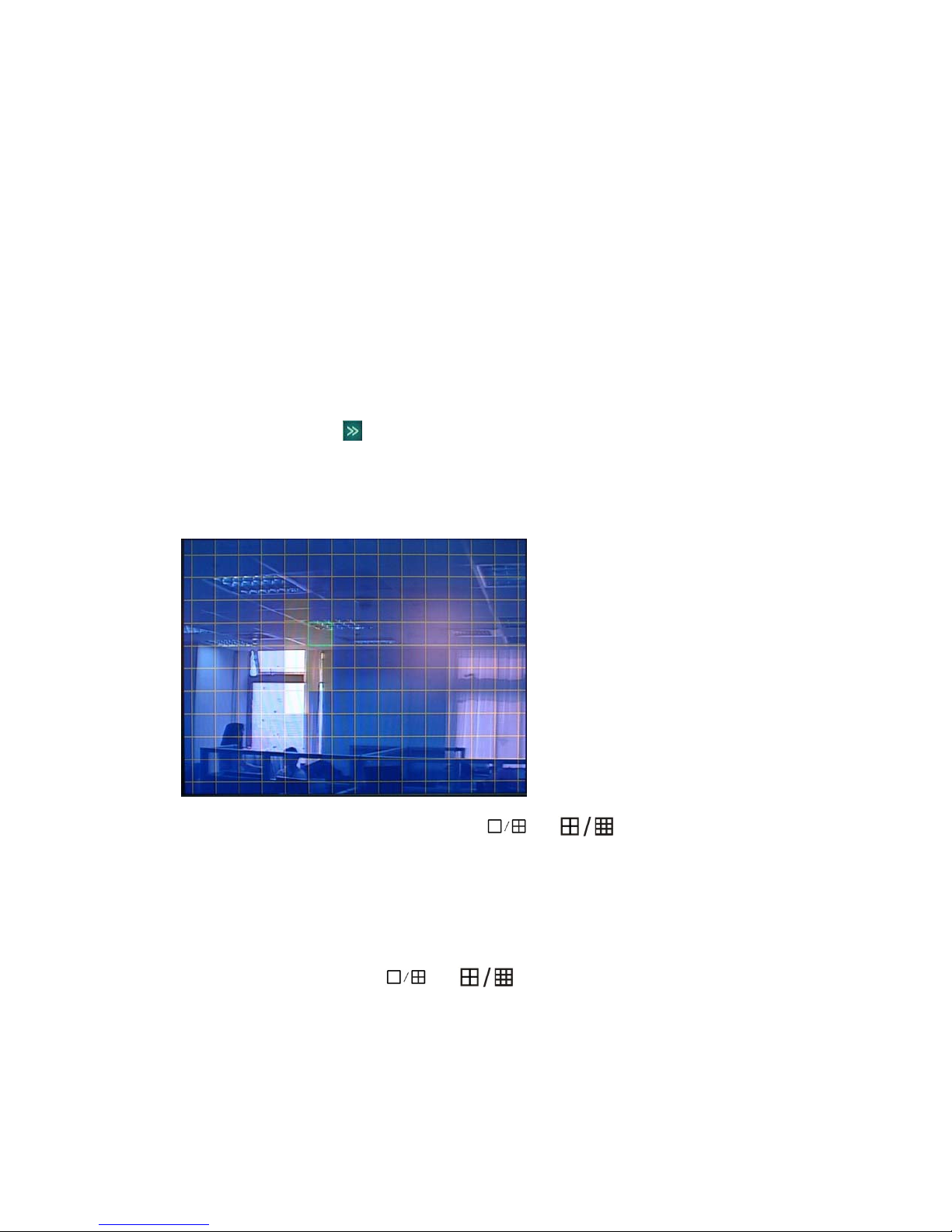
5.4.1 Camera Channel
Select camera channel for apply camera setting. Select [ALL] for apply to all channels.
5.4.2 PTZ Protocol
Select PTZ device protocol. Support CLT-618, JY2000, Philip, Pelco-D, Pelco-P, Panasonic, Samsung, SYYT,
TD500, Tiandy, VIDO, VTS, YAAN, Yiboer and etc.
5.4.3 PTZ Baud Rate
Select PTZ device baud rate. Support 1200, 2400, 4800, 9600.
5.4.4 PTZ ID
Select PTZ device ID. From 0~255
5.4.5 Color Setting
Adjust camera color attribute, by default the value is 8.
z Brightness: 1 ~ 16
z Contrast: 1 ~ 16
z Hue: 1 ~ 16
z Saturation: 1 ~ 16
5.4.6 Motion Detection Setting
Enable this function and click the of the Motion Detection”, you can find the following setup
Sensitivity of motion detection
There are three level sensitivity of motion detection.
Highest ÆNormal Æ Low or Disable
Configure motion detection by region.
Press 【>>】on screen to pop up sub windows for region setting.
There are totally 16 x 12 individual blocks for a camera view. Each cell can be turn on(Blue) or
off(Clear) by single mouse left-click, or press
(remote control); you may define multiple-cell areas by clicking mouse or pressing button on one cell
and dragging the selection in the desired direction, press or click again to confirm; by mouse
right-click or press [ESC] to finish the setting.
5.4.7 Privacy Mask(Mosaic)
Each camera can define multiple regions for privacy protection. Click 〖>>〗open sub windows By
single mouse left-click; or press
control), and define the single cell by [Enter] (faceplate or remote control button); or you may define
multiple-cell areas by clicking mouse or pressing button on one cell and dragging the selection in the
desired direction, press [Enter] (faceplate or remote control button) to define the region; by mouse
right-click or press [ESC] to finish the setting.
or (faceplate button), or press [FN]
or (faceplate button), or press [FN] (remote
- 31 -
Page 33
To cancel the privacy region, by use mouse/ left-click, or press
or (faceplate button),
or press [FN] (remote control) to move to the privacy region, and press [ECS] or mouse/right-click to
confirm; by mouse right-click or press [ESC] again to finish the setting and return back to manual.
Each privacy region will show only gray color in live view windows and being recorded. Support
Maximum 4 regions.
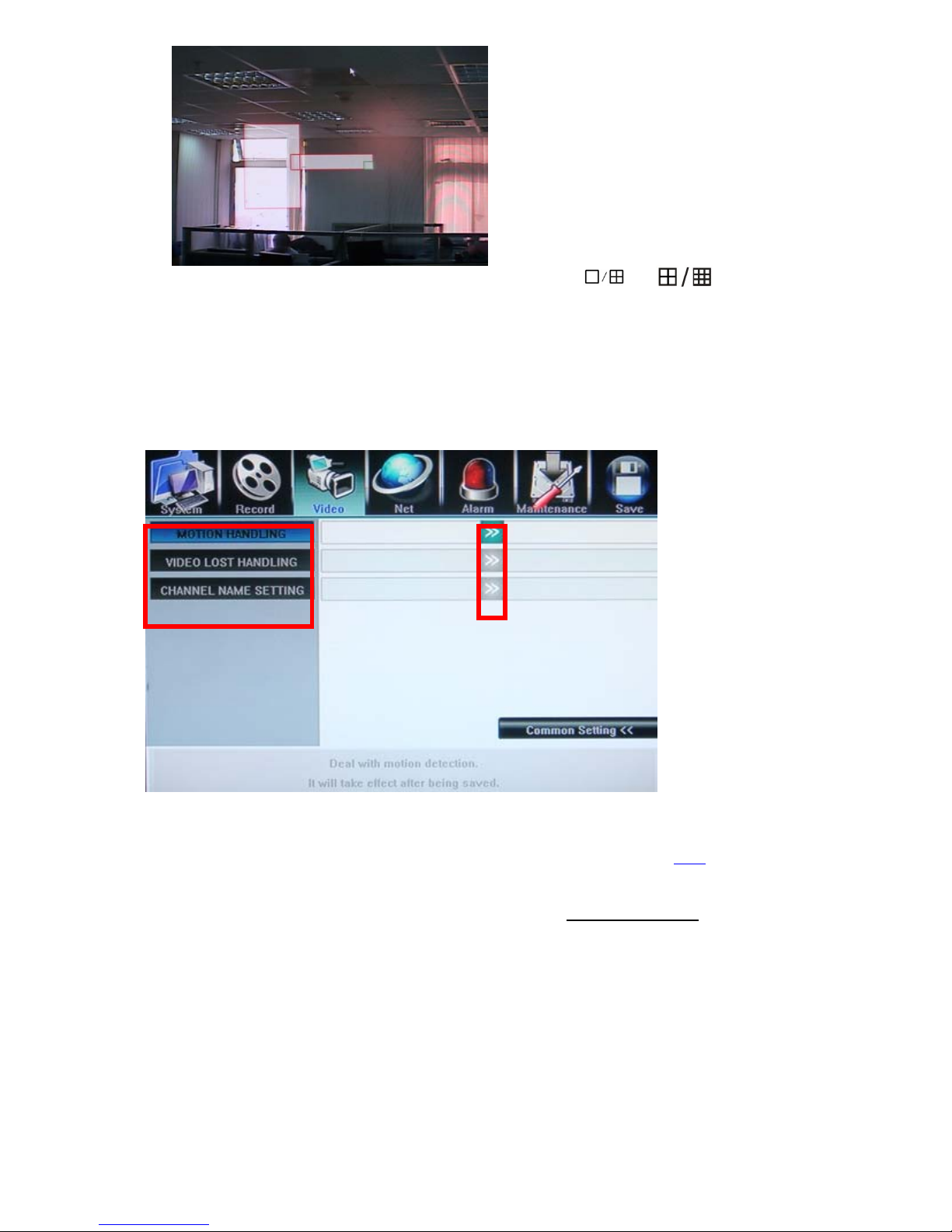
5.4.8 Motion, Video Lost and Channel Name(Video- Advanced Setting)
Motion Handling & Video Lost handling
User can pre-define correspond actions while DVR handling the event such as motion detection, video
lost, following is the action list,
z Record: Start record immediately for selected channels
z Alarm Zoom Out: display channels when motion happened, please refer to 5.6.4
z Alarm Out: Set the Alarm output enable
z Buzzer: Set the internal Buzzer enable
z E-mail: Send E-mail with Snapshot picture(please refer to 5.5.6 E-mail Server
the E-mail address list)
z UPLOAD: upload these events message to IE or CMS server, to be displayed at the top right corner
- 32 -
about how to set up
Page 34
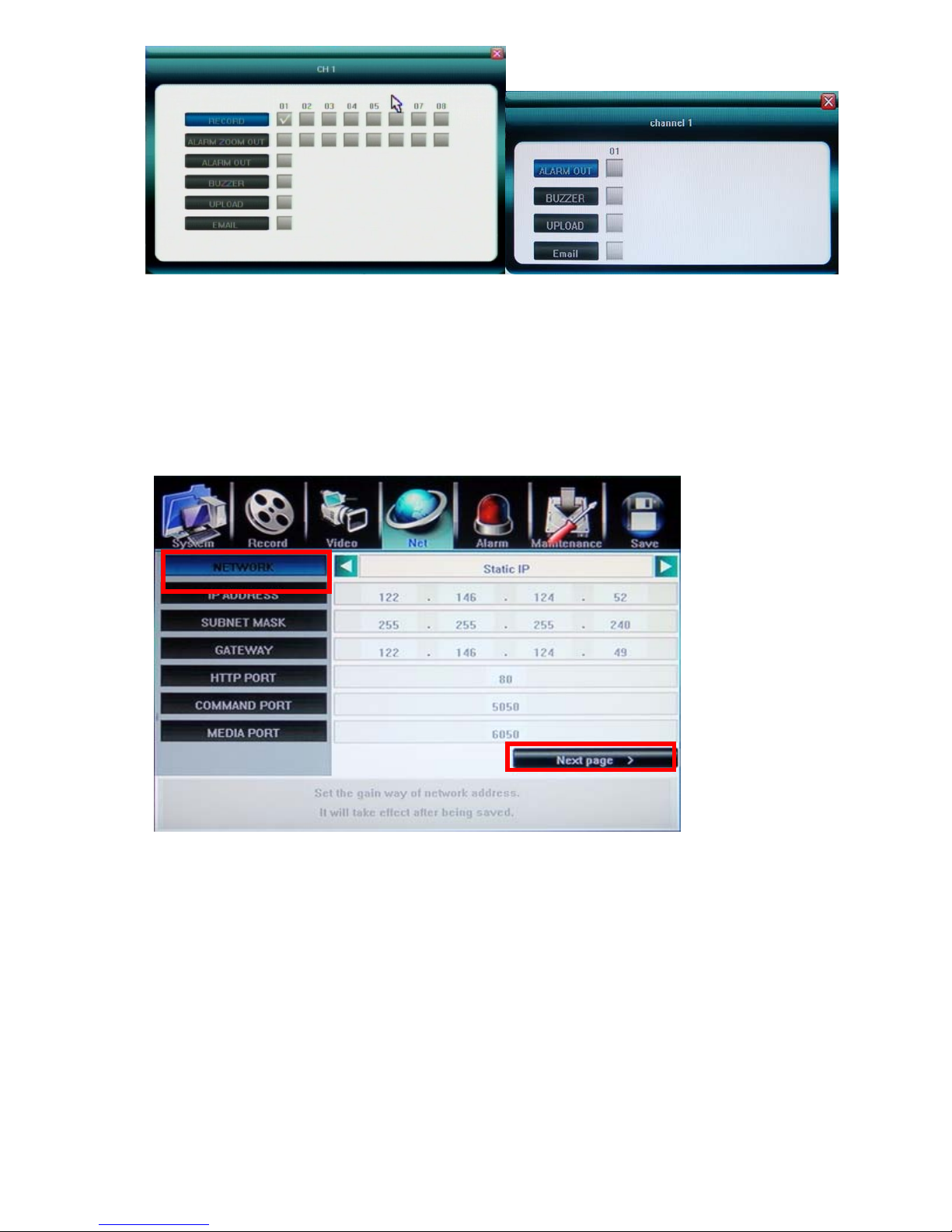
Motion Detect Video Loss
Channel Name Setting – at most 16 characters, but only can display 11 characters
5.5 Net Setting
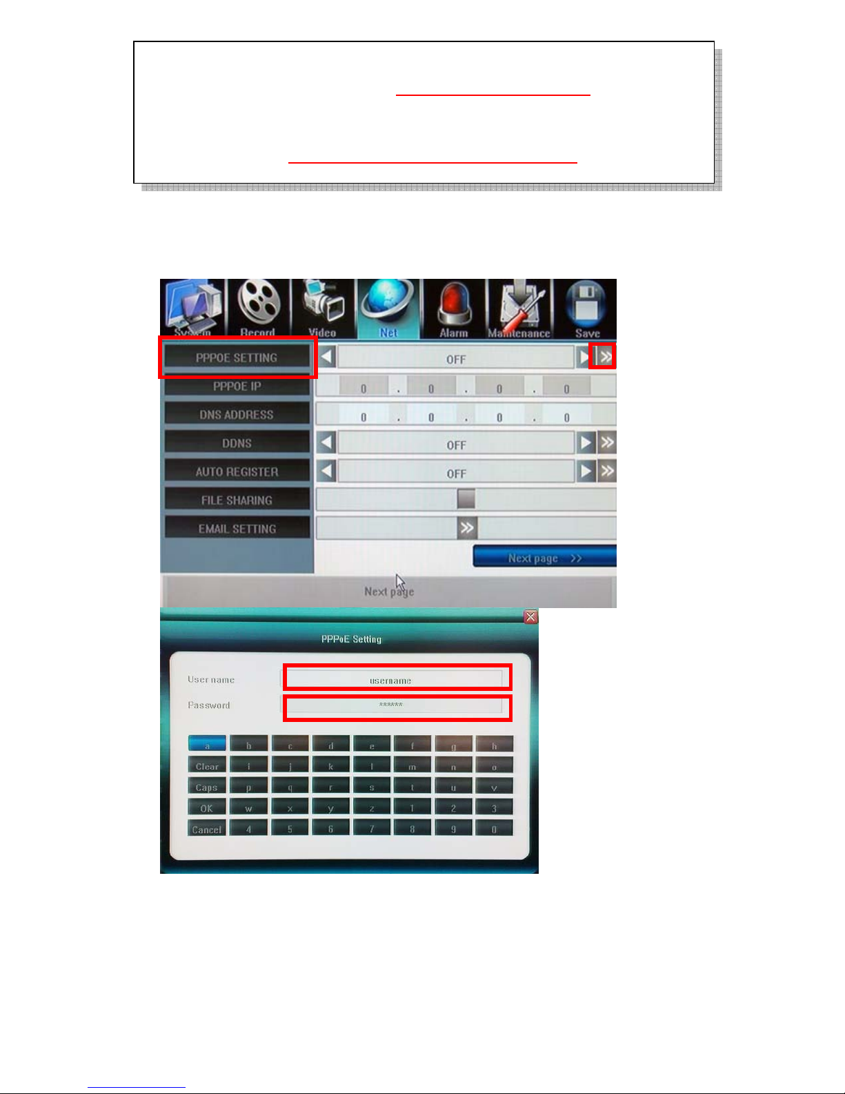
5.5.1 Network (Static IP/DHCP)
DVR support two methods to acquire IP address,
Automatic acquire IP address by DHCP client model.
Manual assign IP address by Static IP model.
PPPoE for ADSL dial-up network are supported, please click Next Page.
5.5.2 Http Port
By default is port:80, user can specify different port number.
5.5.3 Command Port
By default is port:5050, user can specify different port number.
5.5.4 Media Port
By default is port:6050, user can specify different port number.
- 33 -
Page 35
If DVR installed behind a Router to share a single public IP address. Be sure to configure
the “Port Forwarding” or “Virtual Server” for those three network port and Mobile
surveillance Port:7050; you may surf http://portforward.com
information.
Http port:80, Command port:5050, Media port:6050 and mobile surveillance port:7050
must open/allow to upload to WAN interface if DVR installed behind a Firewall server; for
port no., please refer to http://www.iana.org/assignments/port-numbers
information
for more
for more
5.5.5 PPPoE/DDNS(Net- Second Page]
PPPoE Setting
Click 〖>>〗to open sub window and input ADSL account and password from Internet
Service Provider.
DDNS
Click 〖>>〗to open sub window and input DDNS account and password from DDNS Service
Provider. User must apply DDNS service account at first.
- 34 -
Page 36
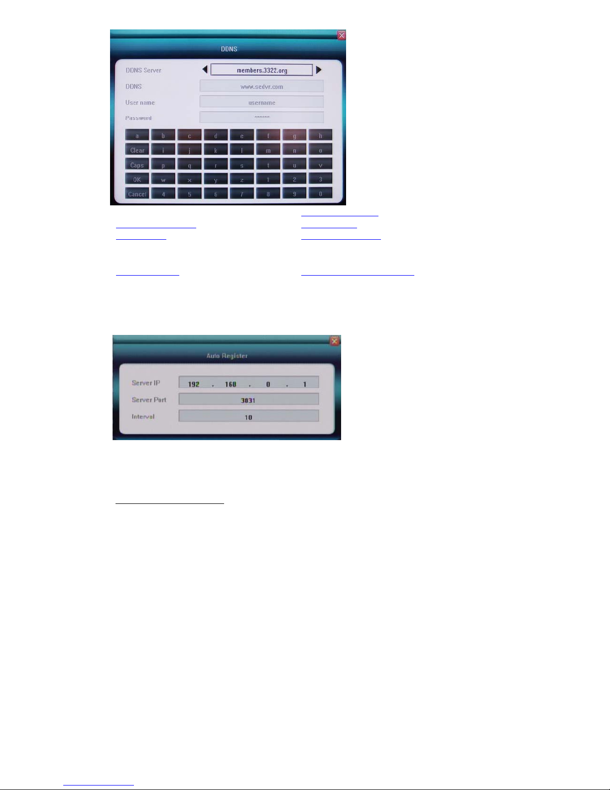
update.ods.org www.easydns.com
www.justlinux.com
www.hn.org
www.dyns.cx
www.zoneedit.com
members.3322.org members.3322.org(static)
members.dyndns.org members.dyndns.org(static)
www.EZ-IP.net
www.penguinpowered.com
members.dhs.org cgi.tzo.com
Auto Register
DVR can configure to automatically register to CMS, input CMS Server IP address, Server Port:
8003(default) and register time interval in seconds(register to CMS server if failed); it is not
necessary setup because you can add this DVR in CMS server manually.
File Sharing
Check to activate files sharing function, then able to visit video files in DVR HDD via network
neighborhood.
How to visit shared files:
Double click network neighborhood, input ftp://IP address, such as ftp://192.168.10.220 , to enter the
login page, type in the super authority “Admin” and password, the shared files can be accessible now,
click into folder of “videoout” to check video files
.
5.5.6 Email Server set up for Email notify
User can add multiple e-mail address of recipients for alarm, motion and video loss notification. Input
standard SMTP mail server IP address. Please make sure you have user account and password in
advance.
- 35 -
Page 37
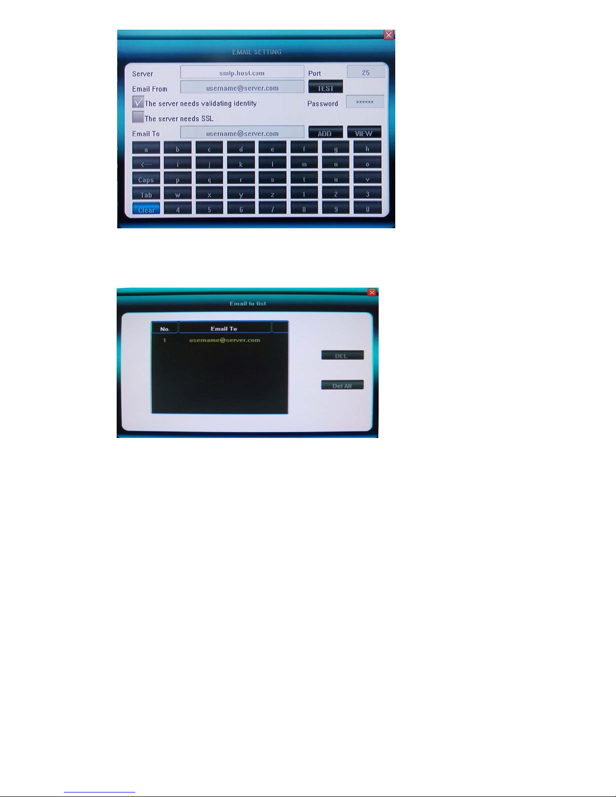
The Email To field indicates the recipients of alarm emails, and the Email From field indicates the
email account from which the message will be sent. You can input the Email To field and [ADD] it
into the list of recipients. You can [VIEW] the list of recipients in the Email to list, where you can
delete if no need any more. [SSL] option is necessary if you use Gmail.
You m ay us e [TEST] to test the Email to list while input, to make sure that they are communicated,
please remember the server information and Email From information must be corrected, and DVR
must be internet connected before [TEST]
5.5.7 UPnP and Mobile port(3 rd page in Net Setting)
Go to Net -> Next page -> Next page, you can see following
UPnP
Enable UPnP function if it connected UPnP router, no need to open the ports(port forwarding, port mapping)
inside the router, please note:
The UPnP function of the router connected must be enabled
The router must connect internet, not intranet
If still can not pass through the router, you may change the port no.(80, 6001, 6002, 6003)
and try again .
- 36 -
Page 38
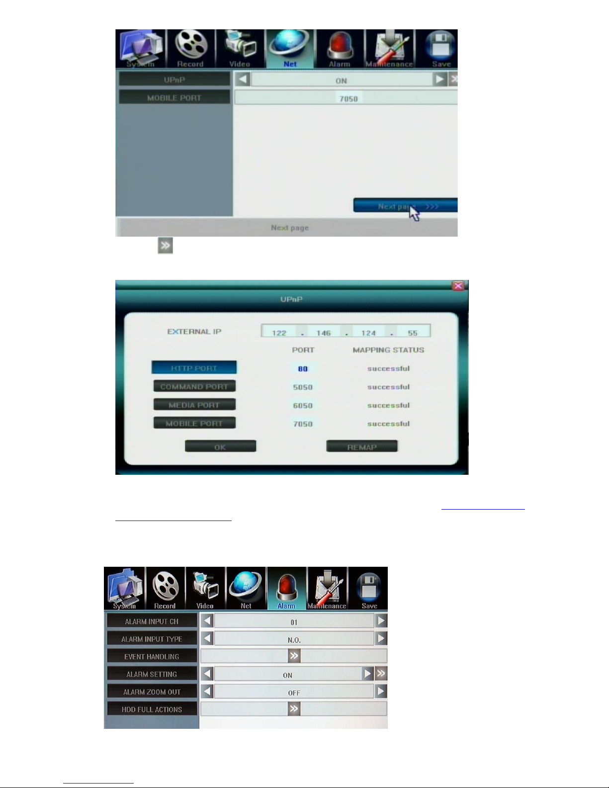
Click the
screen shot if successful in UPnP mapping
Mobile PORT
By default is port: 7050, user can specify different port number, please refer to Chapter 7. 3G/3.5G
Mobile Phone/PDA Support for details.
, it will appear “Query port mapping status” message, and you will find the following
5.6 Alarm Input/output Setting
5.6.1 Alarm Input Channel
- 37 -
Page 39
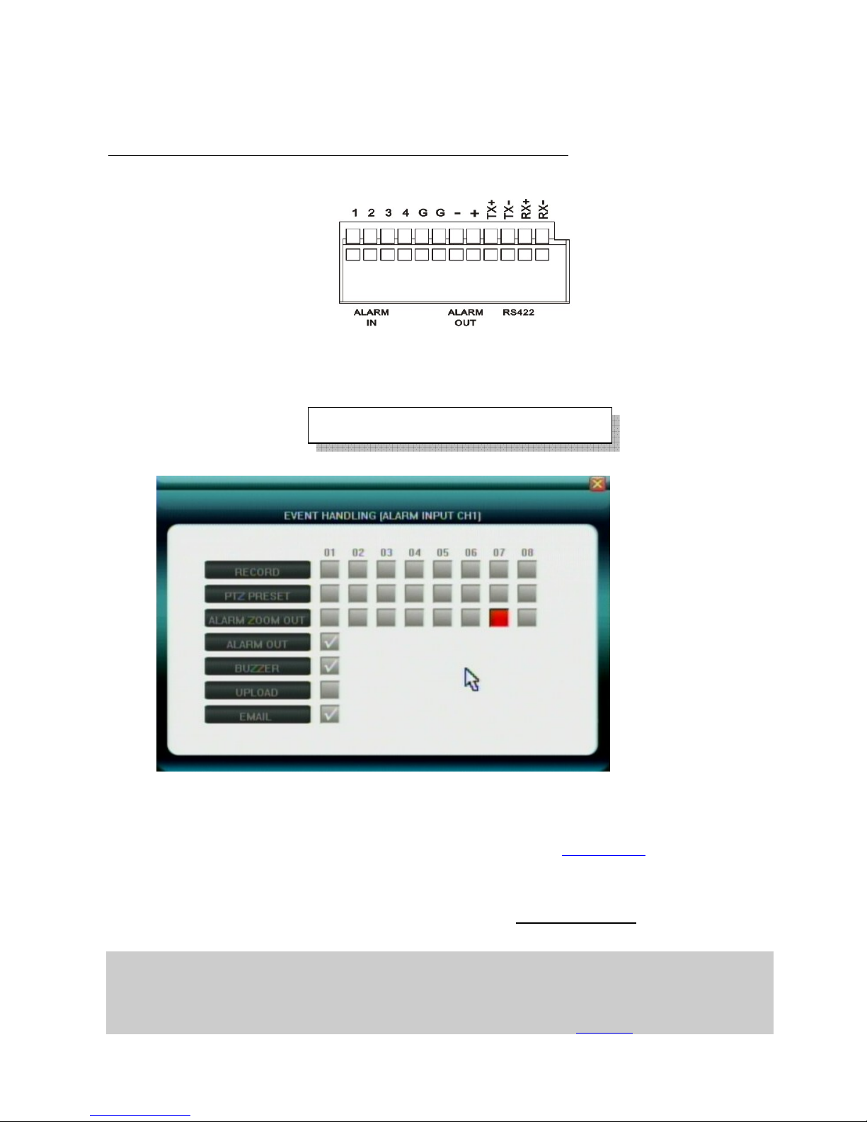
z Select alarm input channel for apply record setting. Select [ALL] for apply to all channels.
5.6.2 Alarm Input Type
The alarm input attribution includes N/O. and N/C.
Each camera has one input pin on Terminal Block at the real panel.
User must use voltage output type sensor to connect alarm input interface
Sensor device output POSITIVE (+) pin connect to DVR’s input pin (1~4 pin)
Sensor device output GROUND (-) pin connect to DVR’s G pin (5~6) pin
.
N/O.: Normally open. Sensor must constant output low level voltage. If output voltage change from Low
level to High level then DVR will be triggered.
N/C.: Normally connected. Sensor must constant output High level voltage. If output voltage change from
High level to Low level then DVR will be triggered.
Maximum high level voltage is 5VDC
5.6.3 Event Handling
User can pre-define correspond actions while DVR handling the Alarm event.
z Record: Start record immediately for selected channels
z PTZ PRESET: set up the PTZ preset position for selected channels
z Alarm Zoom Out: Set the pop up selected channels, please refer to Chapter 5.6.4
z Alarm Out: Set the Alarm output enabled
z Buzzer: Set the internal Buzzer enable
z Upload: upload these events message to IE or CMS server, to be displayed at the top right corner
z E-mail: Send E-mail with Snapshot picture(please refer to 5.5.6 E-mail Server
the E-mail address list)
Note1: if user wants to set alarm triggered record, please set the record schedule first at “Record Schedule”.
Note2: if user wants to set alarm triggered PTZ, please select the channel number first, and then to set (only preset 1 can be selected)
Note3: Event handling sound / report to alarm center need to be set in IE explorer. Please refer to Chapter 6.3
- 38 -
about how to set up
Page 40
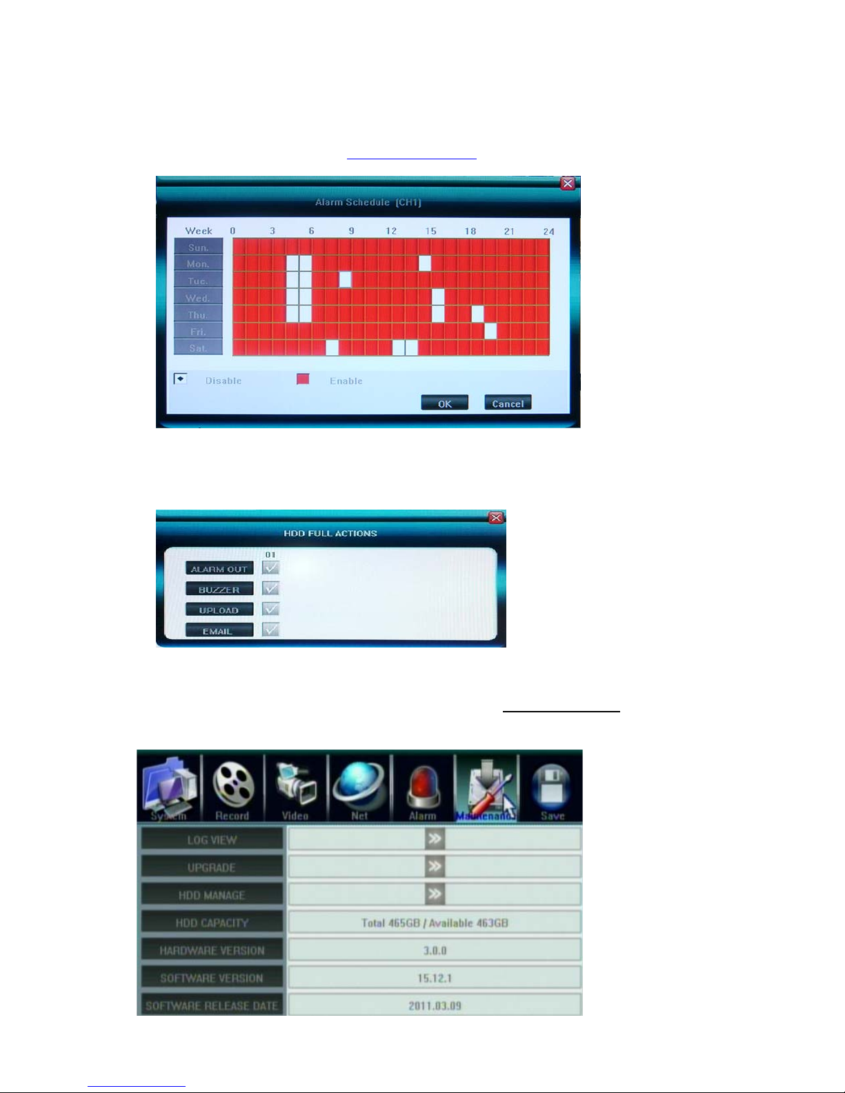
5.6.4 Alarm Setting(Schedule), Zoom Out and Hard Disk Full actions
ALARM SETTING - Alarm Schedule
Click 〖>>〗to open sub window for alarm schedule setting.
User can enable/disable alarm output by weekly schedule, the unit is hour, enable is red, disable is
white. There are mouse/faceplate buttons/remote control operations for set up as well, same as
record schedule, you can refer to 5.3.2 Record Schedule for details
Please note Motion/Alarm Schedule recording dose not compliant to Motion/Alarm event(action)
schedule
Alarm Zoom Out
Set the time interval(seconds) for channels pop out display while alarmed(Motion and Sensor)
Hard Disk Full actions
z Alarm Out: Set the Alarm output enabled
z Buzzer: Set the internal Buzzer enable
z Upload: upload these events message to IE or CMS server, to be displayed at the top right corner
z E-mail: Send E-mail with Snapshot picture(please refer to 5.5.6 E-mail Server
the E-mail address list)
about how to set up
5.7 Maintenance
- 39 -
Page 41
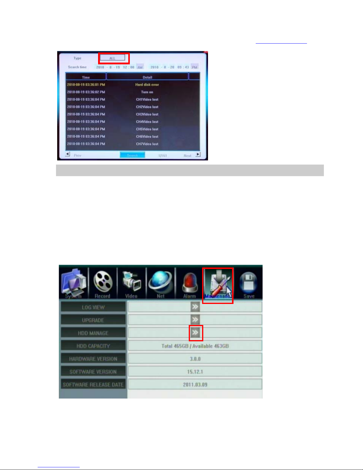
5.7.1 Log View
1. Select the type of log to be searched: All/ Operation/ Exception/ Alarm.
2. Select the time scope to be searched(it will display AM/PM if select correct Time Display format
3. Click Search to display the detail information of log.
Note: The maximum number of logs supported currently is 3000. The storage mode adopts overwrite mode: continuously overwrite
the oldest data when the database is full.
5.7.2 Software Upgrade
)
The upgrade modes supported now are USB & IE Remote Software:
USB:Please make sure the USB device is connected correctly and the upgrade applications have already being
copied into USB root directory. We suggest to use fresh USB Flash Disk for upgrade to prevent crash,
Please follow the prompts to operate. After accomplishing upgrade, press confirm button to restart.
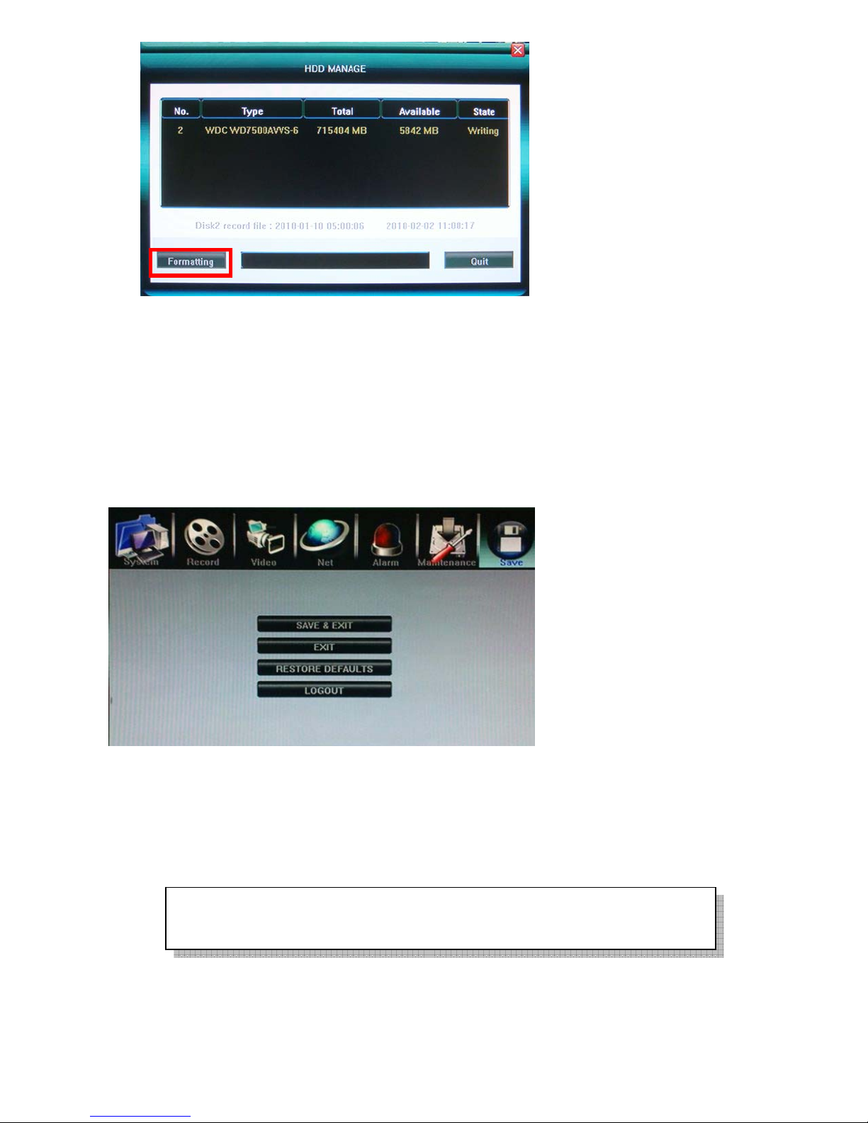
5.7.3 HDD Manage
HDD must be formatted by DVR before start recording audio/video.
Click 〖>>〗to open sub window and format the HDD by DVR.
HDD information will display on the windows if DVR detection HDD correctly.
Click 【Formatting】to start HDD format.
- 40 -
Page 42
5.7.4 HDD Capacity
Show DVR current HDD capacity status.
5.7.5 Hardware Version
Show DVR current hardware version.
5.7.6 Software Version
Show DVR current software version.
5.7.7 Software Release Date
Show DVR current software release date.
5.8 Save Setting
5.8.1 Save & Exit
Save all setting and exit menu.
5.8.2 Exit
Exit menu without save setting.
5.8.3 Restore defaults
Reset all configuration to factory default
The system language, time, camera PAL/NTSC system, and network settings (IP
address, subnet mask, gateway, HTTP port) will not be recovered by restoring to
factory defaults.
5.8.4 Logout
Save all setting and exit menu.
- 41 -
Page 43
6. Web Browser Operation(IE Browser only)
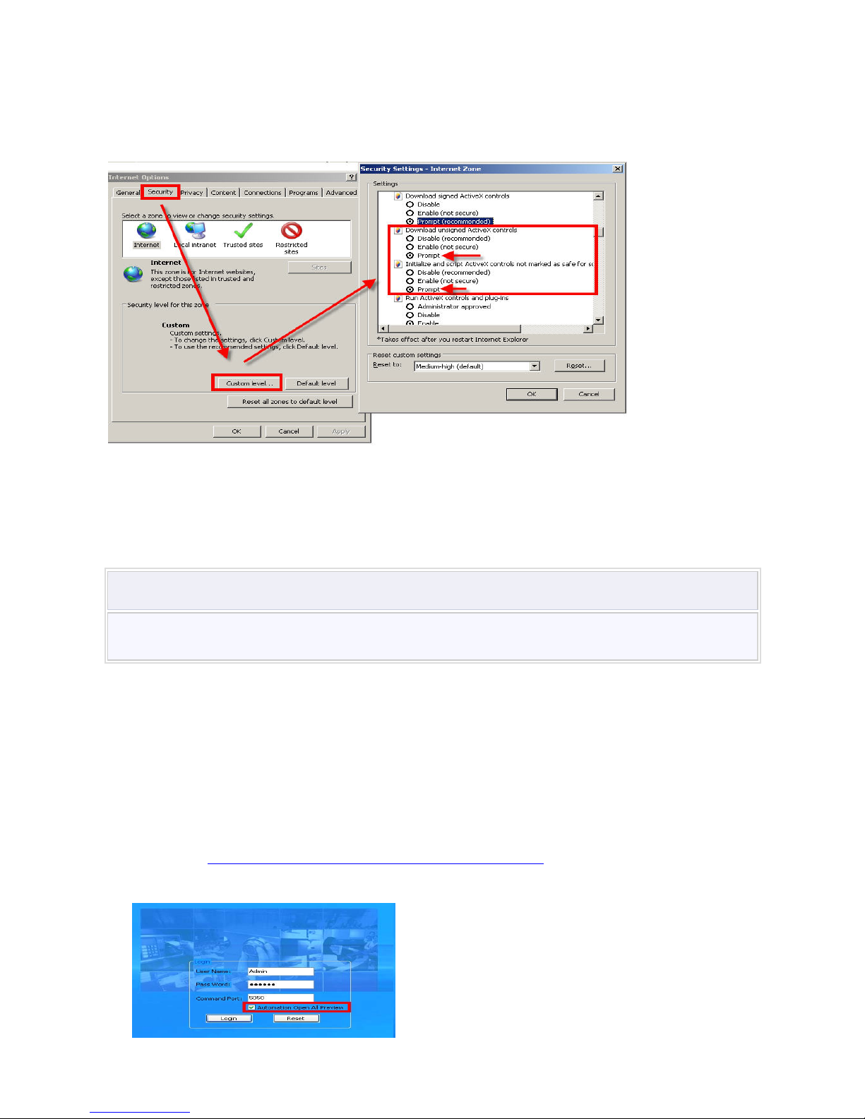
6.1 Enable Download Un-singed ActiveX Control if necessary
User’s computer need download ActiveX components for web access at the first time connect to DVR. If
user’s Internet explorer prohibits the download action(the DVR software is unsigned) then please manually
enable the download of un-signed ActiveX in IE.
Download unsigned ActiveX controlsÆ Enable or Prompt
Initialized and script ActiveX controls not marked as safe Æ Enable or Prompt
6.2 Turn off UAC for Windows 7 and Vista
To prevent unexpected troubles by ruing IE or CMS, we strongly suggest to disable UAC(User Account Control)
for Windows 7 and Vista. To perform the following procedure, you must be able to log on with or provide the
credentials of a member of the local
Important
Turning off UAC reduces the security of your computer and may expose you to increased risk from
malicious software. We do not recommend leaving UAC disabled.
To turn off UAC
1. Click
2. In
3. In the
4. In the
5. If UAC is currently configured in Admin Approval Mode, the
6. Clear the
7. Click
Source info: http://technet.microsoft.com/en-us/library/cc709691.aspx
Start
Control Panel
User Accounts
User Accounts
Click
Continue
.
OK
Restart Now
tasks window
, and then click
, click
.
Use User Account Control (UAC) to help protect your computer
to apply the change right away, or click
6.3 Web Browser Main Screen
Open IE browser, input IP address of the DVR, the Login windows will appear.
Administrators
Control Panel
User Accounts
window, click
tasks window, click
User Accounts
group.
.
.
.
Turn User Account Control on or off
User Account Control
Restart Later
.
message appears.
check box, and then click
and close the
User Accounts
- 42 -
Page 44
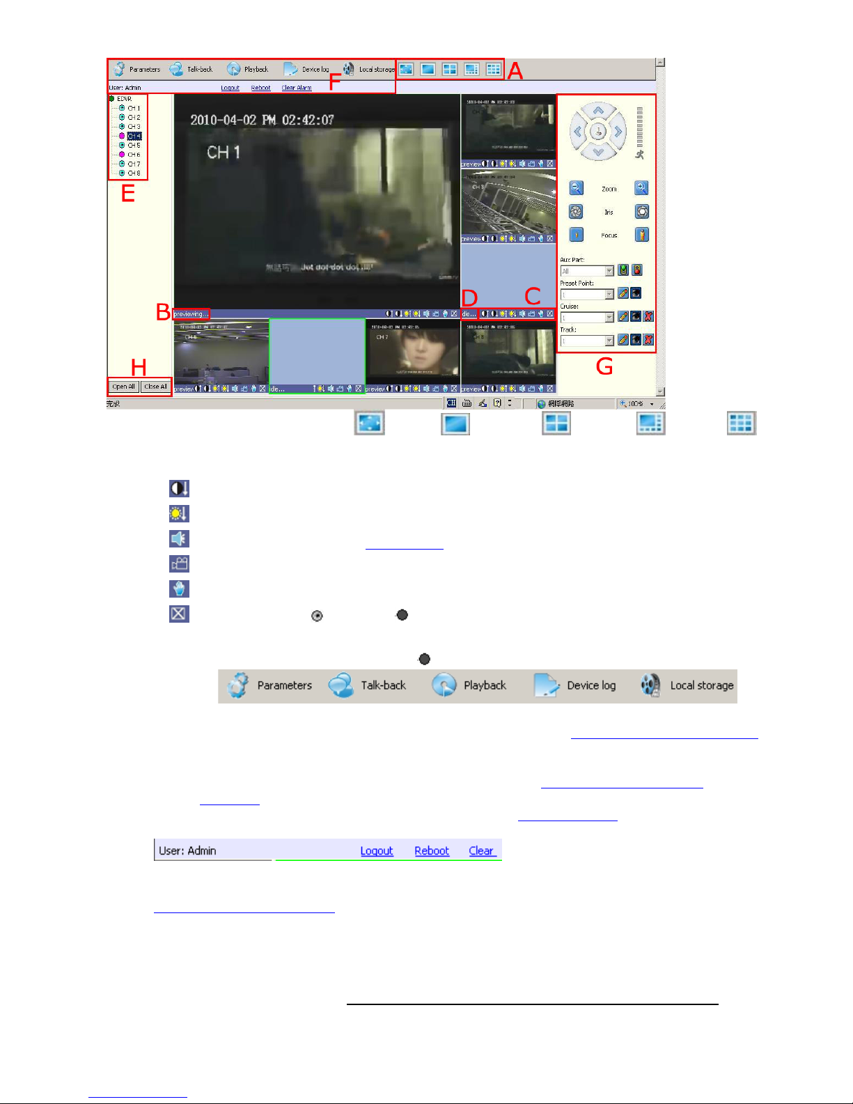
Check “Automation Open All Preview” to watch all cameras after login.
A. Camera view window: Full Screen /1 camera / 4 cameras / 8 cameras /9 cameras
B. Camera view is previewing
C. Camera view tools
:Adjust image contrast up/down.
:Adjust brightness up/down.
:Start/stop voice monitoring(Chapter 5.3.5). The icon will turn to green when recording.
:Start/stop recording. The icon will turn to green when recording.
:Click to snapshot.
:Stop preview, the will turn to on the E Available Camera list
D. Camera view is idle if not opened
E. Available Camera list: double right-click the to open the channel
F. Tools Bar
The description of icons from left to right is:
z Parameters: configure device parameters(set up), please refer to 6.5 Device Parameters Settings
z Talk-back: use channel 1 only, please open PC microphone and speakers, and DVR need to
connect active microphone/speaker
z Playback: Search and playback record files, please refer to 6.6 Video Files Playback &
Download
z Device log: View logs and export them, please refer to 6.6.3 Device Log
z Local storage: Set the storage directory of record files and pictures captured
From left to right: Current Login Account, Log-out, Restart DVR remotely, Clear alarm
G. PTZ Control
Please refer to 4.8 PTZ Control
H. Open All/Close All: open or close all the channel preview
6.4 Alarm Notification
When network connection is broken or abnormal, the alarm notification of “No heartbeat of device,
please check the network!” will be displayed in the right up side of the main screen
recovery of network, the preview will be displayed automatically.
. After
- 43 -
Page 45
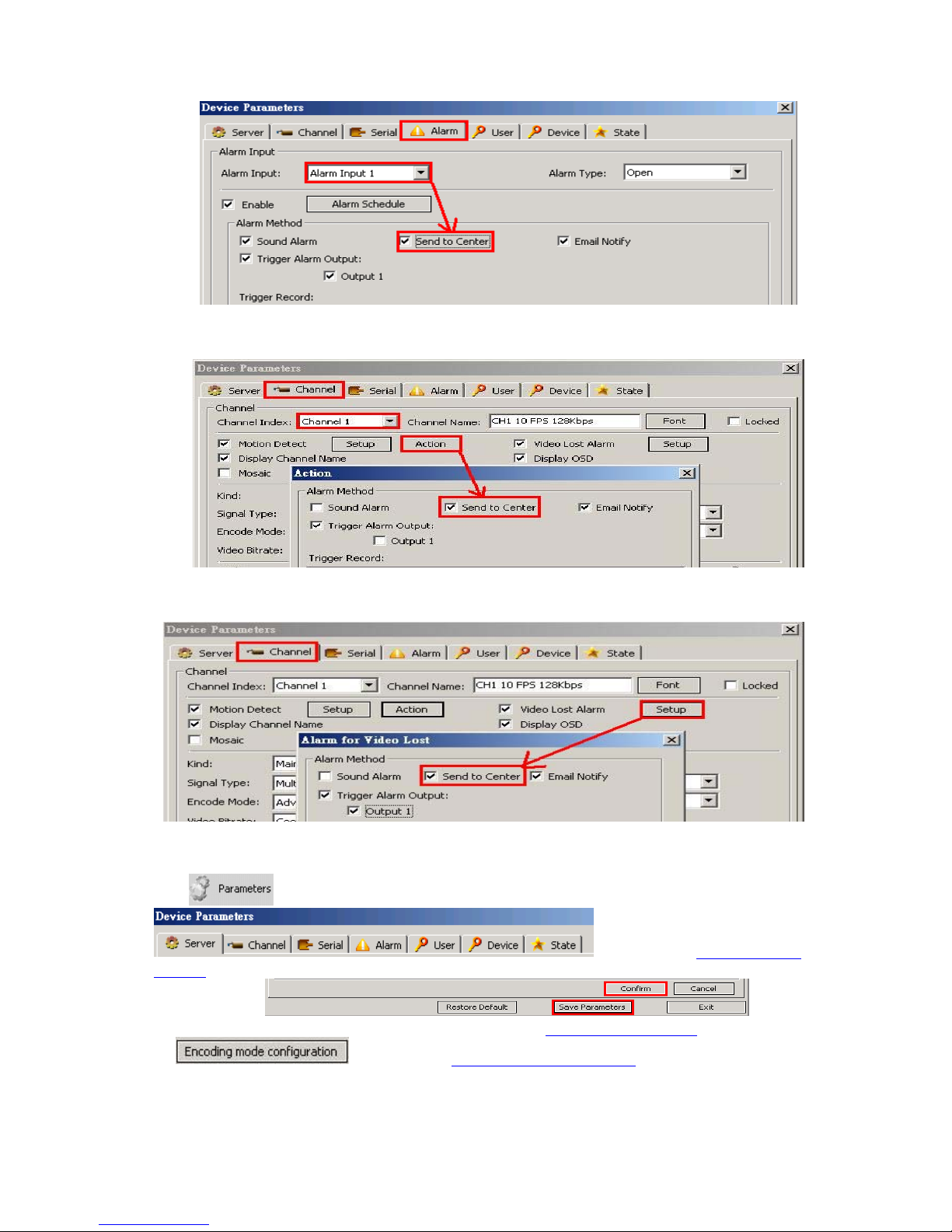
When alarms of remote notification occur, the alarm notification with alarm input number contained
such as “Device alarm: IO alarm, IO input x” will be displayed in the right up side of the main
screen. Enable this function in Device Parameters setting.
When alarms of motion detection with remote notification occur, the alarm notification with the alarm
channel number contained such as “Device alarm: motion detect ion, channel X” will be displayed in
the right up side of the main screen.
When alarms of video loss with uploading to center occur, the alarm notification with the alarm
channel number contained such as “Device alarm: video loss, channel x” will be displayed in the
right up side of the main screen.
6.5 Device Parameters Settings
Click , the Device Parameters will appear
Settings as well. After settings, please click “Confirm” and “Save Parameters” to be effective for each
setting window:
ServerÆNetwork setting, video system – please refer to Chapter 5.5 Net Setting
, please refer to Chapter 5 DVR
, please refer to 5.2.9 Resource Management
- 44 -
as well, for
Page 46
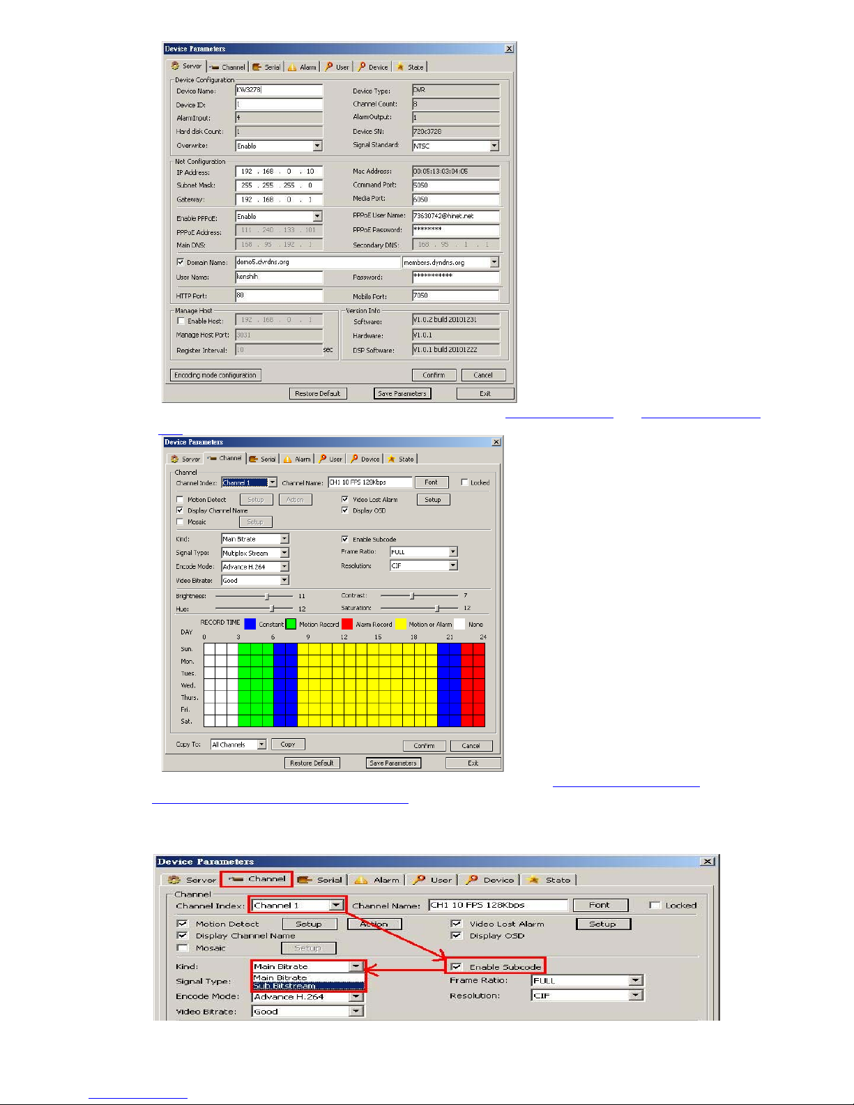
ChannelÆ Camera setting, Record setting – please refer to 5.3 Record Setting
well
and 5.4 Video Setting as
ChannelÆ Camera setting, Sub Bitstream, Subcode – please refer to 5.3.8 Dual Streaming for
Network(Record- Advanced Setting) as well
For limited upload bandwidth of internet that DVRs connect, or limited streaming capability of some
mobile phone/PDA, you have to adjust bandwidth of DVR to internet: [Enable Subcode] ->[Sub
Bitstream] ->[Video Bitrate]
- 45 -
Page 47
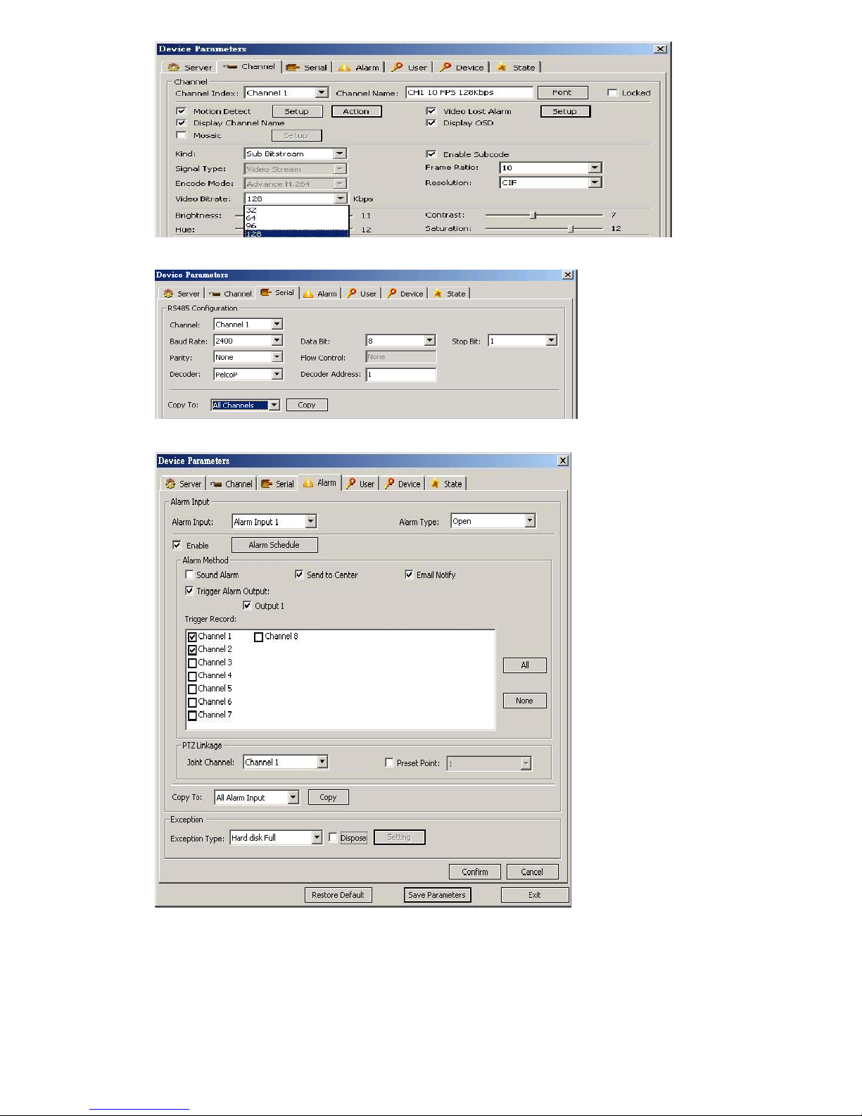
SerialÆPTZ Setting
AlarmÆ alarm input / output setting and HDD full action
DeviceÆFirmware upgrade , time synchronize and E-mail Notify setup
- 46 -
Page 48
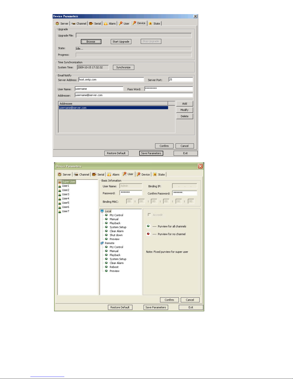
UserÆUser account and authority setting
State – HDD capacity, Channel and Network status
- 47 -
Page 49
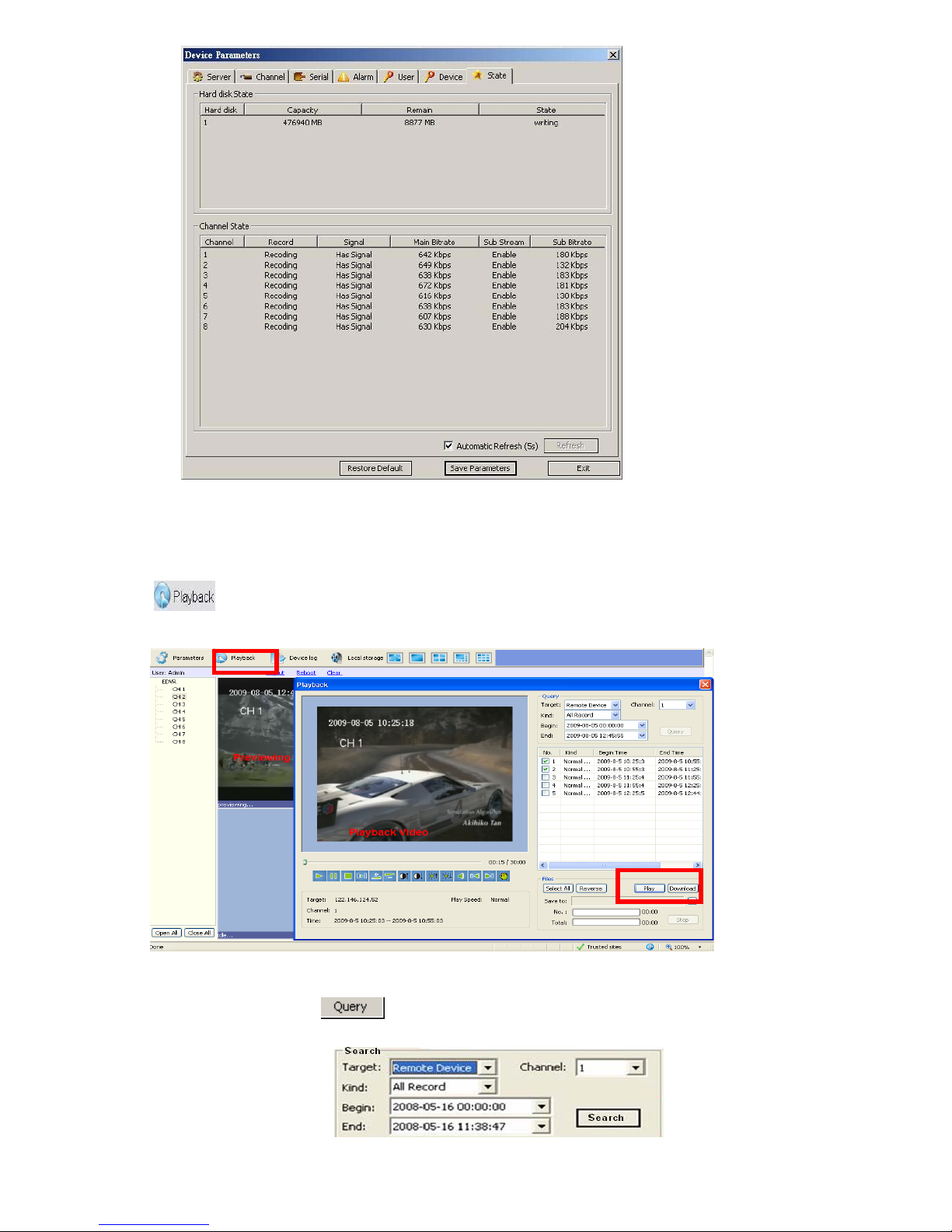
6.6 Video Files Playback & Download
6.6.1 Video Files Playback
Click , the playback screen will appear. It includes video files search, playback and video files
download.
Video Files Search
The file search part is on the right upper side of the screen, please set target, type, start time and end
time there. Then click
Specify the files in the table list and click on the playing control button or download button to do the
relevant operations.
to start searching. The result will list on the table.
- 48 -
Page 50
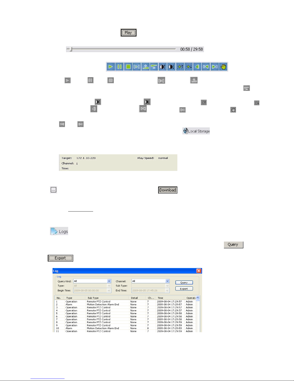
Video File Playback
The play control screen is on the left side of the screen. It includes image display area, play control bar,
and channel information. Click
progress of playing is shown as the figure below:
The playing control bar is shown as the figure below. The descriptions of all these icons from left to
right are as follows:
Play
playing will be doubled by each clicking. It includes: 2X, 4X, 8X, and 16X); Slow play option
current speed of playing will be half down by each clicking. It includes 1/2X, 1/4X, 1/8X, and 1/16X);
Enhance contrast
Open/close voice
; Pause ; Stop ; Go to next frame ; Fast play option (The current speed of
; Reduce contrast ; Enhance brightness ; Reduce brightness ;
; Go to previous file ; Go to next file ; Prompt file location
(
and is enabled only when multiple record files being selected to play); Snapshot (the
storage directory can be set on the pop-up screen by clicking
record file selected will be displayed in the area shown as the figure below. It includes device’s IP
address, current play speed, channel number and start/end time of the record file.
, the record files selected will be displayed in time order. The
(The
).The information of the
6.6.2 Download Video Files
Click to set the storage directory of the video file. Click to start downloading, the format is
MPEG4 or AVI, you may select.
Please refer to Chapter 4.6
for playback downloaded MPEG4 video by Windows Media player.
6.6.3 Device Log
Click , the screen of device logs will appear. There are four options for choosing: All, according to
time, according to type, according to time and type.
To search logs, please select the search mode and channel number needed first and then click
progress.
Click
to export logs in html format.
to
- 49 -
Page 51
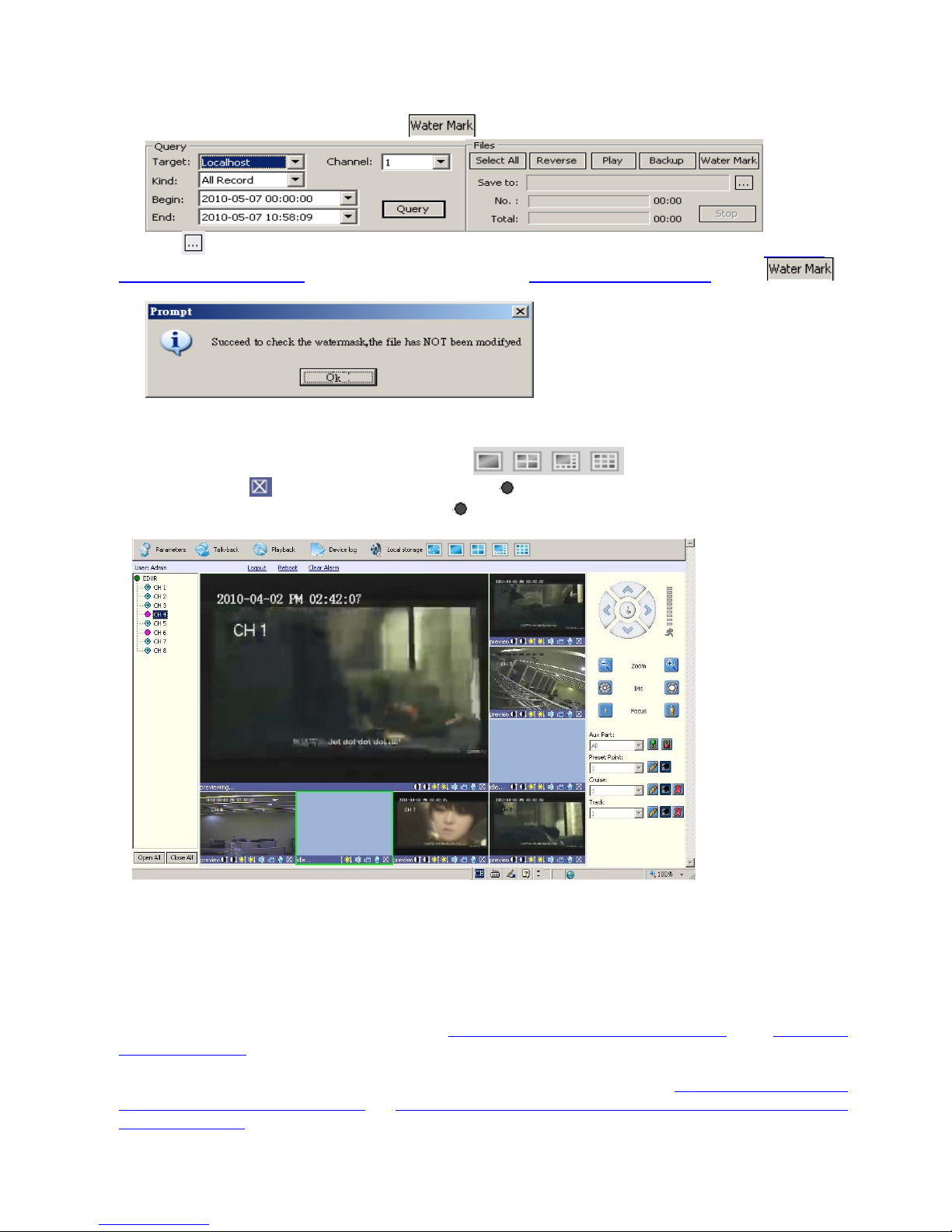
6.6.4 W ate r Mark Verification
All the record files for this DVR have watermark, but only MPEG4 format for verification. Select the “Local
host” from Target, you will find the find the
, click the
6.6.2 Download Video Files, or USB back up from local DVR(Chapter 4.6 Video Backup), Click
to verify it, then it will shown following if watermarked.
, to select the MPEG4 file from your PC, which may comes from Network back up as Chapter
shown up in the files Windows:
6.7 Channels allocation in Camera view window
When display some certain Camera view windows like , you can disable some channels
display by clicking
cursor to the fixed channel, and right click the pink
list(left side):
, and you can see it turns to be pink from camera list(left side), move the green
of the camera you want to display from the camera
7. 3G/3.5G Mobile Phone/PDA Support
Another state-of-the-art feature of this DVR device is transmitting live feed from the CCTV cameras to your
mobile phone, so that you can have an ‘on the go’ access to your surveillance system from virtually anywhere in
the world. Currently this feature is supported only for phones with the Windows Mobile, Nokia Symbian S60 3
and 5th Edition OS, Google Android, Black Berry OS 4.x and Apple iPhone 3G/3GS/iPhone 4/iPad.
To streaming from 3/3.5G mobile phone or PDA, you have to open the mobile port of DVR, the default setting is
7050, which may be changed, please refer to 5.5.5 PPPoE/DDNS(Net- Second Page]
Parameters Settings
For limited upload bandwidth of internet that DVRs connect, or limited streaming capability of some mobile
phone/PDA, you have to adjust bandwidth of DVR to internet, please refer to 5.3.8 Dual Streaming for
Network(Record- Advanced Setting) or 6.5 Device Parameters Settings - ChannelÆ Camera setting, Sub
Bitstream, Subcode (from IE) for more details
ServerÆNetwork setting, video system
- 50 -
rd/
or IE 6.5 Device
Page 52
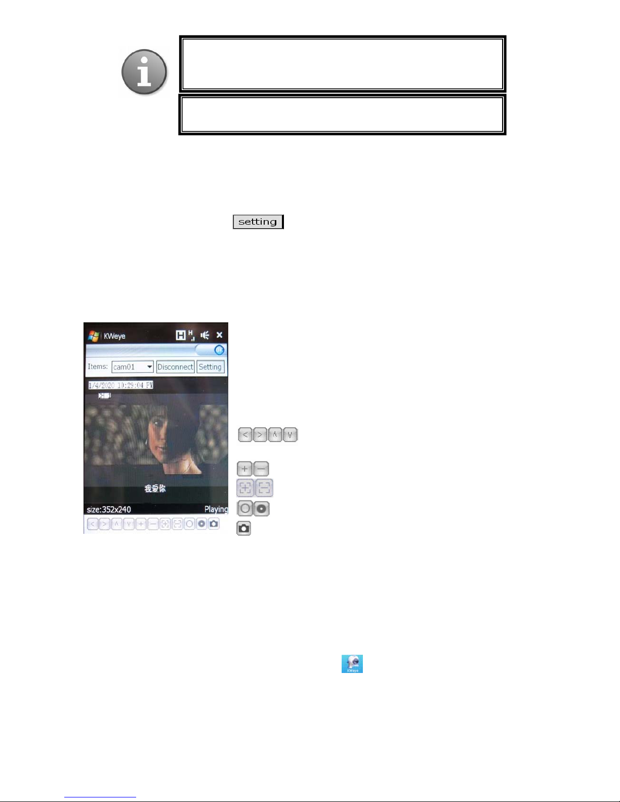
y
p
Note: Prior to using this feature, you should apply for the Internet
connection service for your mobile phone, such as 3G or 3.5G.
Please contact
our mobile service provi der for details.
You can only watch one live feed channel at a time with your
mobile
hone.
7.1 Windows Mobile
Open accessory CD and find the “amplayersetup.CAB” for the surveillance software.
Please refer to PDA user manual, copy *.cab into windows mobile pda
Double click on *.cab can start install software into PDA. After install completed, user can find QQEYE in the
application list.
Execute QQEYE program and click to setup IP address of remote DVR.
In the ensuing screen, input the Username (Admin), Password, and IP address(or DDNS) of your DVR (Server);
input the mobile Port no.(default 6003), and Notes for this DVR description; click the “OK” and “Auto
Connect” to save it and start to connect automatically; or click the “History” to choose one DVR that ever
connected.
The main window of the Mobile Phone application offers the choice of channels(Items), Disconnect/connect
and Settings buttons.
To connect to the system and start watching the live feed from your CCTV
cameras, click on the Connect button or Disconnect to stop watching
To choose the camera, use the Items dropdown menu.
To modify settings, press the Setting button.
On-screen data will provide information about current time (in the
MM-DD-YYYY HH:MM:SS format), Channel name, resolution, and
status of the camera.
The menu bar contains the following controls.
Directional buttons for controlling the direction of the
PTZ camera view
Zoom in / out
Focus
Iris
Snapshot
7.2 Nokia/Samsung/LG Symbian S60 3rd/S60 5th Phones
Open accessory CD and find the “KWeye_JH_3rd_1222.sisx”, or “KW eye_JH_5th1222.sisx” mobile
surveillance software according to Symbian OS S60 3
phone to install the software into mobile phone. While install the software, must set “software
installation -ALL”, and “Online Certificate check - off”, ex. Main menu --> Applications --> App.
mgr. (application management) --> Options --> settings --> software installation ,set ALL -->
Online Certificate check , set off
After installation is complete, please locate the KWeye
mobile phone.
Execute KWeye and the program window will appear on the screen.
rd
or 5th. Please refer to user manual of mobile
icon in the list of applications on your
- 51 -
Page 53
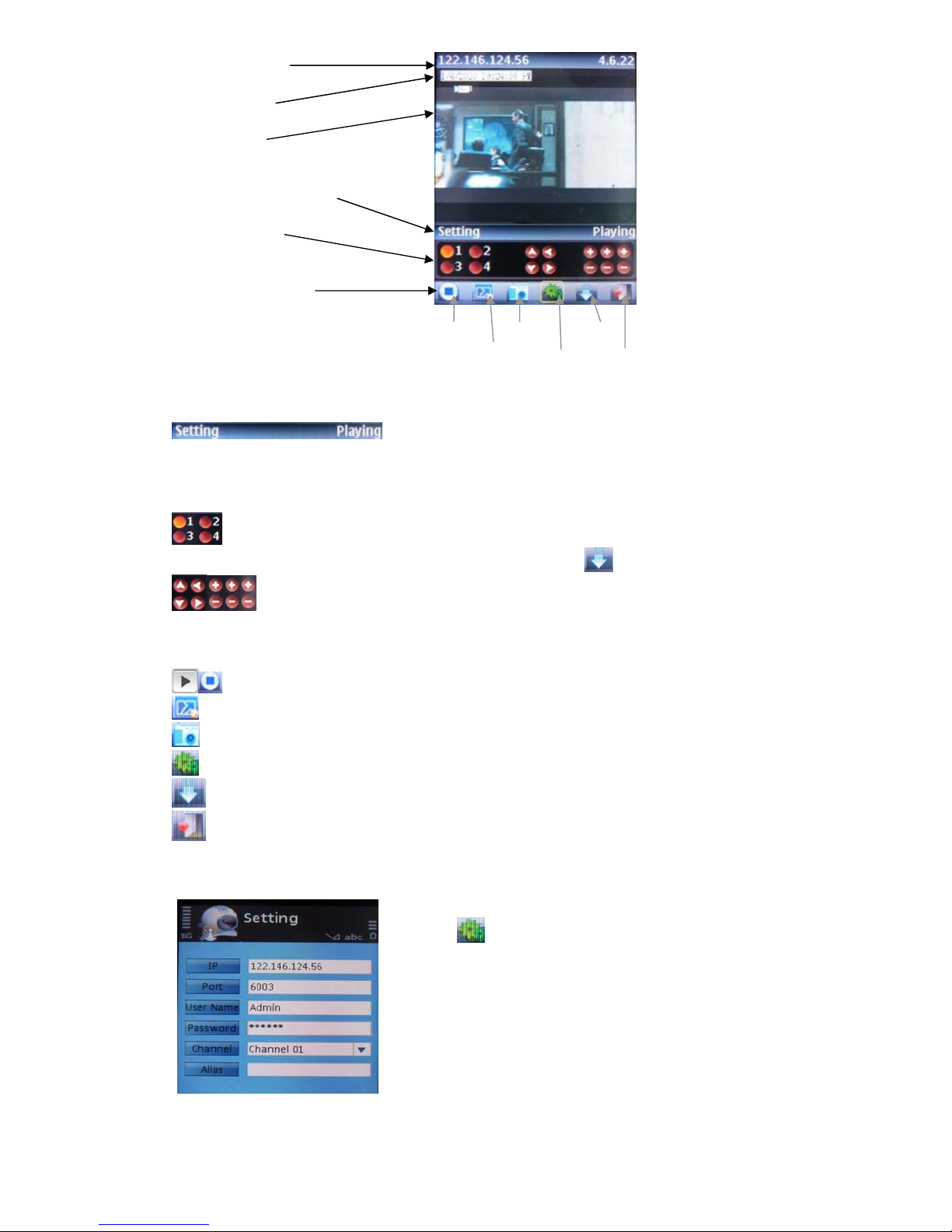
IP address line
Camera info.
Camera view
Status information line
Control buttons
Functional buttons
Play/Stop Snap Next
Full Mode Setting Exit
In order to navigate between the buttons, please use the directional keys of your Symbian mobile phone.
Explanation of the menu buttons and program interface:
Status information line. The first status tag indicates the name for the selected functional button in the
below control bar (in the illustration, it is “Setting”). The second tag word denotes the current status of
the program (in the illustration, it is “Playing”).
Control buttons:
Selection of channels. If your system supports 8 or 16 channels, to switch between channel
buttons 1-4, 5-8, 9-12, and 13 -16, please use functional button
PTZ camera direction controls, PTZ camera Zoom, Focus and Iris controls
Functional buttons:
When highlighting these buttons, the name of the corresponding function will be displayed in the status
information line (the first tag name).
Play / Stop button
Full Mode. Displays the camera feed in the full-screen mode. All menus and buttons will be hidden.
Snap. Allows you to take a snapshot of the camera view.
Setting. Brings up the connectivity setup screen.
Next Group. Toggling between other available 4-channel views: 1-4 and 5-8 or 9-12, 13-16
Exit KWeye
In order to start working with the CCTV feed on your Symbian mobile phone, you will have to
configure the program by entering the preferred network access point, IP address(or DDNS) of the DVR,
mobile phone port, username, and password.
Click the
In the Setting screen, enter the following data:
IPs: DVR IP address or DDNS
icon to enter the setup window.
(see below)
Channel: choose channel to connect first
Alias: description of this DVR
Port: Mobile Port [6003 by default]
User Name: Login User Name〖Admin〗
Password: Password [888888 by default]
- 52 -
Page 54

Mobile phone reference list for OS S60 3rd:
N
N
N
N
N
N
N
N
N
N
N
N
N
N
N
N
N
N
N
N
N
N
N
N
N
N
N
N
N
N
N
N
N
N
N
N
N
N
N
N
N
N
N
N
N
N
N
LG-KT610 S60 3rd_FP1 10-Feb-08
LG KS10 S60 3rd_FP1 09-Oct-06
LG-KT615 S60 3rd_FP1 30-Oct-08
okia 3250 S60 3rd_INIT 13-Sep-05
okia 5320 XpressMusic S60 3rd_FP2 22-Apr-08
okia 5500 Sport S60 3rd_INIT 09-May-06
okia 5630 XpressMusic S60 3rd_FP2 10-Feb-09
okia 5700 S60 3rd_FP1 29-Mar-07
okia 5730 XpressMusic S60 3rd_FP2 11-Mar-09
okia 6110 Navigator S60 3rd_FP1 08-Feb-07
okia 6120 S60 3rd_FP1 17-Apr-07
okia 6121 S60 3rd_FP1 18-Jun-07
okia 6210 Navigator S60 3rd_FP2 11-Feb-08
okia 6220 S60 3rd_FP2 11-Feb-08
okia 6290 S60 3rd_FP1 28-Nov-06
okia 6710 Navigator S60 3rd_FP2 16-Feb-09
okia 6720 Classic S60 3rd_FP2 16-Feb-09
okia E51 S60 3rd_FP1 18-Sep-07
okia E55 S60 3rd_FP2 16-Feb-09
okia E60 S60 3rd_INIT 09-Oct-05
okia E61 S60 3rd_INIT 09-Oct-05
okia E61i S60 3rd_INIT 10-Feb-07
okia E62 S60 3rd_INIT 09-Sep-06
okia E63 S60 3rd_FP1 12-Nov-08
okia E65 S60 3rd_INIT 09-Feb-07
okia E66 S60 3rd_FP1 16-Jun-08
okia E70 S60 3rd_INIT 09-Oct-05
okia E71 S60 3rd_FP1 16-Jun-08
okia E75 S60 3rd_FP2 16-Feb-09
okia E90 S60 3rd_FP1 11-Feb-07
okia N71 S60 3rd_INIT 09-Nov-05
okia N73 S60 3rd_INIT 09-Apr-06
okia N75 S60 3rd_INIT 27-Sep-06
okia N76 S60 3rd_FP1 08-Jan-07
okia N77 S60 3rd_INIT 12-Feb-07
okia N78 S60 3rd_FP2 11-Feb-08
okia N79 S60 3rd_FP2 21-Aug-08
okia N80 S60 3rd_INIT 09-Nov-05
okia N81 S60 3rd_FP1 29-Aug-07
okia N81 8GB S60 3rd_FP1 29-Aug-07
okia N82 S60 3rd_FP1 14-Nov-07
okia N85 S60 3rd_FP2 21-Aug-08
okia N86 8MP S60 3rd_FP2 17-Feb-09
okia N91 S60 3rd_INIT 14-Apr-05
okia N92 S60 3rd_INIT 09-Nov-05
okia N93 S60 3rd_INIT 09-Apr-06
okia N93i S60 3rd_INIT 08-Jan-07
okia N95 S60 3rd_FP1 26-Sep-06
okia N95 8GB S60 3rd_FP1 29-Aug-07
okia N96 S60 3rd_FP2 11-Feb-08
Samsung I7110 S60 3rd_FP2 20-Oct-08
Samsung INNOV8 S60 3rd_FP2 25-Jul-08
Samsung SGH-G810 S60 3rd_FP1 11-Feb-08
Samsung SGH-i400 S60 3rd_FP1 26-Apr-07
Samsung SGH-i450 S60 3rd_FP1 14-Oct-07
Samsung SGH-i520 S60 3rd_FP1 09-Oct-06
Samsung SGH-i550 S60 3rd_FP1 15-Oct-07
Samsung SGH-i560 S60 3rd_FP1 16-Oct-07
Samsung SGH-L870 S60 3rd_FP2 28-May-08
Symbian OS S60 5
th
Mobile Phone – Nokia 5800XM, N97, 5230, 5802XM, 5530XM and x6
Back to the main window, and press the button to connect
to the DVR. After your device successfully logs in to the DVR,
you can watch the remote video feed on your Symbian mobile
phone.
- 53 -
Page 55
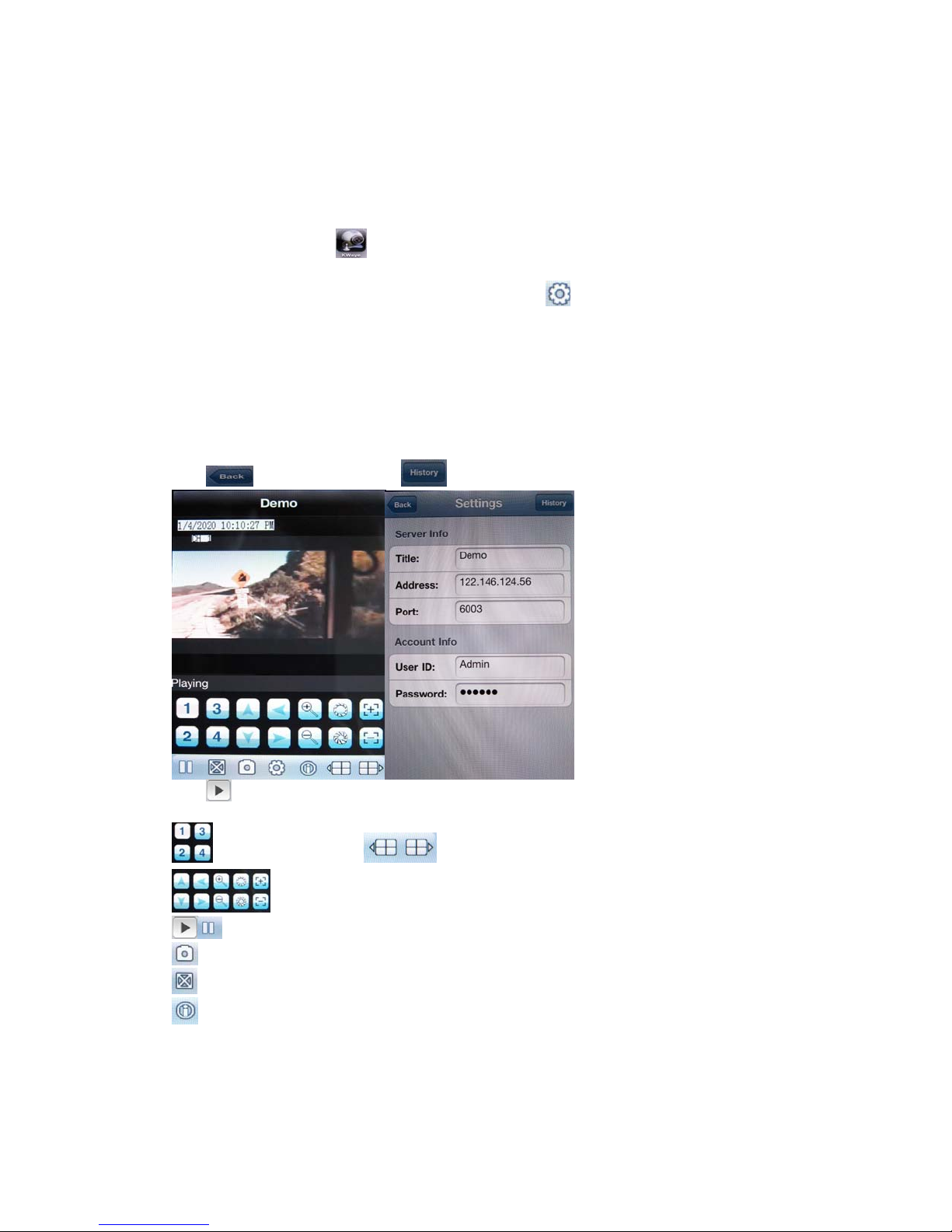
7. 3 iPhone/iPad Series
Please use 2nd generation iPhone3GS/iPhone4 or iPad , this Apple application, like all iPhone/iPad
application, needs to be downloaded directly from the iPhone/iPad AppStore.
1) Open Apple iTunes
2) Search for “KWeye” from our third party supplier. It will be a free application.
3) Download and install onto iPhone as per iPhone installation procedures.
4) Please locate the icon and click on it to open the application.
5) You will see following screen.
6) To set up the connection to the DVR, please first click icon to enter settings menu as below right
screenshot:
Server Info.
Title: Description of this DVR
Address: DVR IP address or DDNS
Port : Mobile Port [6003 by default]
Account Info.
User ID: Login User Name〖Admin〗by default
Password: Password [888888 by default]
Click
Click icon to connect DVR immediately, after login DVR successfully, user can watch the remote
video from mobile phone; the other icons function are as follows:
Picture Snapshot.
after setting, or click to choose other DVR that ever connected.
switch channel,click show another 4 channel list
Control PTZ camera direction, Zoom, Iris and Focus.
Play / Stop button
Full Screen
This software information
- 54 -
Page 56
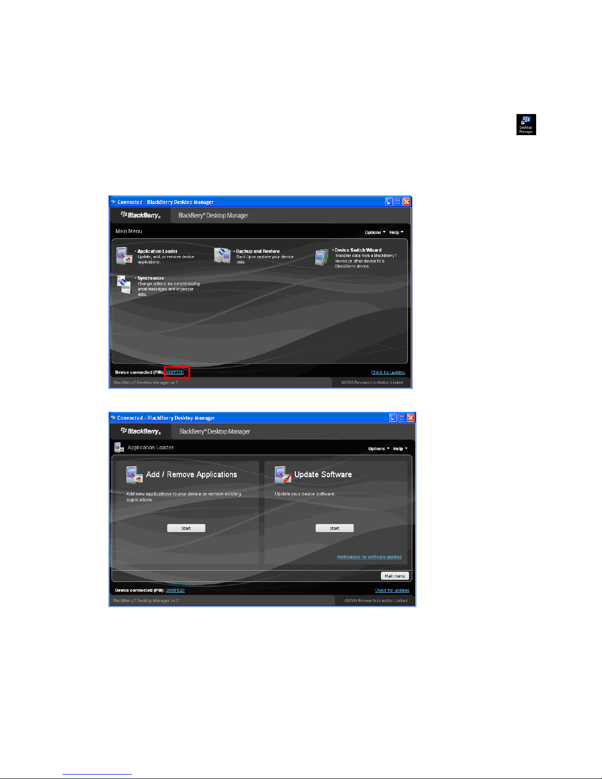
7. 4 Blackberry Series
1) Program installation
1. Open accessory CD and copy the setup software “KWeye.cod” and “KWeye.alx” to your PC.
2. In order to be able to install applications and themes via BlackBerry Desktop Manager, firstly the PC
should install Blackberry Desktop Manager. BlackBerry Desktop Manager will be known as “DM.”
otherwise the phone cannot establish the connection with the PC.
3. Connect your BlackBerry mobile phone to your computer via the USB cable that came with it, or any
USB cable that fits. Start the DM.
4. Before the installation, open the BlackBerry Desktop Manager. Shown as the red sign on the
following pictures, which means the phone has been connected to the PC.
5. Click on “Application Loader” to enter into its interface. In this screen you have two options to select
from. Select “Add/Remove Applications” (shown as follows) to Start
;
6. You should now see something like what you see below. From this screen, click “Browse” (shown as
follows).
- 55 -
Page 57
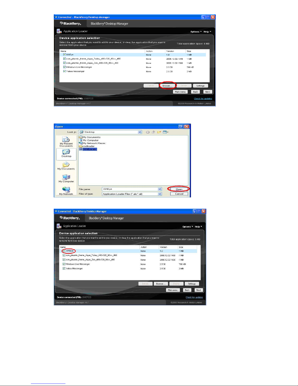
7. Once you click “Browse” you will see a file search screen like the one below. Go to and locate where
you saved the application files. Make sure you saved both the “.alx” file and “.cod” file in the same
folder. After finding the “KWeye.alx” file for the application, highlight it and click “open”.
8. You will now return to the Application Loader screen. From here you should see “KWeye” now listed
with Install under the Action column (shown as follows) if the installation is successful.
9. You can remove the program “KWeye” as the following method. To enter into Application Loader
screen, on “Device application selection” you can select the application that you want to clear from your
device. When the option “Action” is “Remove”, it means the program will be clear from your device.
- 56 -
Page 58
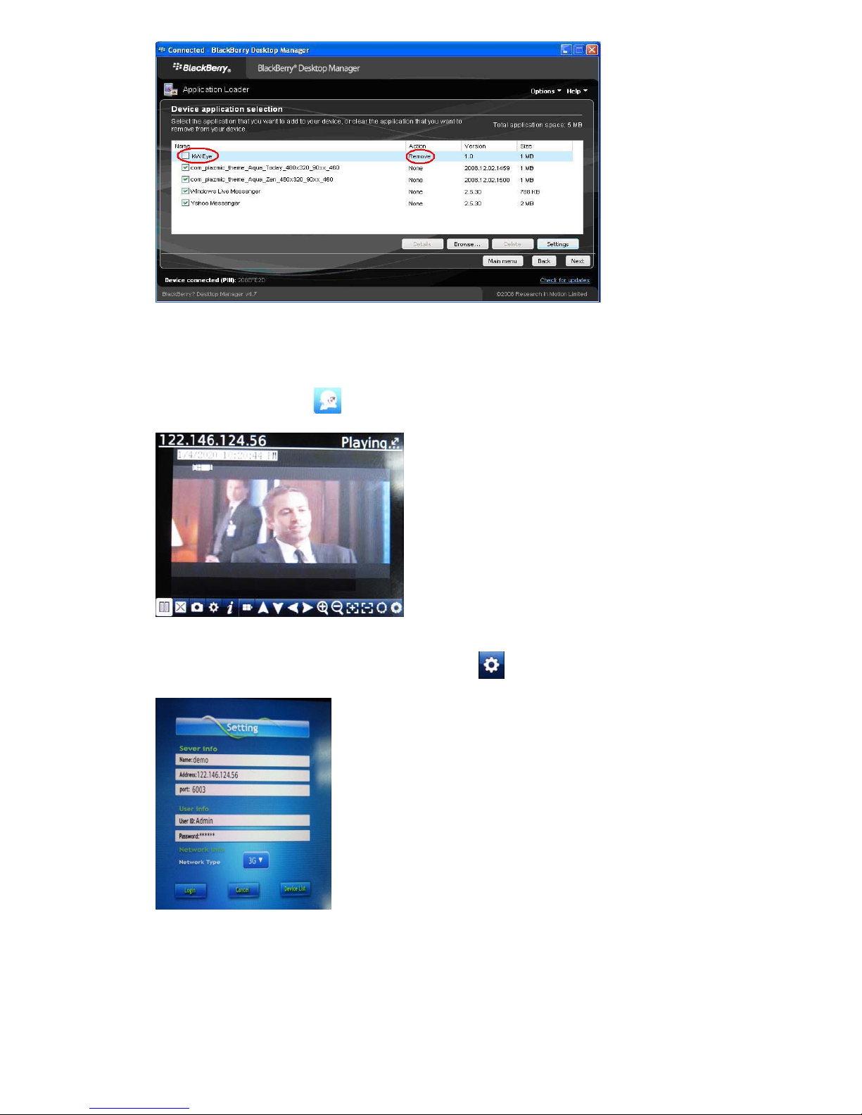
2) System explanations
KWeye phone port has the following capabilities and functions: live video surveillance, channel switch,
full screen display, PTZ control, including zoon/focus/iris, image capture, save as favorite and exit
function.
① System main interface
After the installation, press
“KWeye” icon in the application, it will appear the below picture(The
Main page)
② System setting
To set up the connection to the DVR, please first click
screenshot:
icon to enter settings menu as below right
Server Info.
Name: Description of this DVR
Address: DVR IP address or DDNS
Port : Mobile Port [6003 by default]
User Info.
User ID: Login User Name〖Admin〗by default
Password: Password [888888 by default]
- 57 -
Page 59
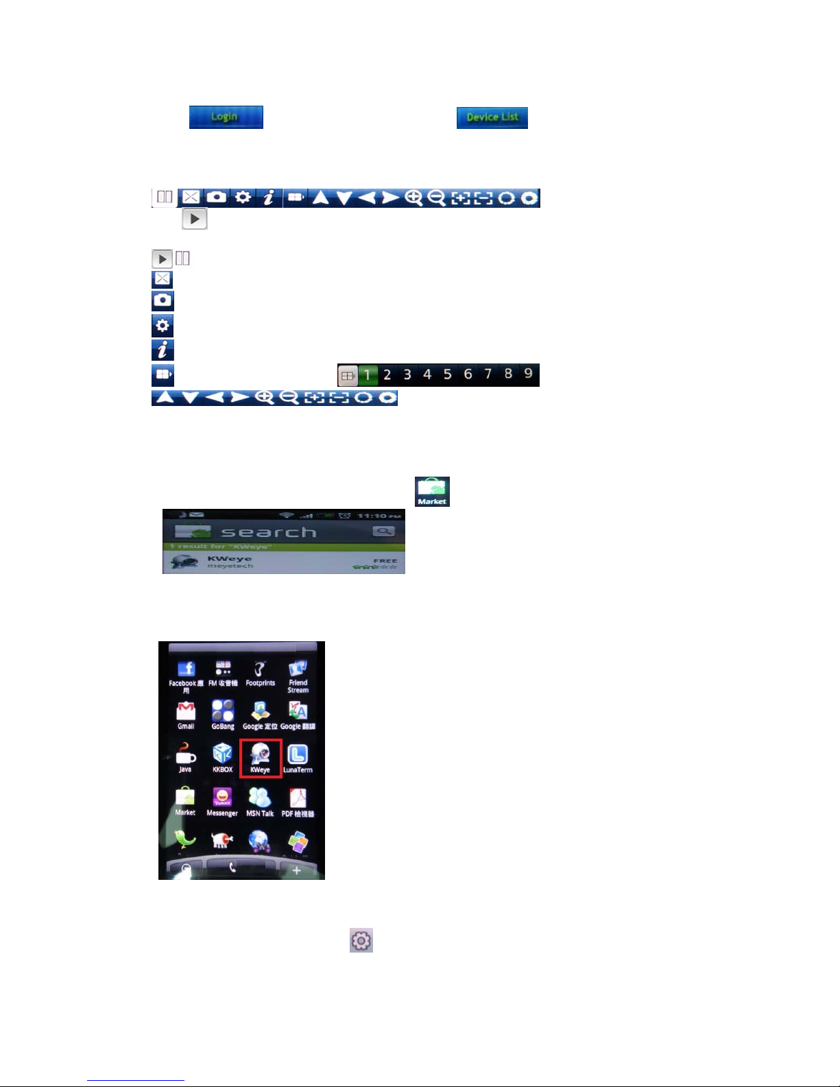
Network Info.
Network Type: Network through which you connect to the internet, like 3G, WiFi or others
Click
after setting to connect, or click to choose other DVR that ever set up
for streaming.
③ Function buttons
Click
icon to connect DVR immediately, after login DVR successfully, user can watch the remote
video from mobile phone; the other icons function are as follows:
Play / Stop button
Full Screen
Picture Snapshot
DVR settings
This software information
Click to choose channel list
Control PTZ camera direction, Zoom, Iris and Focus.
7. 5 Android Mobile (Google Phone compatible)
1. Software Installation
1.1 Please go to Andord sofwtare market
to search “KWeye” as below:
, click to enter and start to “Install”; or copy the software
“KWeye.apk” from the CD:/Mobile Phone software/Android to the Android phone(SD card) to
install.
1.2 After installed successfully, it will appear KWeye icon in the “All appas”:
2. Software Operation
2.1 After the installation, click the “KWeye” icon in the “All appas” to run, it will show the main
page as left phot, click the Settings
, it will show the right photo:
- 58 -
Page 60
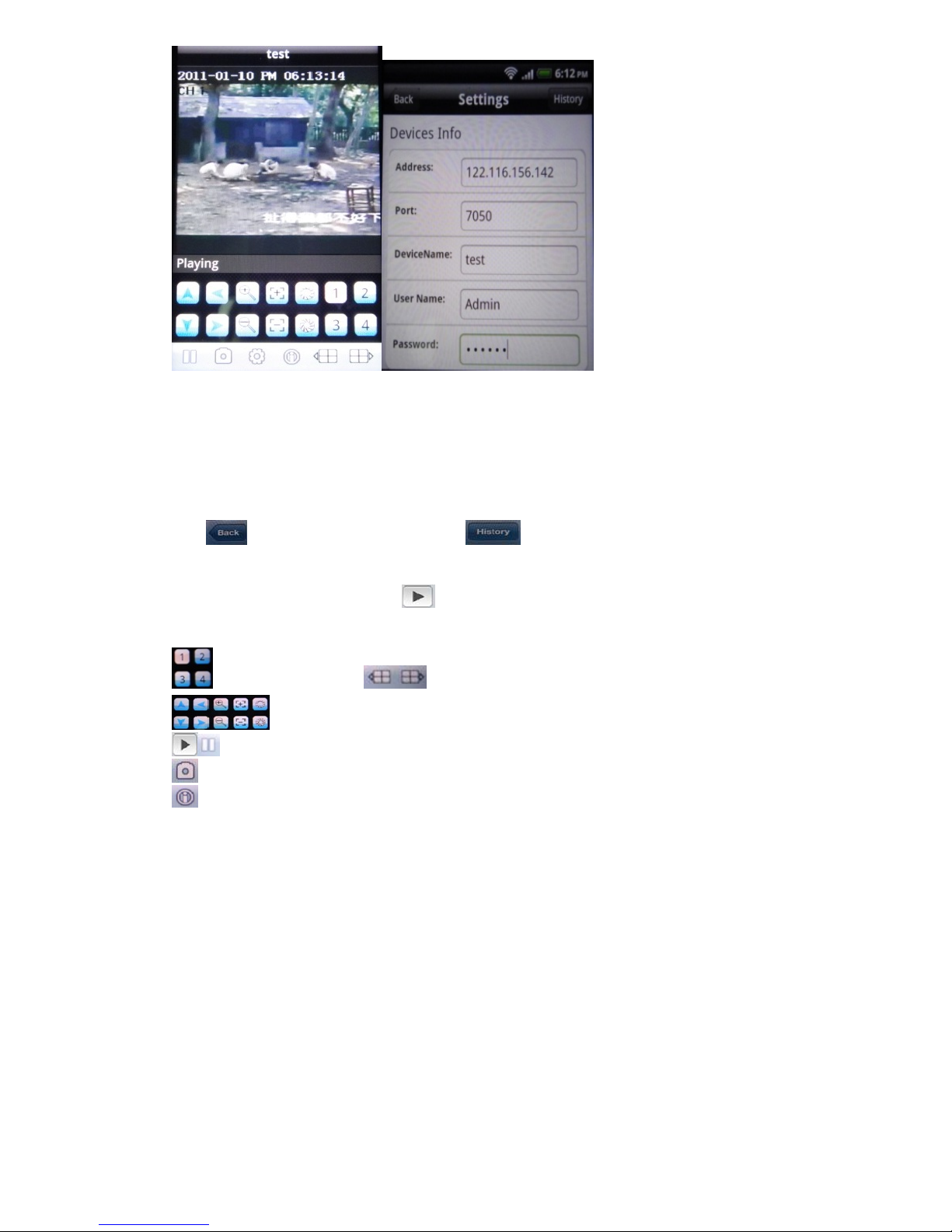
2.2 System Settings:
As the right photo for last page, you may set up the parameters as below:
Devices Info.:
Address: DVR IP address or DDNS
Port : Mobile Port [6003 by default]
DeviceName: Description of this DVR
User Name: Login User Name〖Admin〗by default
Password: Password [888888 by default]
Click
after setting to connect, or click to choose other DVR that ever connected.
2.3 The main display screen:
As the left photo for last page, click
icon to connect DVR immediately, after login DVR
successfully, user can watch the remote video from mobile phone; the other icon functions are as
follows:
switch channel,click to show another 4 channel list
Control PTZ camera direction, Zoom, Iris and Focus.
Play / Stop button
Picture Snapshot.
This software information
- 59 -
Page 61

8. Appendix
Appendix A-HDD Capacity/Recording Time Estimate
Calculate the maximum capacity of the build-in hard disk.
z Ti ming R ecording:
Step 1: Calculate the maximum capacity of the hard disk needed in selected channel per hour, suppose as Si
(MByte) (i is the channel number), and suppose the bit rate of the channel selected as D (Kbit/s). The formula
of calculation is:
Si =(D*3600)/(8*1024)= D * 0.439453125 MB
Step 2: Confirm the storage time length, suppose as T hours. The total maximum capacity of the hard disk
needed in selected channel for T hours, suppose as St is:
St = T * S1
Step 3: Confirm the total numbers of the channels, suppose as n. The total maximum capacity of the hard disk
needed, suppose as Sc is:
Sc = S1 + S2 + … + Sn
Record Quality
(Bit rate)
Frame Rate
(PAL/NTSC)
HDD Capacity
Recording Time(days)
4CH 8CH 16CH
Best(768Kbps)
15.8 7.9 3.9
High(640Kbps) 19.0 9.5 4.8
500GB
Middle(512Kbps) 23.7 11.9 5.9
Low(384Kbps) 31.6 15.8 7.9
Best(768Kbps)
23.7 11.9 5.9
High(640Kbps) 28.4 14.2 7.1
750GB
Middle(512Kbps) 35.6 17.8 8.9
Low(384Kbps) 47.4 23.7 11.8
Best(768Kbps)
High(640Kbps) 37.9 19.0 9.5
Full Frame
Rate(30 or 25
CIF = 15 or
12.5 Half D1 =
7.5 or 6 D1)
31.6 15.8 7.9
1000GB
Middle(512Kbps) 47.4 23.7 11.9
Low(384Kbps) 63.2 31.6 15.8
Best(768Kbps)
63.2 31.6 15.8
High(640Kbps) 75.9 38.0 19.0
2000GB
Middle(512Kbps) 94.8 47.4 23.8
Low(384Kbps) 126.4 63.2 31.6
Hard Disk capacity/recording time is only related to bite rate, neither Resolution, nor Frame rate
Calculate the compression bit rate for recording T hours.
z Ti ming R ecording
Step 1: Suppose the capacity of the hard disk as S, the total numbers of the channel as n. The capacity of hard
disk needed per channel supposed as Di is:
Di = S / n
Step 2: Suppose the total recording time as T hours. The capacity of the hard disk needed per hour per
channel supposed as Dt is:
Dt = Di / T
Step 3: The bit rate of all the channels supposed as Dc is:
Dc = Dt *(8*1024)/ 3600 = Dt * 2.2756 (Kbit/s)
- 60 -
Page 62

Appendix B– Compatible HDD List
The other brand or model, please test by yourselves
Item Model Number Size(GB) Drive
WD WD5001ABYS, WD5000AADS 500 SATA
WD WD5000AVVS, WD5000AVDS 500 SATA
WD WD7500AACS 750 SATA
WD WD10EADS, WD10EVDS, WD10EALS 1000 SATA
WD WD15EADS 1500 SATA
WD WD20EVDS, WD20EADS 2000 SATA
HITACHI HDS721050CLA362 500 SATA
HITACHI HDS721075KLA330 750 SATA
HITACHI HDT721010SLA360, HDS721010CLA332 1000 SATA
HITACHI HDS722020AL330 2000 SATA
Maxtor 6V16010 160 SATA
Seagate ST3250310SV 250 SATA
Seagate ST3500320SV, ST3500320AS, ST3500418AS 500 SATA
Seagate ST31000528AS, ST31000520AS 1000 SATA
Seagate ST31500341AS 1500 SATA
Seagate ST32000542AS, ST32000641AS 2000 SATA
Samsung HD161HJ 160 SATA
Samsung HD501LJ 500 SATA
Appendix C– Compatible USB portable DVD Burner List
The other brand or model, please test by yourselves
* Sony DRX-S70U-R
* HUGE USB Slim Portable Optical Drive
* LG GE20LU10
* Lite On eSAU108
* Buffalo DVSM-P58U2/B
Appendix D– Change Notice
None for the first printing version
- 61 -
Page 63

Samriddhi Automations Private Limited
Corporate Office: B - 118, Sector - 10, Noida, U.P. (India) Tel : + 91 - 120 - 4518 900 (20 Lines)
Works: Plot No. : 75, Sector - 7, I.I.E., SIDCUL, Haridwar (India) Tel : + 91- 01334 - 645 011, 239 396
Service Center: A - 1 / 15, New Kondli, New Delhi. (India) Tel : 91-11-2262 3325
[email protected] | www.sparshsecuritech.com
- 62 -
 Loading...