

Sparq XLR8 User Manual
SPARQ XLR8
Digital Timing System
User Guide
c
2006 SPARQ, Inc.

Welcome
You Ignite the Training Revolution
Everyone knows what SPARQ stands for: Speed. Power. Agility. Reaction. Quickness. SPARQ also stands for passion and intensity on the
practice field. By purchasing this timing system, you’re showing a desire
to combine your competitiveness with the best training tools.
Training Takes Heart
You want to get out there, so we’ll keep this short: When it comes to
improvement, amateurs guess, while smart athletes measure. As you
move to the elite ranks, you need to measure your speed, your explosiveness, and your power. Do that, and you’ll know exactly what to attack in training. Need some hints? Hit sparqtraining.com and talk to
the SPARQ Master Trainers.
Go Get ’Em
Just make us these promises: When you improve, set new goals. When
you dominate your sport, don’t rest. When you find limits, crush them.
SPARQ, Inc.
411 NW 13th Avenue
Portland, OR 97209
sparqtraining.com

Safety Precautions
Sport training can result in serious or fatal injury. Protective equipment,
safe techniques, and common sense can reduce the incidence and
severity of injury but cannot completely eliminate the risk. Consult your
physician before starting any new training or exercise program. Read
and follow all instructions before training with SPARQ Digital Timing
Products.

Contents
Welcome 2
Safety Precautions 3
1 Introduction 7
1.1 Overview . . . . . . . . . . . . . . . . . . . . . . . . . . . 7
1.2 Getting Started . . . . . . . . . . . . . . . . . . . . . . . . 8
1.2.1 Battery Installation . . . . . . . . . . . . . . . . . . 8
1.2.2 Initial System Setup . . . . . . . . . . . . . . . . . 12
2 Features 14
2.1 Handheld Controller . . . . . . . . . . . . . . . . . . . . . 14
2.1.1 Buttons . . . . . . . . . . . . . . . . . . . . . . . . 14
2.1.2 Display . . . . . . . . . . . . . . . . . . . . . . . . 16
2.2 Digital Cone . . . . . . . . . . . . . . . . . . . . . . . . . . 16
2.2.1 Button/LED . . . . . . . . . . . . . . . . . . . . . . 18
2.2.2 Sensor . . . . . . . . . . . . . . . . . . . . . . . . 18
4

CONTENTS 5
3 Basic Operations 21
3.1 Drill Mode . . . . . . . . . . . . . . . . . . . . . . . . . . . 23
3.1.1 Drill - Select Mode . . . . . . . . . . . . . . . . . . 23
3.1.2 Drill - Run Mode . . . . . . . . . . . . . . . . . . . 23
3.2 Best Mode . . . . . . . . . . . . . . . . . . . . . . . . . . 25
3.3 Setup Mode . . . . . . . . . . . . . . . . . . . . . . . . . . 25
3.3.1 Setup - Channel Mode . . . . . . . . . . . . . . . . 26
3.3.2 Setup - Link Mode . . . . . . . . . . . . . . . . . . 27
3.4 Chrono Mode . . . . . . . . . . . . . . . . . . . . . . . . . 28
4 Running Drills 29
4.1 Choosing a Drill . . . . . . . . . . . . . . . . . . . . . . . . 29
4.2 Setting Up the Drill . . . . . . . . . . . . . . . . . . . . . . 30
4.2.1 Linking Additional Digital Cones . . . . . . . . . . 30
4.3 Starting the Drill . . . . . . . . . . . . . . . . . . . . . . . 31
4.3.1 Normal Start . . . . . . . . . . . . . . . . . . . . . 31
4.3.2 Hold Start . . . . . . . . . . . . . . . . . . . . . . . 32
4.4 Using the Drill Results . . . . . . . . . . . . . . . . . . . . 32
5 Reference 34
5.1 Operating Recommendations Summary . . . . . . . . . . 34
5.1.1 Sunlight on Digital Cone Sensor . . . . . . . . . . 34
5.1.2 Objects near Digital Cone Sensor . . . . . . . . . 34
5.1.3 Starting Positions for Drills . . . . . . . . . . . . . 35
5.1.4 Digital Cone Reset Interval . . . . . . . . . . . . . 35
5.1.5 Digital Cone Hold Time . . . . . . . . . . . . . . . 35

6 CONTENTS
5.2 Troubleshooting . . . . . . . . . . . . . . . . . . . . . . . . 35
5.2.1 Handheld Controller and Digital Cone Fail to Link . 35
5.2.2 Drill Timing Inaccurate . . . . . . . . . . . . . . . . 36
5.2.3 Start Digital Cone Triggers Early . . . . . . . . . . 36
5.2.4 Start Digital Cone Fails to Trigger . . . . . . . . . . 37
5.2.5 Finish Digital Cone Fails to Trigger . . . . . . . . . 37
5.3 Product Registration . . . . . . . . . . . . . . . . . . . . . 37
5.4 Support . . . . . . . . . . . . . . . . . . . . . . . . . . . . 38
5.5 Accessories . . . . . . . . . . . . . . . . . . . . . . . . . . 38
5.6 Specifications . . . . . . . . . . . . . . . . . . . . . . . . . 38
5.7 Warranty Information . . . . . . . . . . . . . . . . . . . . . 39

Chapter 1
Introduction
1.1 Overview
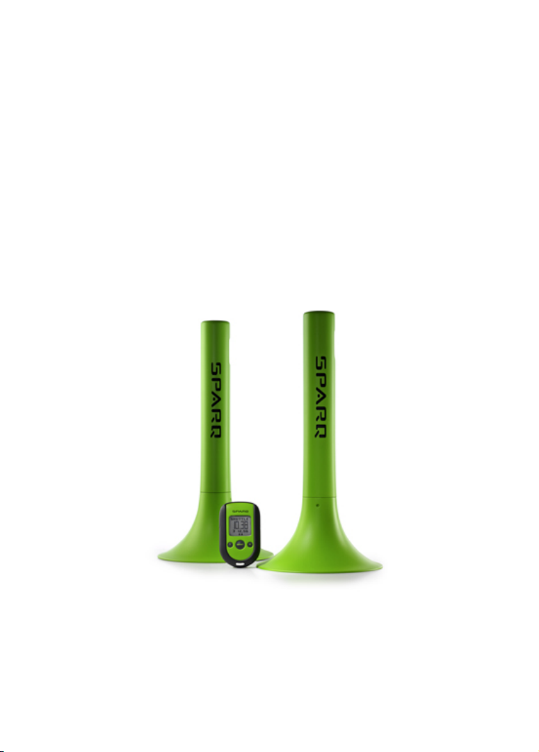
The SPARQ XLR8 Digital Timing System is a system for automatically
timing speed and agility drills. SPARQ Digital Cones generate directional
infrared beams and automatically start or stop the timing of a drill when
a beam is crossed. A SPARQ Handheld Controller controls the system.
The basic system includes a SPARQ Handheld Controller and two
SPARQ Digital Cones. This configuration provides enough power and
flexibility to run a wide variety of drills. Additional SPARQ Digital Cones
can be added to the system to give you the option of running more sophisticated drills and of timing more than one athlete at once.
7

8 CHAPTER 1. INTRODUCTION
1.2 Getting Started
1.2.1 Battery Installation
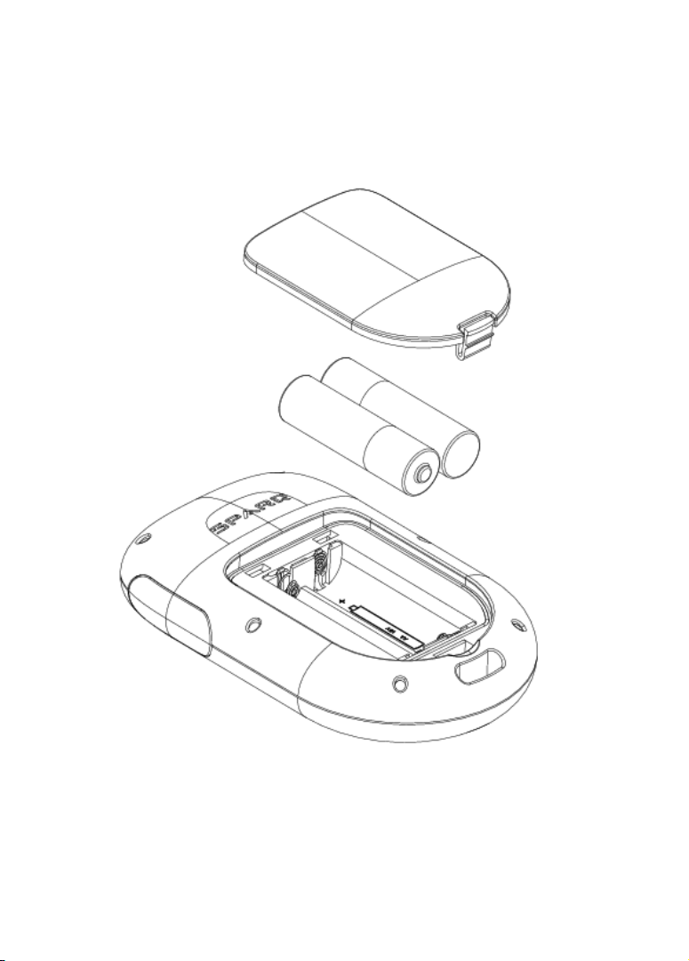
The Handheld Controller uses two size AA batteries. To install the batteries, lift the tab at the base of the battery compartment door on the back
of the Handheld Controller. Insert the batteries as shown in Figure 1.1.
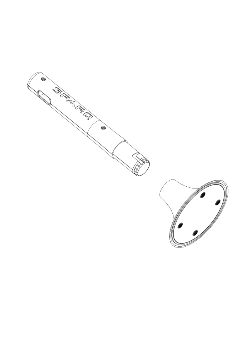
Each Digital Cone uses two size D batteries. To install the batteries, first
make a quarter-turn rotation of the cylinder, and remove the base as
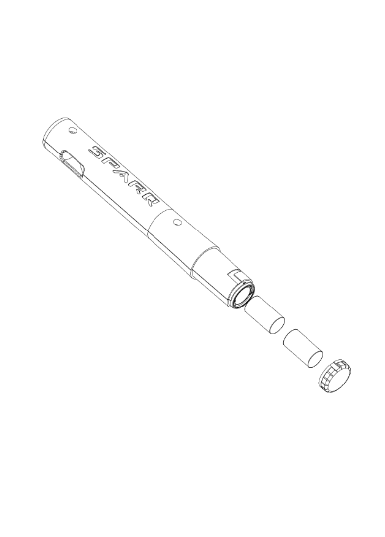
shown in Figure 1.2. Unscrew the cap at the base of the cylinder, and
insert the batteries as shown in Figure 1.3.
1.2. GETTING STARTED 9
Figure 1.1: Installing batteries in the SPARQ Handheld Controller
10 CHAPTER 1. INTRODUCTION
Figure 1.2: Removing the base of the Digital Cone
1.2. GETTING STARTED 11
Figure 1.3: Installing batteries in the SPARQ Digital Cone
12 CHAPTER 1. INTRODUCTION
1.2.2 Initial System Setup
The SPARQ XLR8 Digital Timing System requires that the Handheld
Controller be able to identify and communicate with the Digital Cones
that are to be used in the drills. The first time you use the system, follow
these steps to link the Handheld Controller and the Digital Cones.
1. Press the button at the top of each Digital Cone to power on the
Digital Cones. The LED at the top of each Digital Cone should
flash slowly, indicating that the Digital Cone is ready to link with the
Handheld Controller.
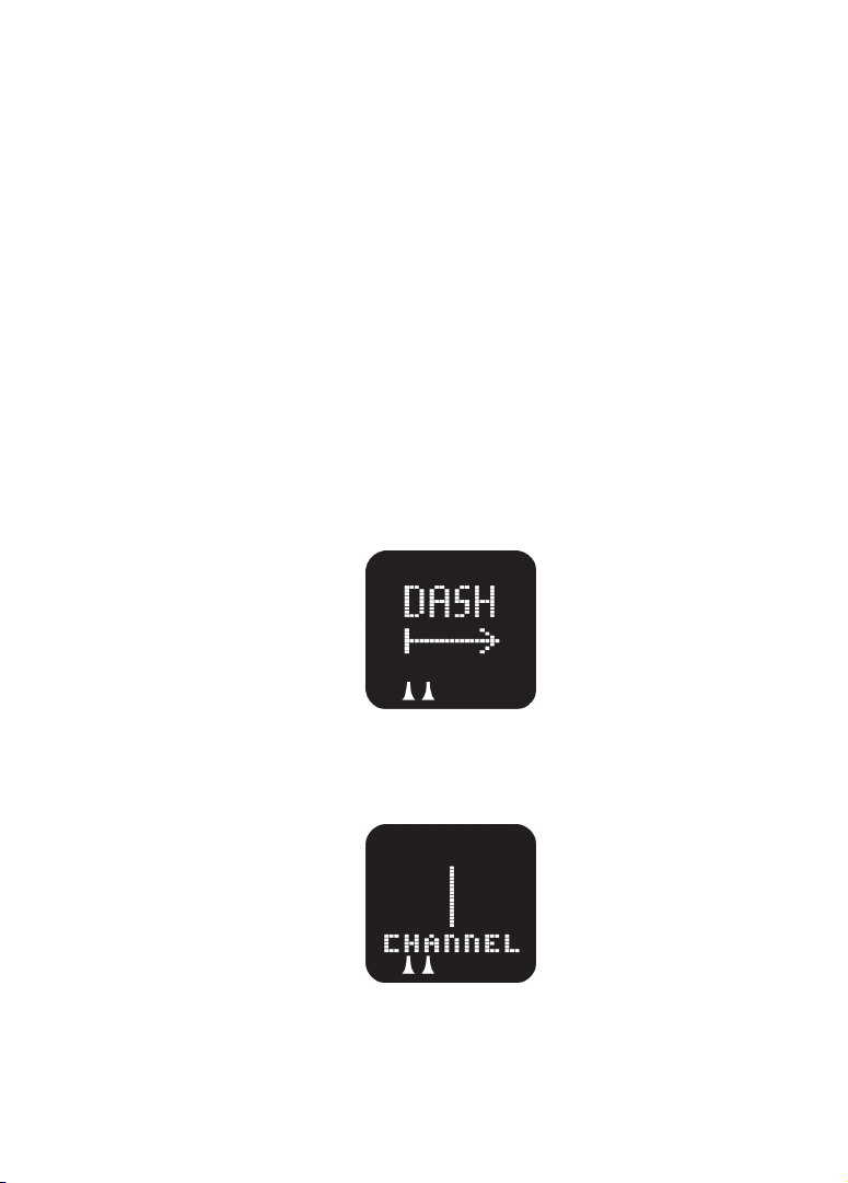
2. Press the button centered below the Handheld Controller display
to power on the Handheld Controller. The Handheld Controller display should briefly show a DRILL splash screen, then show DASH:
3. Press the button on the upper left side of the Handheld Controller
until Channel 1 is displayed:
If other Handheld Controllers are in use nearby, use the lower-left
and lower-right buttons to select an unused channel.
 Loading...