

SPARLING MainLine FM-104, MainLine FT-194-II, MainLine FM-181 Installation, Operaton & Maintenance Manual

TM
Issue Date: January 2006
FM104/FM184/FT194-II

NOTE:
To insure all warranties expressed or implied are allowed, it is important
that the unit be installed and calibrated per this manual. Follow all instructions starting in SECTION 1.0 on page 1 concerning verifying equipment and
operation, installation instructions, notes and wiring instructions.
SPARLING INSTRUMENTS, INC.
4097 N. Temple City Blvd.
El Monte, CA 91731
Ph (626) 444-0571
Fx (626) 452-0723
Email: sales@sparlinginstruments.com
Copyright© 2005 Sparling Instruments, Inc.
Website: sparlinginstruments.com
All rights reserved.

T ABLE OF
CONTENTS
Section 1 - Unpacking & Inspection .............1
1.1 Receiving & Inspection ..................................1
1.2 Storage ........................................................... 1
1.3 Operation ....................................................... 1
1.4 Specifications ................................................. 2
Section 2 - Pre-Installation............................3
2.1 Process Fluid ............................................... 3
2.2 Handling Precautions...................................3
Section 3 - Installation.....................................3
3.1 Site Selection Criteria ................................... 3
3.2 Mounting Tubes/Saddles .............................4
3.3 Mounting the Meterhead .............................. 5
Section 4 - Flow Rates & Dimensions ........ 6
Section 5 - Preventative Maintenance
of Meterhead .......................................................8
5.1 Annual Inspection of Meterhead .................... 8
5.2 Disassembly & Repair ................................... 9
5.3 Reassembly .................................................. 9
PagePage
Figures
1.1 Meter Operation ........................................... 1
3.1 Installation Considerations ...........................3
3.2 Tube mounting ............................................. 4
3.3 Tube mounting .............................................. 4
3.4 Tube mounting .............................................. 4
3.5 Install Straightening Vanes ............................. 4
4.1 Dimensions ................................................... 6
5.1 Inspection Steps ........................................... 8
5.2 Disassembly & Repair ................................... 9
7.1 Wiring Diagram............................................ 11
7.2 Forward/Reverse ........................................ 12
8.1 Programmer ............................................... 13
8.2 Connecting Programmer............................. 13
8.3 Password Menu .......................................... 13
8.4 Rate Menu ................................................... 15
8.5 Output Menu ............................................... 16
Tables
1. Flow & Dimensions ....................................... 7
2. Standard Registration for FT194-II............... 16
Section 6 - Preventative Maintenance ......10
6.1 Preventative Maintenance ............................ 10
6.2 Extended Battery Life ................................... 10
6.3 Troubleshooting .......................................... 10
Section 7 - Wiring Diagrams
Integral/Remote/4-20mA Output/
FT1 94 Forw ar d & Rev erse Register 11
Section 8 - Programming of
Electronic Totalizer.......................................... 13
8.1 Connecting the 705 Programmer ................ 13
8.2 Programming Mode.................................... 13
Section 9 - Replacement Parts List .............17
IDS104/184/194 Page i


1. 1 Receiving & Inspection
1.0
Unpacking &
Inspection
Locate the packing slip shipped with your unit, this will list all the items sent with the shipment.
Compare packing slip to order acknowledgement you received previously and verify that all items
correspond.
If all items correspond, examine the shipping containers for unusual denting and/or damage. If
shipping containers are in good condition, begin unpacking. Do a general examination of each
part as it is removed from its packaging, checking for any obvious signs of physical damage.
If there is no apparent damage to the items you may begin the installation procedure in SECTION 3,
although we recommend that you familiarize yourself with S
Considerations prior to going to S
If any item shows damage due to shipment call the Customer Service Department immediately, at
(626) 444-0571 you will then be advised of the measures to take.
If you find items are missing from your shipment, contact the Sparling Customer Service Department immediately, at (626) 444-0571. They will verify the order and trace any missing item for you.
ECTION 3.
ECTION 2: Application/Installation
1.2 Storage
This equipment should be stored in a clean, dry environment. Do not store outside in an
unprotected area. Observe the storage temperature requirements.
1.3
Operation
The Model's FM104 and FM184 feature the FT194-II battery powered electronic rate/totalizer which senses the rotation of the propeller by means of a magnetic pickup sensor located in the gearbox. The rate/totalizer and pickup are completely isolated from the
flow stream.
Utilizing the simple principle of the screw propeller, the Sparling
FM104/FM184 registers total flow, much as an odometer registers
auto mileage. The electronic rate/totalizer converts the revolutions
of the propeller to cubic feet, gallons or other standard engineering
volumetric units. The rotation of the propeller also affords a basis
for indicating and recording gallons per minute or other rates.
The LCD digital display is activated by a photoelectric cell. When
the cover of the bonnet is opened, the display is activated.
The display will go into "sleep mode" after a preprogrammed
time interval. Low light conditions may require the use of a
flashlight to activate and read the display.
Figure 1.1
Meter Operation
IDS-104/184/194 Page 1

1.4
Specifications
FM 104/184
Operating
Temperature 32°F to 100°F (higher temperature construction is available).
Storage Temperature -40°F to 175°F
Materials of
Construction Coverplate ..............................................................................Cast Iron (2" - 14")
Coverplate ..................................................................................Steel (16" - 72")
Propeller ......................................................................................... Polyethylene
Gearbox ................................................................................... Bronze (2" - 30")
Gearbox ............................................................................... Cast Iron (36" - 72")
Mechanical Parts........................................................................... Stainless Steel
Saddles ................................................................................ Cast Steel (6" - 14")
Saddles ..................................................................... Fabricated Steel (16" - 72")
Meter Tubes / Coatings ........ Cast Iron / stainless steel metering section (2" - 3")
Fabricated Steel (4" - 36")
Wetted parts high build epoxy polyamide paint EPA approved for potable water
FT 194-II
Accuracy Rate: ±0.25% of full scale
Totalization: ±0.1% of rate (in addition to propeller meter accuracy)
Power 3.6V Lithium battery (3 year average life)
4-20mA and scaled pulse output with external 24 Vdc power source
Battery operating temperature: -55°F to 185°F
Operating Temperature -10°F to 158°F (-23°C to 70°C)
Storage Temperature -40°F to 158°F (-40°C to 70°C)
Display 5-digit rate indicator (0.35 inches high)
8-digit totalizer indicator (0.25 inches high)
LCD display with simultaneous rate and total, and low battery indication.
Construction Sturdy die cast aluminum bonnet
NEMA-4X, NEMA-6, & IP67 environmental ratings.
Optional Outputs 4-20mA, scaled pulse output (open collector output, 100mA at 30 Vdc).
User selectable units of measure for every contact closure.
Power Supply vs. Output Load
Scaling Totalizer Scaler: .001 to 999999
Scaling Units Totalizer - Gallons, cubic feet, liters, cubic meters, acre feet
Electrical Rating General Purpose
Page 2 MainLine
Rate - GPM, CFS, MGD, LPS, M
3
/Hr
TM

2.0
PreInstallation
2.1 Process Fluid
The FM104 and FM184 MainLine Electronic Propeller Meters are designed to operate with relatively clean
process water. The percentage of solids should not exceed 0.5%. While the propeller shape is designed to shed
debris and the propeller material is durable and somewhat pliable, large solid objects in the flowing stream
could damage or become entangled in the propeller, causing inaccuracy or malfunction. These meterheads will
function despite the presence of small abrasive particles (such as sand) but the life of the propeller shaft
bearings may be reduced.
2.2 Handling Pr ecautions
Although this device is ruggedly constructed, it is a precise measuring instrument and can be damaged
by rough handling or if dropped. If the meterhead is not shipped already installed into a flow tube, care
should be taken to avoid damaging the propeller during installation.
3.1 Site Selection Criteria
3.0
Installation
Choose a location that
assures a full pipe of water
flowing at or above the
minimum velocity for the
meter. There should not be
any enlargements, diffusers
or obstructions upstream
that would produce a jet or
spiraling flow into the meter.
Ten diameters of straight
pipe upstream and 1
diameter downstream are
recommended to avoid
errors caused by skewed
velocity profiles. See figure
3.1.
A jet caused by a partially
opened valve, a centrifugal
pump, or a pipe enlargement upstream from the
meter can cause inaccurate registration.
Often such disturbances
can be avoided by locating
the meter on the suction
side of the pump. The
meter will register just as
efficiently on a vertical or
slanting pipe as on a
horizontal line. The straightening vanes eliminate cork-screw effects in the flow profile of water. Flow conditioners may be required in
installations where less than optimum conditions exist. See Figure 3.1.
Installation Considerations
Figure 3.1
IDS 104/184/194 Page 3
3. 2 Mounting Tubes & Saddles
3.0
Installation
cont'd.
Meterheads can be mounted into a round process line using 1)
a Sparling Model MT1 In-Line Flow Tube or 2) a Sparling Model
MS1 Welding Saddle.
3.2.1 Meterhead with MT1 In-Line Flow Tube (2" - 36")
a. Be sure to read Section 3.1 Site Selection Criteria
prior to installing your meter.
b. Install the meter tube in the line just as though it were
a short length of pipe.
c. The propeller must face the on-coming flow. Arrows
on the meter tube and cover plate will point in the
direction of the flow.
3.2.2 Meterhead with MS1 Welding Saddle (6" - 72")
a. For welding 6"-14" saddles to steel or wrought-iron
pipe, place the saddle on the pipe and scribe a
line INSIDE the saddle.
b. Cut or burn a full opening in the pipe so there will be
no projections of the pipe beyond the straight inside
edge of the saddle. Smooth the pipe around the
opening to make a good surface for the saddle.
c. Cast steel saddles (sizes 6" - 14") should be tacked
first, then welded in place, taking care not to overheat any part of the saddle.
Figure 3.2
Figure 3.3
Figure 3.4
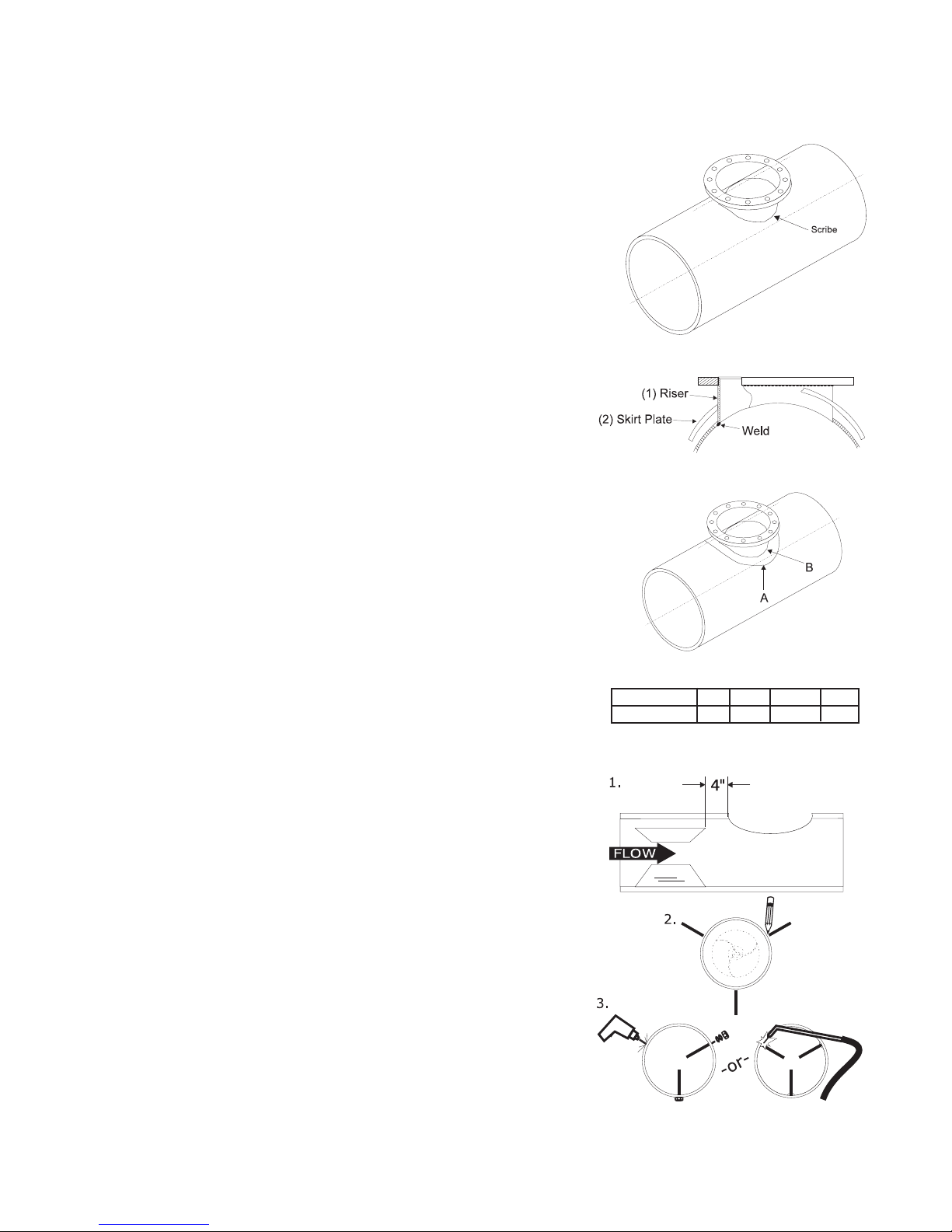
d. Fabricated steel saddles (sizes 16" - 72"):
(i) Place riser on pipe (Fig. 3.2). Scribe around
outside of riser as shown. Cut hole.
(ii) Insert riser into the hole in skirt plate (Fig. 3.3), do
not weld at this point. Pull skirt plate up against
the flange of riser.
(iii)Insert riser into cut-out in pipe. Make sure
bottom edge of riser is flush with I.D. of the
pipe and holes in the flange are straddling the
center line of pipe. Weld riser to inside pipe as
shown.
(iv)Lower skirt plate down onto pipe. Position to
achieve conformity with O.D. of pipe. Weld in a
continuous bead at point "A" and "B".
e. If straightening vanes are required, go
to section 3.2.3. If not, skip to section 3.3
3.2.3 Install straightening vanes (if required)
as shown on Figure 3.5.
Three straightening vanes are required.
Vanes should be equally spaced radially and
parallel with the longitudinal axis of the pipe (1)
Size Meter 6-14 16-30 36 & 42 48-72
Dimension "A" 4 8 12 15
a. b.
Figure 3.5
Install Straightening Vanes
Page 4 MainLine
TM
 Loading...