

SPARLING MainLine FM-104, MainLine FT-194-II, MainLine FM-181 Installation, Operaton & Maintenance Manual
Page 1

TM
Issue Date: January 2006
FM104/FM184/FT194-II
Page 2

NOTE:
To insure all warranties expressed or implied are allowed, it is important
that the unit be installed and calibrated per this manual. Follow all instructions starting in SECTION 1.0 on page 1 concerning verifying equipment and
operation, installation instructions, notes and wiring instructions.
SPARLING INSTRUMENTS, INC.
4097 N. Temple City Blvd.
El Monte, CA 91731
Ph (626) 444-0571
Fx (626) 452-0723
Email: [email protected]
Copyright© 2005 Sparling Instruments, Inc.
Website: sparlinginstruments.com
All rights reserved.
Page 3

T ABLE OF
CONTENTS
Section 1 - Unpacking & Inspection .............1
1.1 Receiving & Inspection ..................................1
1.2 Storage ........................................................... 1
1.3 Operation ....................................................... 1
1.4 Specifications ................................................. 2
Section 2 - Pre-Installation............................3
2.1 Process Fluid ............................................... 3
2.2 Handling Precautions...................................3
Section 3 - Installation.....................................3
3.1 Site Selection Criteria ................................... 3
3.2 Mounting Tubes/Saddles .............................4
3.3 Mounting the Meterhead .............................. 5
Section 4 - Flow Rates & Dimensions ........ 6
Section 5 - Preventative Maintenance
of Meterhead .......................................................8
5.1 Annual Inspection of Meterhead .................... 8
5.2 Disassembly & Repair ................................... 9
5.3 Reassembly .................................................. 9
PagePage
Figures
1.1 Meter Operation ........................................... 1
3.1 Installation Considerations ...........................3
3.2 Tube mounting ............................................. 4
3.3 Tube mounting .............................................. 4
3.4 Tube mounting .............................................. 4
3.5 Install Straightening Vanes ............................. 4
4.1 Dimensions ................................................... 6
5.1 Inspection Steps ........................................... 8
5.2 Disassembly & Repair ................................... 9
7.1 Wiring Diagram............................................ 11
7.2 Forward/Reverse ........................................ 12
8.1 Programmer ............................................... 13
8.2 Connecting Programmer............................. 13
8.3 Password Menu .......................................... 13
8.4 Rate Menu ................................................... 15
8.5 Output Menu ............................................... 16
Tables
1. Flow & Dimensions ....................................... 7
2. Standard Registration for FT194-II............... 16
Section 6 - Preventative Maintenance ......10
6.1 Preventative Maintenance ............................ 10
6.2 Extended Battery Life ................................... 10
6.3 Troubleshooting .......................................... 10
Section 7 - Wiring Diagrams
Integral/Remote/4-20mA Output/
FT1 94 Forw ar d & Rev erse Register 11
Section 8 - Programming of
Electronic Totalizer.......................................... 13
8.1 Connecting the 705 Programmer ................ 13
8.2 Programming Mode.................................... 13
Section 9 - Replacement Parts List .............17
IDS104/184/194 Page i
Page 4

Page 5

1. 1 Receiving & Inspection
1.0
Unpacking &
Inspection
Locate the packing slip shipped with your unit, this will list all the items sent with the shipment.
Compare packing slip to order acknowledgement you received previously and verify that all items
correspond.
If all items correspond, examine the shipping containers for unusual denting and/or damage. If
shipping containers are in good condition, begin unpacking. Do a general examination of each
part as it is removed from its packaging, checking for any obvious signs of physical damage.
If there is no apparent damage to the items you may begin the installation procedure in SECTION 3,
although we recommend that you familiarize yourself with S
Considerations prior to going to S
If any item shows damage due to shipment call the Customer Service Department immediately, at
(626) 444-0571 you will then be advised of the measures to take.
If you find items are missing from your shipment, contact the Sparling Customer Service Department immediately, at (626) 444-0571. They will verify the order and trace any missing item for you.
ECTION 3.
ECTION 2: Application/Installation
1.2 Storage
This equipment should be stored in a clean, dry environment. Do not store outside in an
unprotected area. Observe the storage temperature requirements.
1.3
Operation
The Model's FM104 and FM184 feature the FT194-II battery powered electronic rate/totalizer which senses the rotation of the propeller by means of a magnetic pickup sensor located in the gearbox. The rate/totalizer and pickup are completely isolated from the
flow stream.
Utilizing the simple principle of the screw propeller, the Sparling
FM104/FM184 registers total flow, much as an odometer registers
auto mileage. The electronic rate/totalizer converts the revolutions
of the propeller to cubic feet, gallons or other standard engineering
volumetric units. The rotation of the propeller also affords a basis
for indicating and recording gallons per minute or other rates.
The LCD digital display is activated by a photoelectric cell. When
the cover of the bonnet is opened, the display is activated.
The display will go into "sleep mode" after a preprogrammed
time interval. Low light conditions may require the use of a
flashlight to activate and read the display.
Figure 1.1
Meter Operation
IDS-104/184/194 Page 1
Page 6
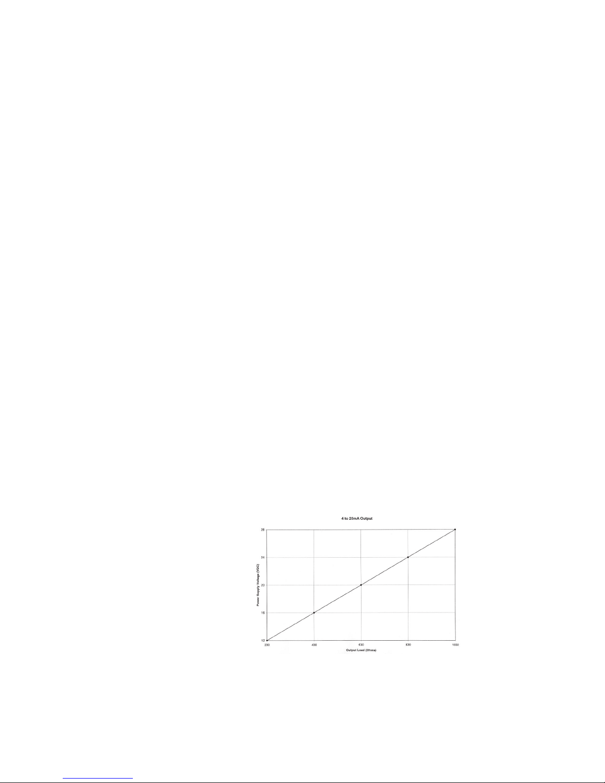
1.4
Specifications
FM 104/184
Operating
Temperature 32°F to 100°F (higher temperature construction is available).
Storage Temperature -40°F to 175°F
Materials of
Construction Coverplate ..............................................................................Cast Iron (2" - 14")
Coverplate ..................................................................................Steel (16" - 72")
Propeller ......................................................................................... Polyethylene
Gearbox ................................................................................... Bronze (2" - 30")
Gearbox ............................................................................... Cast Iron (36" - 72")
Mechanical Parts........................................................................... Stainless Steel
Saddles ................................................................................ Cast Steel (6" - 14")
Saddles ..................................................................... Fabricated Steel (16" - 72")
Meter Tubes / Coatings ........ Cast Iron / stainless steel metering section (2" - 3")
Fabricated Steel (4" - 36")
Wetted parts high build epoxy polyamide paint EPA approved for potable water
FT 194-II
Accuracy Rate: ±0.25% of full scale
Totalization: ±0.1% of rate (in addition to propeller meter accuracy)
Power 3.6V Lithium battery (3 year average life)
4-20mA and scaled pulse output with external 24 Vdc power source
Battery operating temperature: -55°F to 185°F
Operating Temperature -10°F to 158°F (-23°C to 70°C)
Storage Temperature -40°F to 158°F (-40°C to 70°C)
Display 5-digit rate indicator (0.35 inches high)
8-digit totalizer indicator (0.25 inches high)
LCD display with simultaneous rate and total, and low battery indication.
Construction Sturdy die cast aluminum bonnet
NEMA-4X, NEMA-6, & IP67 environmental ratings.
Optional Outputs 4-20mA, scaled pulse output (open collector output, 100mA at 30 Vdc).
User selectable units of measure for every contact closure.
Power Supply vs. Output Load
Scaling Totalizer Scaler: .001 to 999999
Scaling Units Totalizer - Gallons, cubic feet, liters, cubic meters, acre feet
Electrical Rating General Purpose
Page 2 MainLine
Rate - GPM, CFS, MGD, LPS, M
3
/Hr
TM
Page 7

2.0
PreInstallation
2.1 Process Fluid
The FM104 and FM184 MainLine Electronic Propeller Meters are designed to operate with relatively clean
process water. The percentage of solids should not exceed 0.5%. While the propeller shape is designed to shed
debris and the propeller material is durable and somewhat pliable, large solid objects in the flowing stream
could damage or become entangled in the propeller, causing inaccuracy or malfunction. These meterheads will
function despite the presence of small abrasive particles (such as sand) but the life of the propeller shaft
bearings may be reduced.
2.2 Handling Pr ecautions
Although this device is ruggedly constructed, it is a precise measuring instrument and can be damaged
by rough handling or if dropped. If the meterhead is not shipped already installed into a flow tube, care
should be taken to avoid damaging the propeller during installation.
3.1 Site Selection Criteria
3.0
Installation
Choose a location that
assures a full pipe of water
flowing at or above the
minimum velocity for the
meter. There should not be
any enlargements, diffusers
or obstructions upstream
that would produce a jet or
spiraling flow into the meter.
Ten diameters of straight
pipe upstream and 1
diameter downstream are
recommended to avoid
errors caused by skewed
velocity profiles. See figure
3.1.
A jet caused by a partially
opened valve, a centrifugal
pump, or a pipe enlargement upstream from the
meter can cause inaccurate registration.
Often such disturbances
can be avoided by locating
the meter on the suction
side of the pump. The
meter will register just as
efficiently on a vertical or
slanting pipe as on a
horizontal line. The straightening vanes eliminate cork-screw effects in the flow profile of water. Flow conditioners may be required in
installations where less than optimum conditions exist. See Figure 3.1.
Installation Considerations
Figure 3.1
IDS 104/184/194 Page 3
Page 8
3. 2 Mounting Tubes & Saddles
3.0
Installation
cont'd.
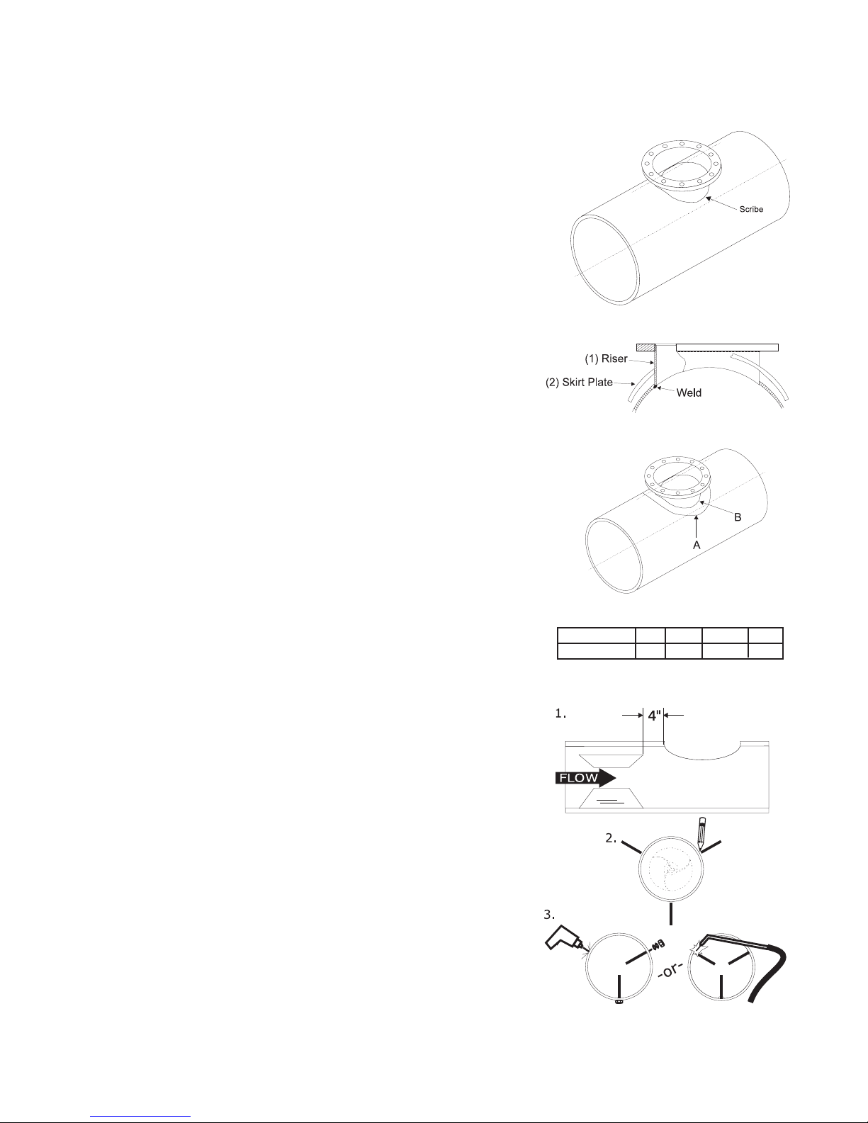
Meterheads can be mounted into a round process line using 1)
a Sparling Model MT1 In-Line Flow Tube or 2) a Sparling Model
MS1 Welding Saddle.
3.2.1 Meterhead with MT1 In-Line Flow Tube (2" - 36")
a. Be sure to read Section 3.1 Site Selection Criteria
prior to installing your meter.
b. Install the meter tube in the line just as though it were
a short length of pipe.
c. The propeller must face the on-coming flow. Arrows
on the meter tube and cover plate will point in the
direction of the flow.
3.2.2 Meterhead with MS1 Welding Saddle (6" - 72")
a. For welding 6"-14" saddles to steel or wrought-iron
pipe, place the saddle on the pipe and scribe a
line INSIDE the saddle.
b. Cut or burn a full opening in the pipe so there will be
no projections of the pipe beyond the straight inside
edge of the saddle. Smooth the pipe around the
opening to make a good surface for the saddle.
c. Cast steel saddles (sizes 6" - 14") should be tacked
first, then welded in place, taking care not to overheat any part of the saddle.
Figure 3.2
Figure 3.3
Figure 3.4
d. Fabricated steel saddles (sizes 16" - 72"):
(i) Place riser on pipe (Fig. 3.2). Scribe around
outside of riser as shown. Cut hole.
(ii) Insert riser into the hole in skirt plate (Fig. 3.3), do
not weld at this point. Pull skirt plate up against
the flange of riser.
(iii)Insert riser into cut-out in pipe. Make sure
bottom edge of riser is flush with I.D. of the
pipe and holes in the flange are straddling the
center line of pipe. Weld riser to inside pipe as
shown.
(iv)Lower skirt plate down onto pipe. Position to
achieve conformity with O.D. of pipe. Weld in a
continuous bead at point "A" and "B".
e. If straightening vanes are required, go
to section 3.2.3. If not, skip to section 3.3
3.2.3 Install straightening vanes (if required)
as shown on Figure 3.5.
Three straightening vanes are required.
Vanes should be equally spaced radially and
parallel with the longitudinal axis of the pipe (1)
Size Meter 6-14 16-30 36 & 42 48-72
Dimension "A" 4 8 12 15
a. b.
Figure 3.5
Install Straightening Vanes
Page 4 MainLine
TM
Page 9

3.0
Installation
cont'd.
Bolting Vanes
a. For easy vane installation, place each vane in its equivalent position on the outside of the pipe (2) and
mark the location for bolt holes.
b. Drill holes. Install vanes inside the pipe. Place lead washer and then steel washer on the bolt on
outside of pipe and tighten nuts securely (3a).
Welding Vanes
a. Space vanes equally at 120° radially and loc ate longitudina ll y as shown.
b. (3b) Secure vanes with a continuous bead weld around both ends and with intermittant staggered
bead welds along the vane.
Note: Installations with both forward and reverse
flows* may require additional vanes on the
downstream side of the meter. Install in the same
manner, 4" from the downstream saddle opening.
*Option requiring dual remote mounted totalizers.
3. 3 Mounting the Meterhead
3.3.1 Tube mounted meters (2" - 36")
2"-4" - Not required - meterheads are shipped with meterhead mounted in place.
6" -36" - Follow direc tio ns per Section 3. 3.2 following.
3.3.2 Saddle meters (6" - 72")
a. Place gasket on the face of the saddle
b. 6" - 8" Met ers
Hold meterhead with propeller facing UPSTREAM.
Lower propeller into pipe and slide it upstream to position for capscrews and secure the
coverplate.
c. 10" - 72" Meters
Hold meterhead over opening with propeller toward you and blades lengthwise with the
pipe.
Tilt coverplate toward you.
Lower until one blade lies horizontally on the end of the saddle.
Ease the propeller down through the saddle with a "rolling" motion.
Turn the headplate so that the propeller faces upstream.
Th e arrow on the plate points in t he d irection of the flow. Tighten cap screws evenly (6"-14" sizes)
Insert screws and install nuts (16" - 72" only) tighten them evenly, and meter is ready to operate.
IDS 104/184/194 Page 5
Page 10

4.0
Flow Rates &
Dimensions
Maximum flow ranges can be safely exceeded by 50% when used intermittently (10-15% of the time). Your Sparling
meter utilizes specially designed propellers and bearings matched to your flow range to insure long life.
For proper configuration of meter construction anticipated flow ranges, including minimum and
normal flow rates expected, should always be specified on application sheets acocmpanying your
order.
Integral Mount
Remote Mount
3.781"
2.125"
.125"
Page 6 MainLine
2.995"
Figure 4.1
Dimensions
TM
Page 11

TABLE 1 - FLOW & DIMENSIONS
Weight (lbs) Dimensions (inches) Flow (gpm)
Fabr. Cast B M Low Flow Std. Flow
Size Steel Iron L W
2 20 8.13 5.13 2.38 4.00 3.13 0.50 1.75 1.75 2.56 30 - 80 60 - 150
3 20 8.25 6.25 2.75 4.00 3.18 0.63 2.75 2.75 2.56 35 - 200 70 - 360
4 20 9.50 6.75 3.50 6.94 4.13 0.63 3.44 3.44 2.56 50 - 400 120 - 600
6 25 10.38 7.31 4.75 6.31 3.69 0.94 4.25 4.25 2.93 90 - 900 200 - 1600
8 29 11.00 10.63 7.00 6.31 5.81 -0.32 5.31 5.31 2.81 100 - 1200 240 - 2300
10 34 11.00 10.63 8.00 6.31 5.81 -0.32 6.31 6.31 2.81 125 - 1600 320 - 3000
12 36 11.00 10.63 10.00 6.31 5.81 -0.32 7.31 7.31 2.81 150 - 2200 400 - 4000
14 37 11.00 10.63 11.00 6.31 5.81 -0.32 8.00 8.00 2.81 250 - 3000 520 - 5000
16 210 23.50 23.50 13.00 12.00 8.20 4.25 12.25 12.25 2.88 350 - 3800 700 - 6800
18 210 23.50 23.50 16.00 12.00 8.20 4.25 13.25 13.50 2.88 450 - 4500 900 - 8100
20 215 23.50 23.50 16.00 12.00 8.20 4.25 14.25 14.50 2.88 550 - 5500 1100 - 9900
24 215 23.50 23.50 16.00 12.00 8.20 4.25 16.25 16.50 2.88 800 - 8500 1600 - 15000
30 220 23.50 23.50 16.00 12.00 8.20 4.25 19.25 19.50 2.88 1200 - 12000 3000 - 21600
36 825 32.00 32.00 25.25 18.75 9.20 6.50 23.00 24.00 3.13 1500 - 16000 3000 - 28800
42 835 32.00 32.00 25.25 18.75 9.20 6.50 26.00 27.00 3.13 2000 - 22000 4200 - 40000
48 1350 38.75 38.75 25.25 18.75 9.50 9.50 29.50 30.50 3.25 2500 - 28000 5400 - 50000
54 1360 38.75 38.75 25.25 18.75 9.50 9.50 32.50 33.50 3.25 3200 - 35000 6800 - 63000
60 1370 38.75 38.75 25.25 18.75 9.50 9.50 35.50 36.50 3.25 4000 - 42000 8400 - 76000
66 1380 38.75 38.75 25.25 18.75 9.50 9.50 38.50 39.50 3.25 4750 - 50000 10000 - 90000
72 1390 38.75 38.75 25.25 18.75 9.50 9.50 41.00 42.50 3.25 5500 - 60000 12000 -110000
"B" 16" - 72" for 150 psi only
CE GH
150 lbs 250 lbs
N
Min. Max. Min. Max.
IDS 104/184/194 Page 7
Page 12
5.1 Preventative Maintenance — Annual Inspection of Meterhead
5.0
Meter
Maintenance
Preventative maintenance of the FM104 and FM184 is limited to annual inspection of the propeller shaft bearings, propeller, straightening vanes and tube condition.
5.1.1 Remove Meterhead
Depressurize the line, remove the cap screws and slide the meterhead in the downstream direction.
Lift the downstream end of the coverplate and withdraw the meter from the line. It may be necessary
to maneuver the meter so that one blade tip can be lifted through the opening, allowing clearance for
the remaining blades.
5.1.2 Inspect vanes for damage and tubes and vanes for foreign matter
Examine the pipe for any foreign matter that may have accumulated. Look at the upstream ends of
the straightening vanes and remove accumulated matter. See if the vanes have been damaged straighten any bends.
5.1.3 Inspect Propeller & Bearings
a. See that the propeller blades are smooth and clean.
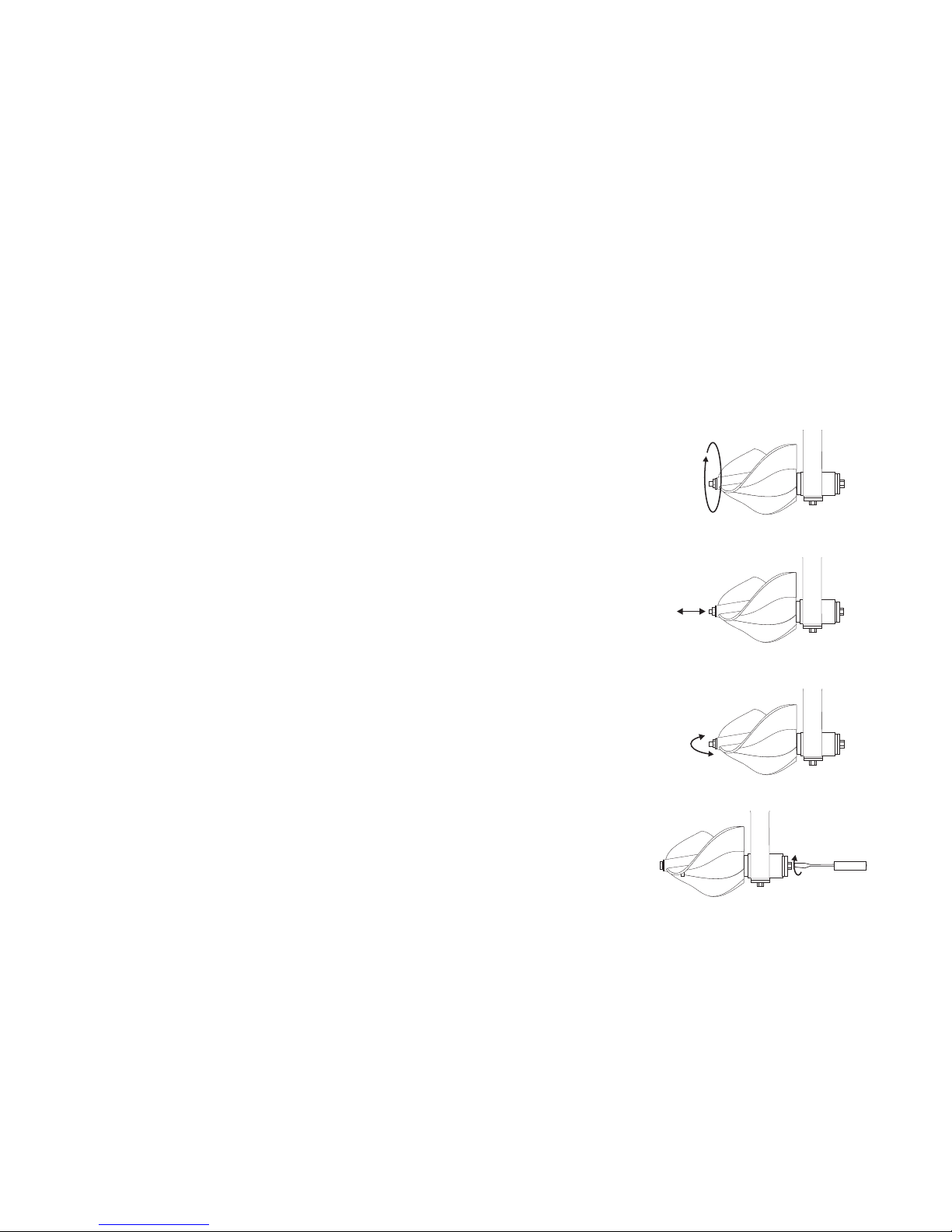
b. Spin the propeller with your fingers (a). The propeller
should spin freely without binding and crunching noises.
The register should advance properly.
c. Next, pull on the propeller (b). The propeller should
have a little freedom of movement (about 1/64") due to the
designed play in the bearings which allows grit to pass
through. If movement is over 1/64" but under 1/32" adjust
per 5.1.4 Adjust Bearings.
a.
b.
d. Finally, hold the propeller with your fingers and rock it
from side to side (c). There should be minimal movement
when rocking the propeller, about 1/64".
If you exp erience:
binding or crunching when spinning the propeller
the propeller has excessive play
it could signal excess bearing wear or failure. Go to Section
5.2 Disassembly and Repair
If the register does not advance properly, go to Section 5.2
Disassembly and Repair.
Check the gasket before replacing the meterhead. Replace it
if it is damaged. Finally, if everything checks out as it should,
return meter to line, bolt in place and repressurize the line.
5.1.4 Adjust Bearings
The front propeller shaft bearing is the key to the life of the meter. If it is kept in good condition the
other parts will last almost indefinitely.
Adjust the thrust screw (d) on the back of the propeller shaft plug to achieve 1/64" end play.
Screw the thrust screw until it comes in contact with the end of the propeller shaft, then back off
the thrust screw 1/4 turn and tighten the locknut and re-check the end play.
Spin the propeller to ensure that it spins freely and that the register advances properly. No further
maintenance is required and the meter may be reinstalled. If you found a problem, proceed to 5.2
Disassembly & Repair.
c.
d.
Figure 5.1
Inspection Steps
Page 8 MainLine
TM
Page 13
5.2 Disassembly & Repair
5.0
Meter
Maintenance
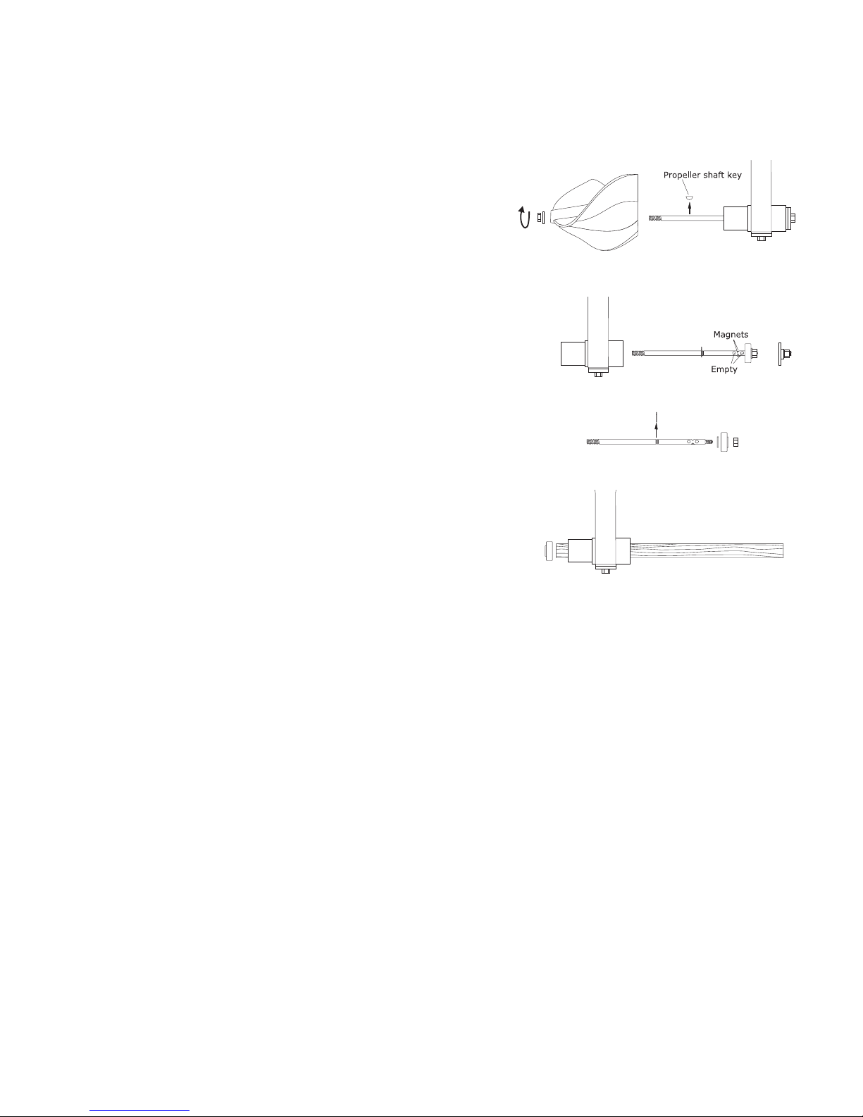
5.2.1 Grip the propeller and remove the propeller
nut. Slip the propeller off by tapping it lightly
and remove the propeller shaft key (a).
5.2.2 Remove the propeller shaft plug assembly and
drive the propeller shaft out the rear of the gear
box by tapping at the end of the propeller shaft
with a rubber mallet or a piece of wood to protect the shaft (b). While removing you may have
to rotate the shaft to avoid damaging the bearing retaining ring - do not force.
5.2.3 G rip the propeller shaft be tw een the magnets and the front bearing retaining ring. Remove the rear bearing nut, rear bearing, rear
bearing washer and the front bearing retaining
ring (c). Inspect the propeller shaft for
straightness, carefully examining magnet discs
for cracks, looseness or missing discs. If faulty,
a new propeller shaft must be installed.
5.2.4 Using a wooden dowel, gently tap out the front
bearing from the gear box (d).
5.2.5 Check both bearings for wear and excessive
play. Replace worn out bearings.
5.3 Reassembly
a.
b.
c.
d.
Figure 5.2
Disassembly & Repair
5.3.1 Install the front bearing by pushing the bearing into the gearbox. DO NOT HAMMER THE BEARING
INTO PLACE. Coat bearing with Lubriplate.
5.3.2 Install the rear bearing washer, rear bearing and the bearing retainer nut on the propeller shaft. Tighten the
nut snugly, but do not over-tighten. Coat bearing with Lubriplate.
5.3.3 Install the front bearing retainer on the propeller shaft. The retainer should be placed in the front slot for
ball bearings or in the rear slot for rubber bearings. Note: there is a rou nde d side and a sh arp side to the
front bearing retaining ring. Be sure to put t he r ounded side to wa rd t he propeller.
5.3.4 Insert the propeller shaft assembly into the rear of the gearbox. Rotate the shaft if necessary to avoid
damaging the front bearing retaining ring. Reinstall the propeller shaft thrust plug assembly and tighten
firmly.
5.3.5 Install the propeller shaft key, the propeller, and the propeller washer and nut. Use the new propeller nut
furnished with the front bearing. Tighten the nut snugly.
5.3.6 Check the propeller shaft end play. Adjust the thrust screw on the back of the propeller shaft plug to
achieve 1/64" end play. Screw the thrust screw until it comes in contact with the end of the propeller shaft,
back of thrust screw 1/4 turn and tighten the lock nut and recheck the end play.
5.3.7 Spin the propeller and check for free movememt and that the register advances properly. Binding
bearings may be freed by alternate light taps to the rear of the gearbox and the front of the propeller shaft
to properly seat the bearings. Recheck propeller shaft end play.
IDS 104/184/194 Page 9
Page 14

6.1 Preventative Maintenance
6.0
Maintenance
The ideal time to inspect the unit is when you are changing the battery.
6.1.1 Inspect battery contacts
Examine the battery contacts for signs of moisture intrusion. Examine the battery for any signs
of leakage.
6.1.2 Inspect Connectors
There are two connectors. One on each side of the battery bracket. Check each for moisture
intrusion.
6. 2 Preventative Maintenance – Extended Battery Life
To extend battery life please do the following
6.2.1 Remove battery during storage or after disconnecting power to prolong life.
6.2.2 In low light conditions shine flashlight on display to activate.
6.2.3 Always close lid.
6.3 Troubleshooting
6.3.1 Rate and Totalizer do not indicate
Bad contact? Examine & clean.
Propeller Jammed? See Section 5.2 Disassembly & Repair
Damaged or missing magnets in propeller shaft? See Section 5.2 Disassembly & Repair
6.3.2 Contacts corroded
Moisture intrusion? Totalizer was not replaced properly. Replace totalizer.
Page 10 MainLine
TM
Page 15

7.0
Wiring Diagram
See Page 12
IDS 104/184/194 Page 11
Figure 7.1
Page 16

7.0
Wiring
Diagram
FT194-II
Forward &
Reverse
Register
Page 12 MainLine
Figure 7.2
4-20mA Installation on Forward/Reverse Unit
TM
Page 17

8.0
Programming
A 705 Sparling programmer is required to access the programmable parameters for the unit.
Figure 8.1
8.1 Connecting the 705 Programmer:
Remove the mounting screws. Access the bottom of the unit and plug the programmer in the 5-pin connector
as shown.
8.2 Programming Mode:
8.2.1 General Guide when using the menu:
a. Moving the cursor past the farthest digit to the right will enter the value.
b. Moving the decimal point: remove the current point first by making it a zero, then place the new
point where desired.
c. Once in a sub-menu (Rate, Total, Display, etc) you must go through to get back to the main
menu.
8.2.2 Entering menu:
a. Press the left or right arrow key on the 705 programmer to access the main menu. The screen
will change to that of figure 8.3. Use the right/left keys to move the cursor to the next/previous
digit and up/down to scroll the digit. Press the right key when the cursor is under the farthest
digit to the right to enter the value.
Figure 8.2
IDS 104/184/194 Page 13
Figure 8.3
Page 18

8.0
Programming
cont'd.
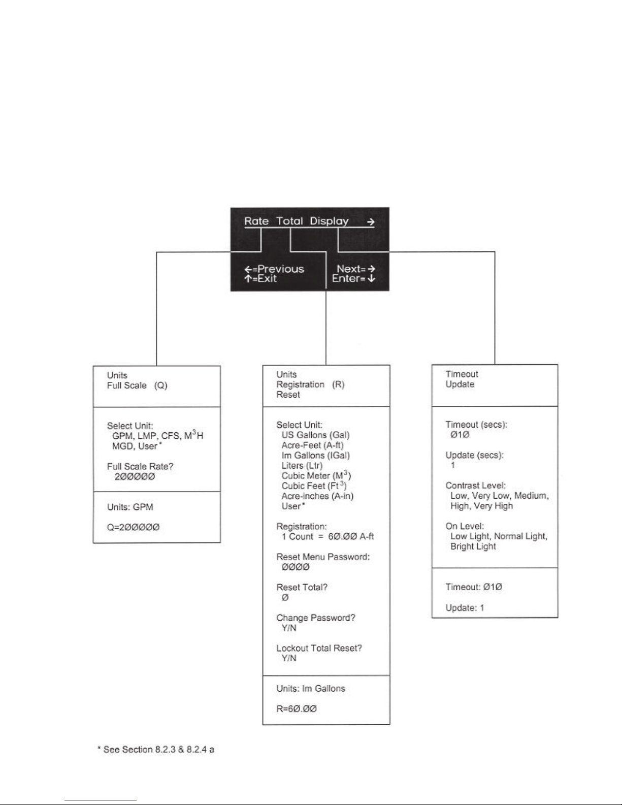
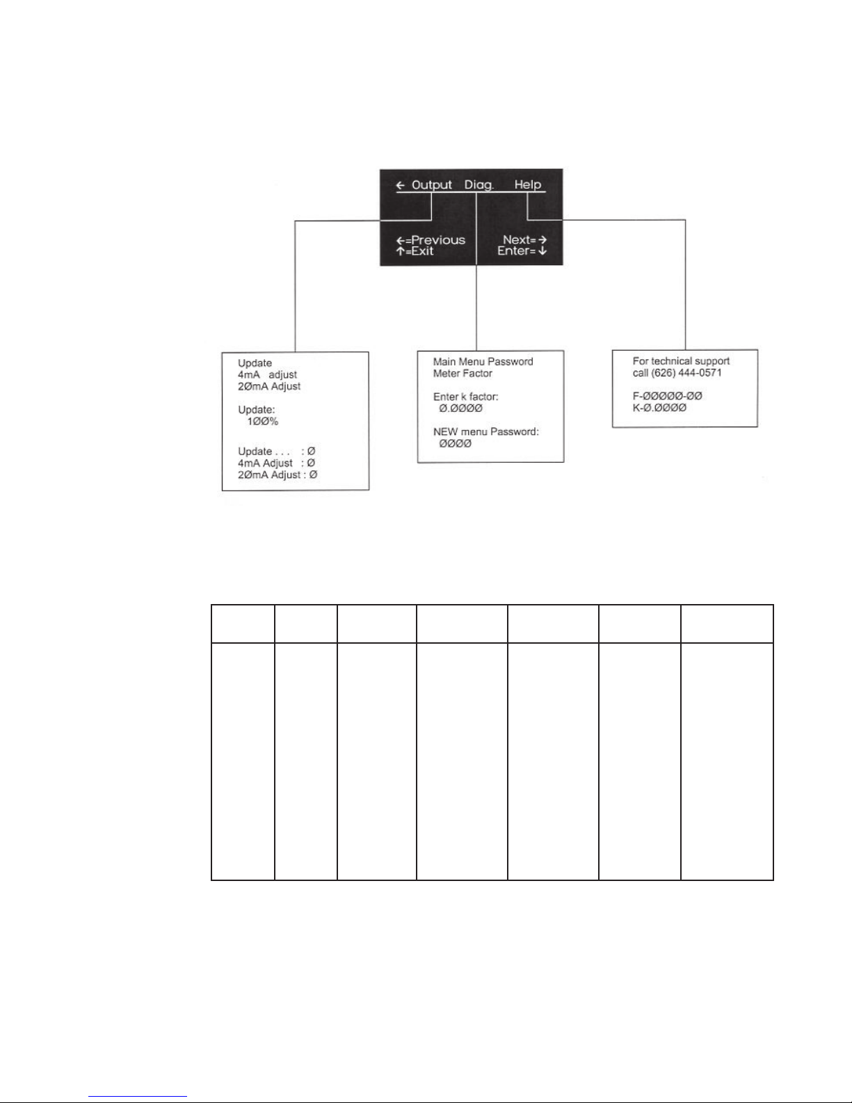
b. There are two screens for the main menu. The first one (figure 8.4) allows access to Rate, Total
and display parameters. The second one (figure 8.5) has Output, Diagnostics (Diag.) and Help.
Press the right arrow when Display is highlighted to access the second screen. Move left one
more time when Output is highlighted on the second screen to get back to the first.
8.2.3 Main Menu Rate
a. The Rate menu allows access to Units and Full scale. Predefined units are: GPM, LPM, CFS,
M3H, MGD. If none of the predefined units match your application, set the units to User. This
allows you to define the unit name and conversion factor.
b. Full Scale affects the 4-20mA loop current only. At full scale of the rate, the loop current will be
20mA. A zero flow will make it 4mA.
8.2.4 Main Menu Total (Totalizer)
a. The Total menu allows access to Units, Registration and the Totalizer Reset menu. Predefined
units are: US Gallons (Gal), Acre-Feet (A-ft), Imperial Gallons (IGal), Liters (Ltr),
Cubic meters (M3), Cubic feet (Ft3), Acre-inches (A-in). If none of the predefined
units match your application, set the units to User. This allows you to define the unit name and
conversion factor.
b. The registration value is used to divide the internal (and external) totalizer by the required
number of engineering units. It is normally set to an even number like 0.1, 1, 10, etc. Example:
If set to 10, the internal totalizer will increment by one count every 10 units (where units can be
any totalizer specified unit). At the same time, a pulse will be driven to the external pulse output.
Reset sub-menu: This sub section of the Totalizer menu (if available) let the user Reset,
lockout or change the password for the totalizer.
Reset: Makes the value of the totalizer zero.
Change password: Changes the password for this sub-menu
Lockout: It disables this sub-menu. Warning: lockout is final!
8.2.5 Main Menu Display
The Display menu allows access to Timeout, Update, Contrast and On level.
Timeout: Sets the number of seconds the display will stay on if the lid is not closed.
Update: The display rate and totalizer values will be updated according to this value.
Contrast: Sets how dark or light the display looks.
On level: Sets the brightness of the light required to turn on the display after the lid is open.
8.2.6 Main Menu Output
a. The Output menu allows access to Update, 4-20mA adjustment.
Update: Sets how much of the new flow value is used to update the outputs. Use a smaller value to slow
the tracking of the output to the display rate indicator.
b. 4-20mA calibration - The 4 and 20mA are calibrated at the factory. There should be no need for
re-calibration under normal operating conditions but due to tolerances in equipment, the user
may want to fine tune the output to its own equipment.
This section is only available if the unit is loop powered. The actual value have no direct
relevance to the output. It is only a visual indication of how much the output can be changed.
Each 4 and 20mA allow a range of ± 75 steps. The value is saved in non-volatile memory once
entered.
Page 14 MainLine
TM
Page 19
8.0
Programming
cont'd.
8.2.7 Main Menu Diag. (Diagnostics)
The Diagnostic menu allow the user to change the meter factor and the main menu password.
8.2.8 Main Menu Help
The Help menu shows the serial number, meter factor and technical support information.
IDS 104/184/194 Page 15
Figure 8.4
Figure 8.4
Page 20
8.0
Programming
cont'd.
Figure 8.5
TABLE 2 S TANDARD REGISTRATION FOR FT194-II
Nom. Cubic U.S. Imperial Acre Cubic
Size Feet Gallons Gallons Feet Meters Liters
2 1.0 10.0 10.0 0.00001 0.01 10.0
3 1.0 10.0 10.0 0.0001 0.1 100.0
4 10.0 100.0 100.0 0.0001 0.1 100.0
5 10.0 100.0 100.0 0.0001 0.1 100.0
6 10.0 100.0 100.0 0.001 1.0 100.0
8 10.0 100.0 100.0 0.001 1.0 1000.0
10 100.0 100.0 100.0 0.001 1.0 1000.0
12 100.0 1000.0 1000.0 0.001 1.0 1000.0
14 100.0 1000.0 1000.0 0.001 1.0 1000.0
16 - 30 100.0 1000.0 1000.0 0.01 10.0 10000.0
36 & 42 1000.0 10000.0 10000.0 0.01 10.0 10000.0
48 - 72 1000.0 10000.0 10000.0 0.1 100.0 100000.0
Page 16 MainLine
TM
Page 21
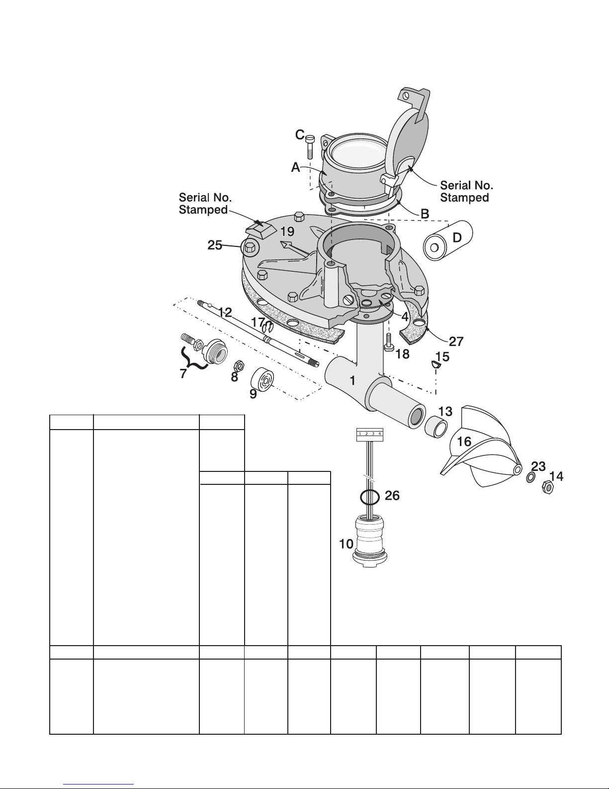
9.0
Replacement
Parts List
2" to 14"
Item No. Description P/N
A FT194 Totalizer* FT194
B Totalizer Gasket 521361
C Register Bolt 101238(2)
D Battery, D Cell 154946
2-14" 16-30" 36-72"
4 Gasket Gear Box/Drop Pipe 501876 559635 560260
8 Hex Nut 100313 100313 111972
7 Prop Shaft Plug Assy 504903 534562 538340
9 Rear Bearing 124529 523557 124602
10 Inductor Assy w/Plug 558249 559627 560351
12 Propeller Shaft 558950 559560 535601
13 *Front Bearing, Steel 129959 523549 528383
14 Nut 100321 112003 131095
15 Shaft Key 100355 100355 121989
17 Retainer Ring 100397 111344 121806
18 Bolt 100298(4) 109480(4) 108987(4)
23 Washer 100389 112805 517899
26 O-Ring 100454 100454 100454
Item No. Descr iption 2" 3" 4" 6" 8" 10" 12" 14"
1 Gear Box 503252 503278 503294 503335 503351 503377 503393 503418
16 Propeller* 502056 502064 502080 502098 502105 502113 502121 502139
19 Cover Plate* 501272 501298 501363 501389 501404 501404 501404 501404
25 Hex Hd Cap Screw 100272 (10) 100272 (10) 132374 (8) 100272 (10) 130336 (10) 130336 (10) 130336 (10) 103336 (10)
27 Cover Plate Gasket 504937 504945 504953 504961 504976 504976 504976 504976
Dummy Cover Plate 512334 512352 516966 512360 512378 512378 512378 512378
*Contact factory for high velocity applications. Front rubber bearings are required in lieu of steel.
IDS 104/184/194 Page 17
Page 22
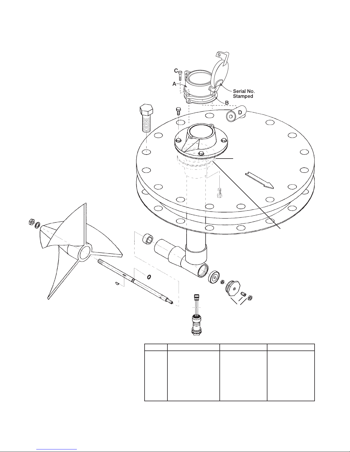
9.0
Replacement
Parts List
16" - 72"
25
28
19
14
23
16
15
27
13
4
1
9
17
8
12
7
Item No. Description 16" - 30" 36" - 72"
1 Gear Box Assy. 510976 519481
16 Propeller* * *
19 Cover Plate* 530520 539538
25 Hex Hd Cap Screw 134635 (16) 134651 (20)
27 Cover Plate Gasket 512956 514316
28 Gasket Register Base 559643 559643
Dummy Cover Plate ** ***
Nuts 110932 111493
* Provide Serial Number when Ordering
** 16" Bli nd F lan ge
*** 24"Blind Flange
Page 18 MainLine
TM
Page 23

Page 24

Sparling Instruments, Inc.Sparling Instruments, Inc.
Sparling Instruments, Inc.
Sparling Instruments, Inc.Sparling Instruments, Inc.
4097 N. Temple City Blvd. • El Monte, CA 91731 • Ph (626) 444-0571 • Fax (626) 452-0723
Website: www.spar linginstruments.com
Email: [email protected]
IDS 104/184/194-II 12/05 Copyright 2005 by Sparling Instruments, Inc. All rights reserved.
 Loading...