

Spark modern fires LBS-OD 60-NG, LBS-OD 96-LP, LBS-OD 48-LP, LBS-OD 48-NG, LBS-OD 36-LP Owner's Operation And Installation Manual
...
S P A R K M O D E R N F I R E
S
LINEAR BURNER SYSTEM OUTDOOR
NATURAL GAS / PROPANE
OWNER’S OPERAT I O N AN D IN S T A L L A T IO N MAN UA L
We recommend that our products be installed
and serviced by professionals who are certified
in the U.S. by NFI (National Fireplace Institute).
Complies with
WARNING
or any other appliance.
shall not be stored in the vicinity of this
An LP-cylinder not connected for use
flammable vapors and liquids in the
Do not store or use gasoline or other
vicinity of this or any other appliance.
WARNING
Read the installation, operating and maintenance
instructions thoroughly before installing or servicing
this equipment.
Improper installation, adjustment, alteration, service,
or maintenance can cause injury or property damage.
DANGER
CARBON MONOXIDE
HAZARD
This appliance can produce
carbon
monoxide
which
has no odor.
Using it in an
enclosed space can kill you.
Never use this
appliance
in
an enclosed space as a
camper, tent,
car or home
.
DANGER
If you smell gas:
1. Shut off gas to appliance.
2. Extinguish any open flame.
3. If odor continues, keep away from the
appliance and immediately call your
gas supplier or fire department.
WARNING:
For Outdoor Use Only
INSTALLER:
Leave this manual with the appliance.
CONSUMER:
Retain this manual for future reference.
ANS Z21.97.CSA 2.41-2012 "Outdoor Decorative Gas Appliances",
CGA 2.17-M91(R2009) "Gas Fired Appliances for Use at High Altitudes"
Report # 321-F-07b-5

2
SAFETY
INFORMATION
WARNINGS
Natural Gas: Natural gas is odorless. An odor making agent is
added to the gas. The odor helps
you detect a gas leak. However,
the odor added to the gas can fade.
Gas may be present even though
no odor exists.
Make certain you read and understand all warnings. Keep this
manual for reference. It is your
guide to safe and proper operation
of this appliance.
1. This appliance, as supplied, is
only for use with the type of
gas indicated on the rating
plate.
3. Keep the appliance area clear
and free from combustible
materials, gasoline and other
flammable vapors and liquids.
4. Do not burn solid fuel in the
fireplace after installing the
appliance. Do not use this
appliance to cook food or
burn paper or other objects.
5.
Children and adults should be
alerted to the hazards of
materials
carefully supervised when
they are in the area of the
appliance.
8. The appliance, when installed,
must be electrically grounded
in accordance with local codes
or, in the absence of local
codes, with the National Elec-
ely
call a qualif
any part of the
under water.
10. Inspect the burner before each
LOCAL CODES
. Follow local codes.
* American National Standards
Institute, Inc., 1430
Broadway, New York,
NY 10018
* National Fire Protection
Association, Inc.,
Batterymarch Park, Quincy,
MA 02269.
WARNING:
Any change
to this appliance or its
controls can be dangerous.
IMPORTANT:
The appliance
should be inspected before
use and at least annually by
a quilified service person.
More frequent cleaning may
be required as necessary. It
is imperative that the control
compartment, burners and
circulating air passageways
of the appliance be kept clean.
DANGER: Carbon monoxide poisoning may lead
to death!
HIGH ALTITUDE
INSTALLATIONS:
7. Young children should be
should not be hung
from the appliance, or placed
on or near the app
liance.
6.
Clothing
or other flammable
high
surface temperatures and
should stay away to avoid
burns or clothing
ignition.
trical Code, ANSI/NFPA 70
or the Canadian Electrical
Code, CSA C22.1, if
applicable
.
The burner must be replaced
prior to the appliance being put
into operation if it is evident that
the burner is damaged.
Please
refer to "Illustrated parts List"
for the replacement burner part
number.
The appliance is rated for
installations up to 4500’ (1372 m)
above sea level. Above 4500’ the
appliance must be de- rated at the
factory for the appropriate altitude.
the
appliance. Only a qualified
service person should install,
service, or repair appliance.
11. Turn the appliance off and let
cool before servicing, installling, or repairing. Any guard
or other protective device
removed for servicing the
appliance must be replaced
prior to operating
ied
service techn ician to inspect
the room appliance and to
replace
control
system and any gas control
which has been
9.
Do not use appliance if any
part has been under water.
Imm ediat
2. When an appliance is for con nection to a fixed piping system,
the installation must conform
with local codes, or in the ab sence of local codes with the
National Fuel Gas Code, ANSI
Z223.1/NFPA 54, or
Interna-
tional Fuel Gas Code, Natural
Gas and Propane Installation
Code, CSA B149.1, or Pro-
pane Storage and Handling
Code, B149.2, as applicable.
use of LBS-OD.
In
the absence of local codes,
use the latest edition of The
National Fuel Gas Code ANSI
Z223.1/NFPA54 available from:
Install and use
LBSOD with
care
.
Carbon Monoxide Poisoning:
Early signs of carbon monoxide
poisoning resemble the flu, with
headaches, dizziness, or nausea. If
you have these signs, the
LBS-
OD
may not be working properly.
Get fresh air at once! Have the
LBSOD serviced.
Some people are
more affected by carbon
monoxide than others. These
include pregnant women, people
with heart or lung disease or
anemia, those under the influence
of alcohol, and those at high
altitudes.
3
PRODUCT ASSEMBLY
2. Connect the Burner Assembly
to gas supply using supplied
flex connector and shutoff
valve.
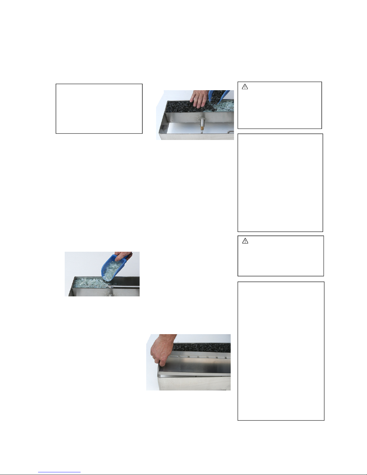
3. Evenly fill the media
compartment with burner
media (broken tempered
glass) fully covering the
burner as shown on a picture.
If you are NOT planning to
add optional topping media,
then fill the media
compartment in full and
proceed to the step 5.
NOTE: If you are planning to
add some topping media
(optional colored glass or
lava rock), leave approximately ¾” not filled on top
of burner media and proceed
to the next step.
4. Place and evenly distribute
topping media (optional
colored glass or lava rock) on
top of burner media as shown
on a picture.
Make sure that pilot opening
is not blocked with excess of
media.
5. Carefully leak test all
connections following the
procedure on page 5.
7. Cover manifold and valve
compartment of the Burner
Assembly with Front Cover.
8. Fill front cover tray with
topping media to desired
level.
INSTALLATION
CAUTION: Do not remove
the metal data plates
attached to the Linear
Burner System.
These plates contain
important information.
NOTICE: Installation and
repair should be done by a
qualified service person. The
appliance should be
inspected before use and at
least annually by a qualified
service person. More frequent cleaning may be
required as necessary. It is
imperative that control
compartment, burner and
circulating air passageways
of the appliance be kept
clean.
CLEARANCES TO
COMBUSTIBLE MATERIALS:
- Top……… 60” (153 cm)
- Short Side of the Unit
to Wall ……. . 9” (23 cm)
- Long Side of the Unit
to Wall …… 16” (41 cm)
No Thermal Floor Protection Required
Fuel pressure specification:
WARNING: Failure to position
the parts in accordance with
these diagrams or failure to
use only parts specially
approved with this appliance
may result in property
damage or personal injury.
WARNIN
G:
having the clear glass media
completely
covering
the burner!
Never light the
appliance
without
1. Remove Burner Assembly,
Front Cover and Burner
Media from packaging (see
Parts List, page
14).
6. Having free access to the
valve and manifold
compartment of the Burner
Assembly turn ON the
appliance following the
procedure on page
8.
Make sure the flame is even
along the burner and
appliance is fully operational
and safe for use. Turn OFF
the appliance and let it cool
before proceeding to the next
step.
Inlet
Nat. Gas
(NG)
Min:
4.5”
w.c.
Max:
10.5" w.c.
Inlet
Propane
(LP)
Min:
11.0”
w.c.
Max:
13.0" w.c.
Manifold (LP)
10.0” w.c.
Manifold (NG)
3.5” w.c.
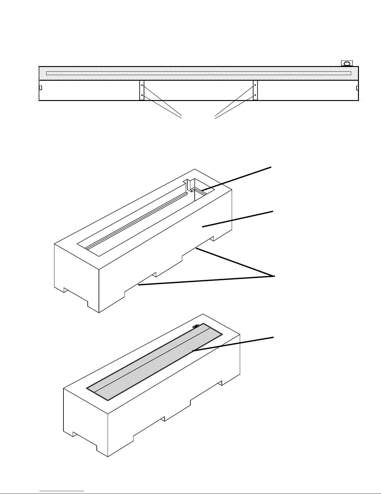
IMPORTANT: LBS-OD 96 models must have the burner system
secured to the base in order to avoid warpage of the appliance!
Secure burner
to base here
LINEAR BURNER SYSTEM OUTDOOR
INSTALLATION (EXAMPLE)
Clearances to combustibles must be
maintained (see page 3).
Minimum 0.75" lip to
support appliance.
Non-combustible materials
only (complete structure).
Allow for air flow
from below
( min. 12 Sq. In. per
linear foot of burner).
4
Cover
(see Illustrated Par ts L ist, page 13)
NOTE:
Maintain minimum 0.25" gap
around appliance and pilot.
Linear Burner System can be installed on any
non-combustible materials. Above example is
not a requirement.
must be in place when appliance is not in use.

FIREPLACE INSTALLATION
CHECK GAS TYPE
Use proper gas type for the replace you are installing. If you have conicting gas type, do not install replace. See dealer where
you purchased the replace for proper replace for your gas type or conversion kit.
INSTALLING GAS PIPING TO FIREPLACE / BURNER SYSTEM LOCATION
WARNING
A qualified installer or service person must
connect appliance to gas supply. Follow all
local codes.
CAUTION
For propane/LP units, never connect fireplace directly to the propane/LP supply. This
burner system requires an external regulator (not supplied). Install the external regulator
between the burner system and propane/LP supply.
INSTALLATION ITEMS NEEDED
Before installing replace and burner system, make sure you have the items listed below.
• External regulator (supplied by installer) • Piping (check local codes) • Sealant (resistant to propane/LP gas)
• Equipment shutoff valve* • Test gauge connection* • Sediment trap (recommended)
• Tee joint • Pipe wrench
• approved exible gas line with gas connector (if allowed by local codes — not provided)
* A CSA design-certied equipment shutoff valve with
1
/8" NPT tap is an acceptable alternative to test gauge connection.
Purchase the CSA design-certied equipment shutoff valve from your dealer.
For propane/LP connections only, the installer must supply an external regulator. The external regulator will reduce
incoming gas pressure. You must reduce incoming gas pressure to between 11 and 13 inches of water. If you do not reduce
incoming gas pressure, burner system regulator damage could occur. Install external regulator with the vent pointing down as
shown in Figure
1. Pointing the vent down protects it from freezing rain or sleet.
External
Regulator
100 lb. (min)
Propane/LP
Supply Tank
Vent Pointing
Down
CAUTION
Use only new black iron or steel pipe. Internally
tinned copper or copper tubing can be used per
National Fuel Code, section 2.6.3, providing gas
meets hydrogen sulfide limits, and where permitted
by local codes. Gas piping system must be sized
to provide minimum inlet pressure (listed on data
plate) at the maximum flow rate (BTU/hr). Undue
pressure loss will occur if the pipe is too small.
When using copper or ex connectors use only ttings approved
for gas connections. The gas control inlet is 3/8" NPT.
Figure 1 - External Regulator with Vent Pointing Down
(Propane/LP Only)
5

A.G.A. Design-Certified
Manual Shutoff Valve
With 1/8” NPT Tap
Cap Pipe Nipple Tee Joint
Sediment Trap
3” Minimum
CONNECTING TO GAS
SUPPLY
Installation Items Needed
pliers
- sediment trap
- tee joints
- pipe wrench
Installation must include a manual
shutoff valve, union, and plugged
1/8” NPT tap. Locate NPT tap
within reach for test gauge hook
up. NPT tap must be upstream
from the appliance.
Apply pipe joint sealant lightly to
male threads. This will prevent
excess sealant from going into
pipe. Excess sealant in pipe could
result in a clogged burner injector.
Install sediment trap in supply line
as shown below. Locate sediment
trap where it is within reach for
cleaning and trapped matter is not
likely to freeze. A sediment trap
CHECKING GAS
CONNECTION
Test Pressures in Excess Of
1/2 psi (3.5 kPa)
Test Pressures Equal To or
Less Than 1/2 psi (3.5 kPa)
WARNING:
A qualified
service person must connect appliance to gas supply. Follow all local codes.
CAUTION:
Use only new,
black iron or steel pipe.
Internally tinned copper
tubing may be used in
certain areas. Use pipe of
1/2" diameter or greater to
allow proper gas volume to
Linear Burner System. If
pipe is too small, undue loss
of pres
WARNIN
G:
Test all gas
piping and connections for
leaks after installing or
servicing. Correct all leaks
at once.
WARNING:
Never use an
open flame to check for a
leak. Apply a mixture of
liquid soap and water on all
joints. Bubbles forming
show a leak. Correct all
leaks at once.
From Gas Meter
(5” W.C. to 10.5” W.C.
pressure)
The appliance and its individual
shutoff valve must be disconnected from the gas supply piping
system during any pressure testing
of that system at test pressures in
excess of ½ psi (3.5 kPa).
The appliance must be isolated
from the gas supply piping system by
closing its individual manual
shutoff valve during any pressure
testing of the gas supply piping
system at test pressures equal to or
less than ½ psi (3.5 kPa).
Approved Flexible
Gas
Connector
IMPORTANT
This appliance is not designed
for use with a non-disposable,
self-contained LP-gas supply
system! Do not use a gas hose
to connect the appliance to any
gas supply. Use approved
Flexible Gas Connectors.
6
Before installing the Outdoor
Fireplace, make sure you have all
items listed bellow:
- piping (check local codes)
- sealant
- manual shutoff valve
- adjustable (crescent) wrench or
traps moisture and contaminants.
This keeps them from going into
Outdoor Fire
place controls.
If sediment trap is not installed or
is installed wrong, unit may not
run properly.
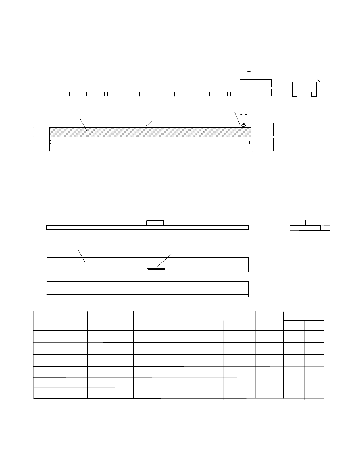
LINEAR BURNER SYSTEM OUTDOOR SPECIFICATIONS
BURNER DIMENSIONS
1.5"
7"
6"
PILOT
BURNER TUBE
4"
MEDIA BURNER TRAY
OVERAL WIDTH (W)
*
*
3"
11.5"
10"
4.25"
TOP COVER DIMENSIONS
4"
TOP COVER
2.5"
11.5"
WELD-ON HANDLE
1"
MODEL #
LBS-OD 24 - NG(LP)
LBS-OD 36 - NG(LP)
LBS-OD 48 - NG(LP)
LBS-OD 60 - NG(LP)
LBS-OD 72 - NG(LP)
LBS-OD 96 - NG(LP)
OVERALL
WIDTH
(W)
24"
36"
48"
60"
72"
96"
TOP COVER WIDTH (W+0.65")
BURNER TUBE
LENGTH
20"
32"
44"
56"
68"
92"
INPUT RATE (Btu/hr)
N.G. L.P.
41,000
61,000
82,000
102,000
116,000
142,000
33,500
54,000
72,000
90,000
110,000
146,500
# ORIF.
N.G. (L.P.)
2 (1)
3 (1)
4 (1)
5 (2
)
6 (2)
8 ( 2)
ORIF. SIZE
N.G. L.P.
44 49
44 4
4
3
38
43
43
43
36
41
35
3
7

LIGHTING INSTRUCTION
FOR YOUR SAFETY READ BEFORE OPERATING
LIGHTING FOR THE FIRST TIME
WARNING
Never use an open flame to check for gas leak.
If you do not follow these instruction exactly,
a fire or explosion may result causing property
damage, personal injury or loss of life.
A.This appliance is equipped with an ignition device which automatically lights the pilot. Do not try to light
the pilot by hand.
B. BEFORE OPERATING smell all around the appliance area for gas. Be sure to smell next to the oor because
some gas is heavier than air and will settle on the oor.
WHAT TO DO IF YOU SMELL GAS:
• Do not try to light any appliance.
• Do not touch any electric switch; do not use any phone in your building.
• Immediately call your gas supplier from a neighbor's phone.
Follow the gas supplier's instructions.
• If you cannot reach your gas supplier, call the fire department.
C. Main gas valve in this appliance is not serviceable and does not have any control knobs or switches to operate.
Do not remove heat shields covering the valve and electronic devices; do not try to repair or modify the valve
as it may result in a fire or explosion. Call a qualified service technician if you have any safety concerns.
D. Do not use this appliance if any part of it has been under water. Immediately call a qualied service technician
to inspect the appliance and to replace any part of the control system and any gas control that has been under
water.
INITIAL LIGHTING
Purge air from the supply line as follows:
• Open main shutoff valve.
• Unscrew main pressure test point.
• Leave inlet test screw open until gas comes in.
• When gas is owing, tighten inlet screw immediately.
LEAK TESTING
1. Follow the pipe from the gas supply line connection to the gas valve. Check connection for leaks with soap
and water mixture.
DANGER
2. Next check for gas leaks at the burner with soap and water mixture.
3. Check the pilot for gas leaks with soap and water mixture.
8

L100001 35
APPROVED LEAK TESTING METHOD
9
LIGHTING FOR THE FIRST TIME
Continued
You may check for gas leaks with the following methods only:
WARNING
• Soap and water solution
• An approved leak testing spray
• Electronic sniffer
WARNING
If using a soap and water solution to test
for leaks, DO NOT spray solution onto
electronic parts.
DANGER
Never use an open flame to check for gas leak.
Check for gas leaks in each of the following locations:
• Pipe from the gas supply line connection to the gas valve
• Burner connections, pilot • Field made joints / gas shutoff valve
• All joints on valve and control body • Factory made joints, each joint and connection
NOTE: Remove any excessive pipe compound from
the connections. Excessive pipe compound can set
off electronic sniffers.
OPERATING INSTRUCTIONS
1. STOP! Read the safety information on previous page.
2. Turn off all electric power to the appliance.
3. Do not attempt to light the pilot by hand.
4. Remove Front Tray from the appliance (see Illustrated Parts List, page 14).
5. Turn the gas control manual valve to the full OFF position.
6. Wait five (5) minutes to clear out any gas. Then smell for gas, including near the floor.
If you smell gas, STOP! Follow "B" in the safety information (see page 7).
If you don't smell gas, go to the next step.
7. Turn the gas control manual valve to the ON position.
8. Plug supplied 7V DC adapter into 110V power outlet.
9. Connect the wire to the DC input plug at the unit.
10. Lift and remove Heat Shield covering electronic components inside of the unit
11. Locate Remote Receiver inside of the unit
of the Receiver is in "REMOTE"
(middle) position.
(see Illustrated Parts List, page 13).
12. Replace Heat Shield and then replace Front Tray.
WA
(see Illustrated Parts List, page 13).
Make sure that the slider switch
13. Read and follow instructions in how to set up and to use remote control described in supplied
"INSTALLATION AND OPERATING INSTRUCTIONS FOR SKYTECH MODEL: 1001 T/LCD-A"".
14. If the appliance will not operate, follow the instructions "To Turn Off Gas To Appliance" and call
your service technician or gas supplier.

T
Continued
TO TURN OFF GAS TO APPLIANCE
Unplug 7V DC adapter from the power outlet.
3. Turn the gas control manual valve to the full OFF position.
1. Turn off all electric power to the appliance if service is to be
performed.
2. If necessary, remove Front Tray from the appliance to access
manual shutoff valve on gas line.
4. If necessary, replace Front Tray.
10
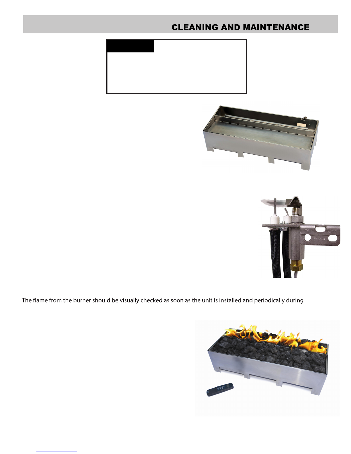
CLEANING AND MAINTENANCE
PILOT FLAME
The ames from the pilot should be visually checked as soon as the unit is installed
and periodically during normal operation. The pilot flame must always be present
when the fireplace is in operation or connected to the gas line with main shutoff
valve open and the IPS activated (powered). The pilot flame has two distinct
BURNER
1
flames, one engulfing the flame sensor and the other reaching to the main burner.
Pilot Flame
WARNING
Turn off gas before servicing fireplace. It
is recommended that a qualified service
technician perform these check-ups at the
beginning of each heating season.
BURNER, PILOT AND CONTROL COMPARTMENT
Keep the control compartment clean by vacuuming or brushing at
least twice a year. Make sure the burner porting, pilot air opening
and burner air opening are free of obstructions at all times.
normal operation.
Keep the appliance and its burner clean by vacuuming or brushing at
least twice a year. Make sure the burner porting and burner air
openings are free of obstructions at all times.
Inspect area around the burner. Remove any lint or foreign
material with a brush or vacuum.
The burner must be replaced prior to the appliance being put
into operation if it
refer to "Illustrated Parts List" for the replacement part number
specified by the manufacturer.
is evident that the burner is damaged. Please
11
TROUBLESHOOTING
WARNING: Turn off the unit
and let cool before servicing. Only
a qualified service person should
service and repair this appliance.
Note:
All troubleshooting items are listed in
order of operation.
OBSERVED PROBLEM POSSIBLE CAUSEREMEDY
Unit is smoking / sooting excessively
(
Note:
It is natural and unavoidable for
appliance sets to produce moderate
levels of carbon (soot) where flames
contact the media. This is especially true
Burner is excessively noisy
(
Note:
The movement and combustion of
gas will create low, unavoidable levels of
noise.)
Burner flame is too low or too high
Remote does not function
1. Poor fuel quality
2.Excessive flame impingement or blockage
3.Improper fuel/air mixture
1. Passage of air/gas across irregular surfaces
2. Excessive gas pressure on natural gas
units
1. Incorrect gas supply or pressure
2. Blocked burner orifice or burner manifold ports
3. Improper burner orifice size
1. Battery is not installed. Battery power
is low.
1.Contact local natural gas company
2.Separate the stones/media to allow
more flame passage
3.Remove any foreign items from the
flame pattern and/or check for proper
orifice sizing
1. Relieve any tight bends or kinks in gas
supply line
2.Check/reset gas regulator pressure
1. Check for proper gas supply pressure
2. Free burner orifice and manifold ports
of any burrs, paint, or other blockage
3. Verify proper burner orifice sizing (see
page 7)
1.Replace batteries in receiver and
remote control
12

Continued
OBSERVED PROBLEM
When ignitor button is pressed, there is
spark at pilot but no ignition
Burner does not light after pilot is lit
Delayed ignition burner
POSSIBLE CAUSE
1.Gas supply turned off or manual shutoff
valve closed shutoff valve
2.Air in gas lines when installed
3.Pilot adjustment screw closed
4.Pilot is clogged
5.Ignitor electrode broken
1.Burner orifice clogged
2.Inlet gas pressure is too low
3.Burner orifice diameter is too small
4.Flame sensor leads disconnected
1.Pilot flame needs adjusting
REMEDY
1.Turn on gas supply or open manual
2.Purge air from the supply line
(see page
3. Adjust pilot flame for approximately
1" blue flame
4.Clean pilot (see Cleaning and Mainte-
nance, page 1
5. Low gas pressure
1.Clean burner orifice
2.Contact local natural or propane/LP gas
company
3.Replace burner orifice
4.Reconnect leads
1.Adjust pilot flame for approximately
1" blue flame
8)
1) or replace pilot assembly.
WARNING: If you smell gas
• Shut off gas supply.
• Do not try to light any appliance.
• Do not touch any electrical switch; do not use any phone in
your building.
• Immediately call your gas supplier from a neighbor’s phone.
Follow the gas supplier’s instructions.
• If you cannot reach your gas supplier, call the fire department.
Unit produces unwanted odors
IMPORTANT:
Cleaning supplies, paint, paint remover, cigarette smoke, cements and glues, new
carpet or textiles, etc., create fumes. These fumes may mix with combustion air
and create odors. These odors will disappear over time.
Gas odor even when Remote Control is
leaks in OFF position
Operating unit where impurities in air exist may create odors.
1. Gas leak. See Warning statement above.
1.Gas leak. See Warning statement above.
2. Main gas valve defective 2. Replace gas valve
1. Locate and correct all leaks.
1. Locate and c o r r e c t al l
13
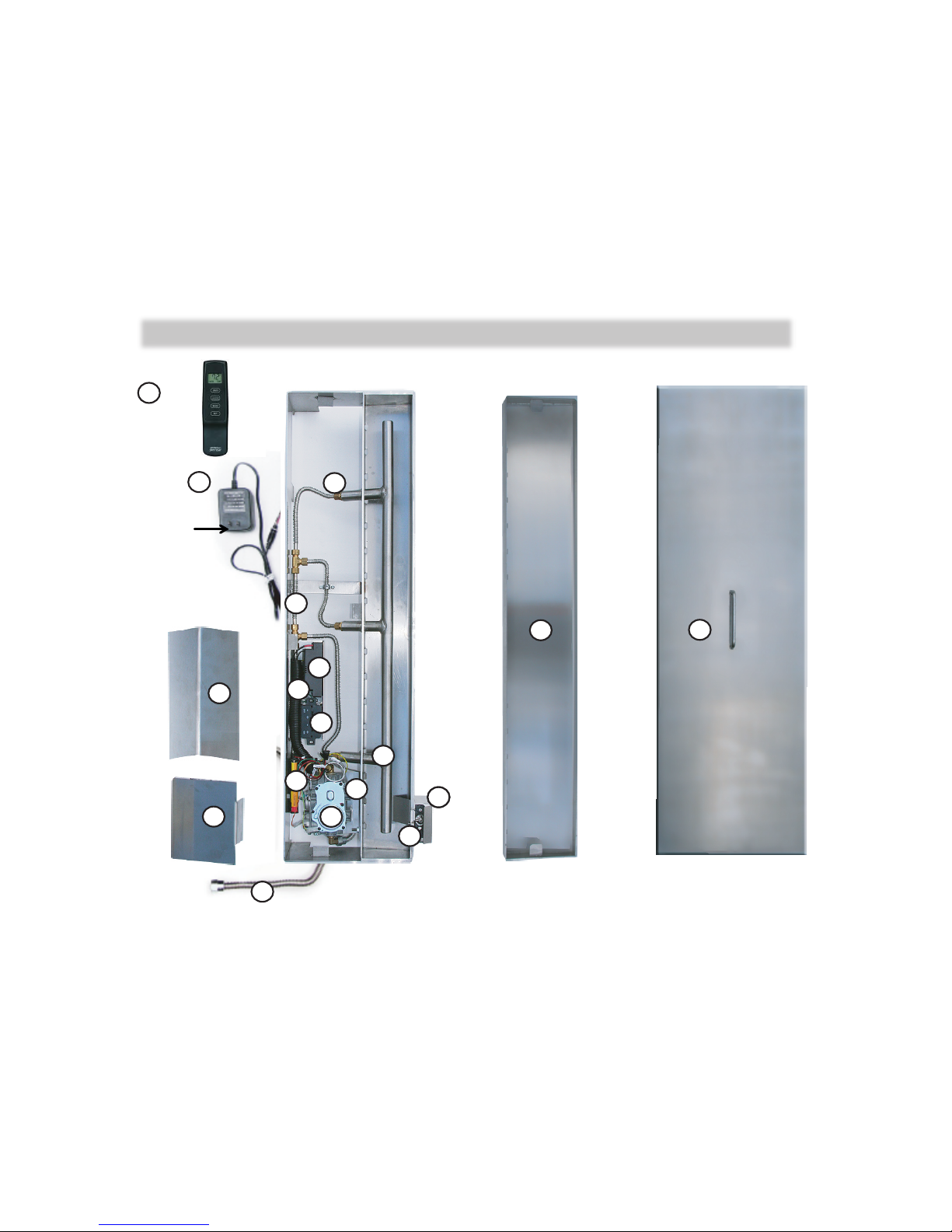
ILLUSTRATED PARTS LIST
O W N E R ’ S O P E R A T I ON A N D I N S T A LL AT IO N M A NU A L
14
ILLUSTRATED PARTS LISTILLUSTRATED PARTS LIST
FOR PART DESCRIPTION SEE NEXT PAGE
16
18
15
14
1
8
5
2
3
4
6
7
9
10
11
12
13
17
ILLUSTRATED PARTS LIST
8
W130202
W130204
W130206
W130208
1
7
Valve
Heat
Shield
D400261
D400261
D400261
D400261
1
4
Burner Flex Connector C100009
R100080
R100080
R100080 1
1
PARTS LIST
Key
#
Part Description
Q-
ty
Valve Bracket
(NOT SHOWN)
Manifold complete
with Tubing Assembly
Continued on Next Page
This list contains replaceable parts used in your
Linear Burner System Outdoor (LBS-OD)
appliance
1
Burner Assembly
W110202
W110204
W110206
W110208
1
2
Main Gas Valve
R10002
6
R10002
6
R10002
6
R10002
6 1
3
Pilot Assembly
R10002
8
R10002
8
R10002
8
R10002
8 1
5 DFC
Wire Assembly
H100141
H100141
H100141
H100141
1
6
D400260
D400260
D400260
D400260
1
Part Number according to the LBS-OD Natuaral Gas model (and Propane/LP)
(W120202)
(W120204)
(W120206)
(W120208)
(R100027)
(R100027)
(R100027)
(R100027)
(R100029)
(R100029)
(R100029)
(R100029)
(C100009)
(C100009)
(C100009)
(C100009)
LBS-OD 24 LBS-OD36 LBS-OD 48 LBS-OD 60 LBS-OD 72 LBS-OD 96
W120203
(W120203)
W120205
(W120205)
R100026
(R100027)
R100026
(R100027)
R100028
(R100029)
R100028
(R100029)
(C100009)
C100009
(C100009)
R100080
H100141
H100141
D400260
D400260
D400261
D400261
W130203
W130205
All replacement parts should be ordered from your
retai
ler or from
Spark Modern Fires
at
1-
866-938-3846 or on-line at www.sparkfires.com

1
PARTS LIST
(CONTINUED)
Key
#
Part Description
Q-
ty
9
Orifice
R100044
R100043
Top Media
(MANY
TYPES AVAILABLE)
Burner
Media
(NOT
SHOWN)
This list contains replaceable parts used in your
Linear Burner System Outdoor (LBS-OD)
appliance
Part Number according to the
LBS-
OD model
12 Pilot Shield
D400267
D400267
D400267
D400267
1
13 Control Heat Shield
D400265
D400265
D400265
D400265
1
14 DFC Board
H100142
H100142
H100142
H100142
1
(R200061)
(Air Mixer for LP model)
(R200063)
(R200063)
(D400290)
(D400290)
(D400290)
(D400290)
(1)
LBS-OD 24 LBS-OD36 LBS-OD 48 LBS-OD 60 LBS-OD 72 LBS-OD 96
R100044
(R200062)
R100043
R100043
R100043
SEE PAGE 6
(R200064)
(R100062)
10 Front Tray D400234 D400254 D400253 D400209 D400217 D400210 1
11 Unit Cover D400272 D400273 D400274 D400275 D400276 D400278 1
(D400290)
D400267
D400267
(D400290)
D4002
65
D400265
H1
00142
H1
00142
H100150
H100150
H100140
H100140
17 6 Volt Battery Pack
H100150
H100150
H100150
H100150
1
18 7V 10mA DC adapter H100140
H100140
H100140
H100140
1
Remote Control
15
Remote Receiver
RCB-R RCB-R RCB-R RCB-R RCB-R RCB-R 1
1
6 RCB RCB RCB RCB RCB RCB 1
19
xxx xxx xxx xxx xxx xxx Pkg
20 F200503 F200503
F200503 F200503 F200503 F200503 Pkg

ILLUSTRATED PARTS LIST
SEE NEXT PAGE
FOR PART DESCRIPTION
ILLUSTRATED PARTS LIST
SEE NEXT PAGE
FOR PART DESCRIPTION
2
ILLUSTRATED PARTS LIST
SEE NEXT PAGE
FOR PART DESCRIPTION
ILLUSTRATED PARTS LIST
SEE NEXT PAGE
FOR PART DESCRIPTION
2
17
PSE-NA368
Pilot Assembly
6 Volt Battery Backup ( uses 4 pcs AA Batteries)

L100001 17
127(6

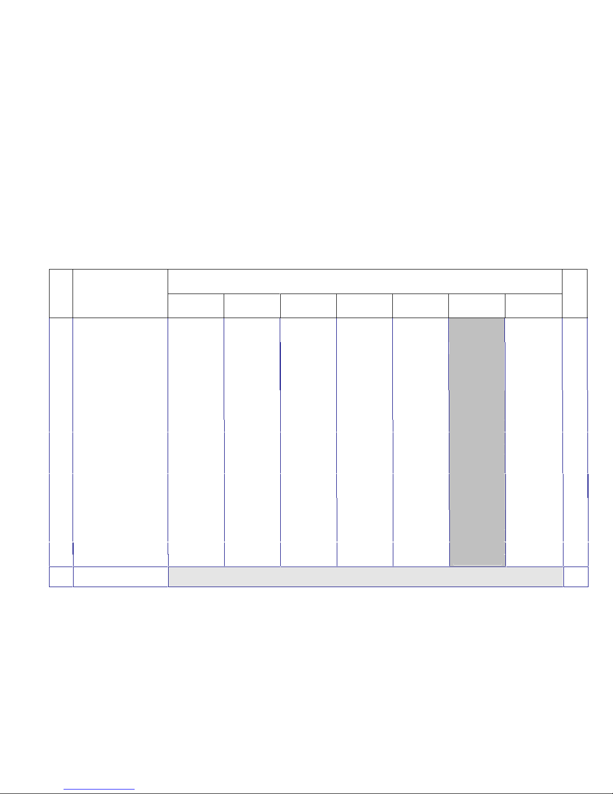
INSTALLATION RECORD
The installer should complete the form below that describes the details of the installation. Having this
written record of installation information available will greatly expedite trouble-shooting should any problem
arise with your fireplace. The installer should keep a duplicate of this form for their records. Accurate completion of this form is required for warranty coverage and for any technical support by Spark Modern Fires.
Date Purchased:
Purchaser/Dealer:
Installer:
Fireplace S/N on product ID tag:
Date Installed:
FUEL:
◯
Natural Gas
◯
◯
L.P. Propane
◯
Inlet Pressure Measured After Installation:
Manifold Pressure Measured After Installation:
High Fire:
In. W.C. Low Fire: In. W.C.
CONFIGURATION:
In. W.C.
ALTITUDE: Feet Above Sea Level
Was Fireplace Derated? ◯Yes ◯ No
If Yes To What Orifice Size?
Unusual Structure Near Appliance?
◯
Inside Corner
◯
Termination:
◯
Trees/Shrubs
◯
(Please Describe)
Prevalent Wind Conditions?
Other Installation Notes:
◯
◯
Other
SMF32011

LIMITED LIFETIME WARRANTY
The following components are warranted for life to the original owner, subject to proof of purchase: Linear
Burner Assembly.
BASIC WARRANTY
Spark Modern Fires warrants the components and materials in your gas appliance to be free from manufacturing
and material defects for a period of two years from date of installation. After installation, if any of the components manufactured by Spark Modern Fires in the appliance are found to be defective in materials or workmanship, Spark Modern Fires will, at its option, replace or repair the defective components at no charge to the original owner. Spark Modern Fires will also pay for reasonable labor cost incurred in replacing or repairing such components for a period of two years from date of installation. Any products presented for warranty repair must be
accompanied by a dated proof of purchase.
This Limited Lifetime Warranty will be void if the appliance is not installed by a qualified installer in accordance with installation instructions. The Limited Lifetime Warranty will also be void if the appliance is not ope-
rated and maintained according to the operating instructions supplied with the appliance, and does not extend to (1)
firebox/burner assembly damaged by accident, neglet, misuse, abuse, alterations, negligence of others, including the installation thereof by unqualified installers, (2) the costs of removal, reinstallation or transportation of
defective parts on the appliance, or (3) incidental or consequential damage. All service work must be performed
by an authorized service representative.
This warranty is expressly in lieu of other warranties, express or implied, including the warranty of merchantability of fitness for purpose and of all other obligations or liabilities. Spark Modern Fires does not assume for it
any other obligations or liabilities in connection with sale or use of the appliance. In states that do not allow limitations on how long an implied warranty lasts, or do not allow exclusion of indirect damage, those limitations of
exclusions may not apply to you. You may also have additional right not covered in the Limited Lifetime War-
ranty. Spark Modern Fires reserves the right to investigate any and all the claims against this Warranty and de-
cide upon method of settlement. For information about this warranty contact:
Spark Modern Fires
53 Chestnut Woods Rd.
Redding, CT 06896
U.S.A.
WARRANTY INFORMATION
KEEP THIS FOR WARRANTY
Model
Serial No.
Date Purchased
Always specify model and serial numbers when communicating with the factory.
Rev.7 08/2013
 Loading...