

Spark modern fires FIRE RIBBON 53 FR-N, FIRE RIBBON 53 FR-P Owner's Operation And Installation Manual

Save this manual for future reference.
WARNING: If the information in this manual is not followed exactly, a fire or explosion may result causing
property damage, personal injury or loss of life.
— Do not store or use gasoline or other
vapors and liquids in the vicinity of this or any other
appliance.
— WHAT TO DO IF YOU SMELL GAS
• Do not try to light any appliance.
• Do not touch any electrical switch; do not use any
phone in your building.
• Immediately call your gas supplier from a neighbor’s
phone. Follow the gas supplier’s instructions.
• If you cannot reach your gas supplier, call the fire
department.
— Installation and service must be performed by a quali-
ed installer, service agency or the gas supplier.
UNVENTED (VENT-FREE) GAS FIREPLACE
OWNER’S OPERATION AND INSTALLATION MANUAL
SPARK MODERN FIRES
MODEL 53
FR-N , FR-P
FIRE RIBBON
™

WARNING: Improper installation, adjustment, alteration, service or maintenance can cause injury or property damage. Refer to this manual for correct installation
and operational procedures. For assistance or addi-
tional information consult a qualified installer, service
agency or the gas supplier.
WARNING: This is an unvented gas-fired heater. It uses
air (oxygen) from the room in which it is installed. Provisions for adequate combustion and ventilation air must
be provided. Refer to Air for Combustion and Ventilation
section of this manual.
This appliance may be installed in an aftermarket*, permanently located, manufactured (mobile) home, where
not prohibited by local codes.
This appliance is only for use with the type of gas indicated on the rating plate. This appliance is not convertible for use with other gases.
*Aftermarket: Completion of sale, not for purpose of resale, from the manufacturer
TABLE OF CONTENTS
Safety Information .............................................. 3
Local Codes ....................................................... 4
Locating Firebox ................................................ 5
Product Specifications........................................ 5
Air For Combustion and Ventilation ................... 6
Installation .......................................................... 8
Operating Fireplace .......................................... 17
Inspecting Burners ........................................... 19
Cleaning and Maintenance ................................ 20
Wiring Diagram .................................................. 21
Specifications ..................................................... 21
Troubleshooting ................................................. 22
Illustrated Parts Breakdown and Parts List ........ 26
Warranty Information ....................................Back Cover
This fireplace has been tested and approved by OMNI-Test
laboratories, Inc. under ANSI Z21.11.2b-2004 Unvented
Gas-Fired Room Heaters
Framing ............................................................. 11

3
SAFETY INFORMATION
WARNING: This product contains and/or generates chemicals
known to the state of California
to cause cancer or birth defects
or other reproductive harm.
IMPORTANT: Read this owner’s
manual carefully and completely
before trying to assemble,
operate or service this heater.
Improper use of this heater can
cause serious injury or death
from burns, fire, explosion,
electrical shock and carbon
monoxide poisoning.
DANGER: Carbon monoxide
poisoning may lead to death!
Carbon Monoxide Poisoning: Early signs of
carbon monoxide poisoning resemble the flu, with
headaches, dizziness or nausea. If you have these
signs, the heater may not be working properly. Get
fresh air at once! Have heater serviced. Some
people are more affected by carbon monoxide than
others. These include pregnant women, people with
heart or lung disease or anemia, those under the
influence of alcohol and those at high altitudes.
Natural and Propane/LP Gas: Natural and pro-
pane/LP gases are odorless. An odor-making agent
is added to the gas. The odor helps you detect a gas
leak. However, the odor added to the gas can fade.
Gas may be present even though no odor exists.
Make certain you read and understand all warnings.
Keep this manual for reference. It is your guide to
safe and proper operation of this heater.
WARNING: Any change to
this heater or its controls can
be dangerous.
WARNING: Do not use a
blower insert, heat exchanger
insert or other accessory not approved for use with this heater.
WARNING: Do not allow fans
to blow directly into the fireplace.
Avoid any drafts that alter burner
flame patterns. Ceiling fans can
create drafts that alter burner
flame patterns. Altered burner
patterns can cause sooting.
Due
to high temperatures, the
appliance should be located out
of traffic and away from furniture
and draperies.
Do
not place clothing or other
flammable material on or near
the appliance. Never place any
objects on the heater.
Fireplace front becomes very
hot when running fireplace.
Keep children and adults away
from hot surfaces to avoid
burns or clothing ignition. Fireplace will remain hot for a time
after shutdown. Allow surfaces
to cool before touching.
Carefully supervise young children when they are in the room
with fireplace. When using the
optional hand-held remote accessory, keep selector switch
inside firebox in the OFF posi-
tion to prevent children from turning on burners with remote.
Keep the appliance area clear
and free from combustible materials, gasoline and other flammable vapors and liquids.

4
1.
This appliance is only for use with the type of
gas indicated on the rating plate. This appliance
is not convertible for use with other gases.
2. Do not place propane/LP supply tank(s) inside any structure. Locate propane/LP supply
tank(s) outdoors (propane/LP units only).
3. If you smell gas
• shut off gas supply
• do not try to light any appliance
• do not touch any electrical switch; do not use
any phone in your building
•
immediately
call your gas supplier from a
neighborʼs phone. Follow the gas supplierʼs
instructions
•
if
you cannot reach your gas supplier, call
the fire department
4. This fireplace shall not be installed in a bedroom or bathroom.
5.
Do not use this fireplace as a wood-burning
fireplace.
6. To prevent the creation of soot, follow the
instructions in Cleaning and Maintenance
section.
7. Before using furniture polish, wax, carpet
cleaner
or
similar products, turn heater off. If
heated, the vapors from these products may
create a white powder residue within burner
box or on adjacent walls or furniture.
8.
This fireplace needs fresh air ventilation to run
properly. This fireplace has an Oxygen Depleti
on Sensing (ODS) safety shutoff system. The
ODS shuts down the fireplace if enough fresh
air is not available. See Air for Combustion
and Ventilation, page 6. If fireplace keeps
shutting off, see Troubleshooting, page 21.
9. Do not run fireplace
• where flammable liquids or vapors are used
or stored
•
under dusty conditions
1
0. Do not use this fireplace to cook food or burn
paper or other objects.
SAFETY INFORMATION
Continued
11. Do not use fireplace if any part has been
exposed to or under water. Immediately call
a qualified service technician to inspect the
fireplace and to replace any part of the control
system and any gas control which has been
under water.
12. Turn fireplace off and let cool before servicing.
Only a qualified service person should service
and repair fireplace.
13. Operating fireplace above elevations of 4,500
feet could cause pilot outage.
14.
To prevent performance problems in propane/LP
units, do not use propane/LP fuel tanks of less
than 100 lbs. capacity (propane/LP units only).
15.
Provide adequate clearances around air
openings.
LOCAL CODES
Install and use fireplace with care. Follow all local
codes. In the absence of local codes, use the latest edition of The National Fuel Gas Code ANSI
Z223.1/NFPA 54*.
*Available from:
American National Standards Institute, Inc.
1430 Broadway
New
Y
ork, NY 10018
National Fire Protection Association, Inc.
Batterymarch Park
Quincy, MA
02269
St
ate of Massachusetts: The installa-
t
i
on must be made by a licensed plumber
or gas fitter in the Commonwealth of
Massachusetts.
Sellers of unvented propane or natural
gas-fired supplemental room heaters shall
provide to each purchaser a copy of 527
CMR 30 upon sale of the unit.
Vent-free gas products are prohibited for
bedroom and bathroom installation in the
Commonwealth of Massachusetts.
WARNING: Do not allow fans
to blow directly into the fireplace.
Avoid any drafts that alter burner
flame patterns. Ceiling fans can
create drafts that alter burner
flame patterns. Altered burner
patterns can cause sooting.
Keep the appliance area clear
and free from combustible materials, gasoline and other flammable vapors and liquids.

5
LOCATING FIREBOX
PLANNING
Plan where you will install the firebox. This will save time and money later when you install the firebox.
Before installation, consider the following:
1. Where the firebox will be located. Allow for wall and ceiling clearances (see Installation Clear-
ances, page 9.
2. Everything needed to complete installation.
3. Proper air for combustion and ventilation.
PRODUCT SPECIFICATIONS
FIRE RIBBON - VENT FREE
FRONT VIEW
36"
11"
2"
RIGHT SIDE VIEW
8.15"
18"
28.6"
31.1"
TOP VIEW
0.750"
12"
41"
18"
GAS LINE ACCESS, BOTH SIDES
5.50"
5"

6
AIR FOR COMBUSTION
AND VENTILATION
WARNING: This firebox shall
not be installed in a confined
space or unusually tight construction unless provisions are
provided for adequate combustion and ventilation air. Read the
following instructions to insure
proper fresh air for this and
other fuel-burning appliances
in your home.
Todayʼs homes are built more energy efficient
than ever. New materials, increased insulation and
new construction methods help reduce heat loss
in homes. Home owners weather strip and caulk
around windows and doors to keep the cold air out
and the warm air in. During heating months, home
owners want their homes as airtight as possible.
While it is good to make your home energy efficient, your
home needs to breathe. Fresh air must
enter your home. All fuel-burning appliances need
fresh air for proper combustion and ventilation.
Exhaust fans, fireboxes, clothes dryers and fuel
burning appliances draw air from the house to
operate. You must provide adequate fresh air for
these appliances. This will insure proper venting
of vented fuel-burning appliances.
PROVIDING ADEQUATE
VENTILATION
The following are excerpts from National Fuel
Gas Code, ANSI Z223.1/NFPA 54, Section 5.3,
Air for Combustion and Ventilation.
All spaces in homes fall into one of the three following ventilation classifications:
1.
Unusually Tight Construction
2. Unconfined Space
3. Confined Space
The information on pages 8 through 15 will help
you classify your space and provide adequate
ventilation.
Unusually T
ight Construction
The air that leaks around doors and windows
may provide enough fresh air for combustion and
ventilation. However, in buildings of unusually
tight construction, you must provide additional
fresh air.
Unusually tight construction is defined as
construction where:
a. walls and ceilings exposed to the out-
si
de atmosphere have a continuous
water vapor retarder with a rating of
one perm (6 x 10
-11
kg per pa-sec-m2) or
less with openings gasketed or sealed
and
b. weather stripping has been added on
openable windows and doors and
c. c
aulking or sealants are applied to
areas such as joints around window
and door frames, between sole plates
and floors, between wall-ceiling joints,
between wall panels, at penetrations
for plumbing, electrical and gas lines
and at other openings.
If your
home meets all of the three criteria
above, you must provide additional fresh
air. See Ventilation Air From Outdoors,
page 8.
If your home does not meet all of the three
criteria above, proceed to Determining
Fresh-Air Flow for Heater Location, page 7.
Confined and Unconfined Space
The National Fuel Gas Code, ANSI Z223.1/NFPA
54 defines a confined space as a space whose
volume is less than 50 cubic feet per 1,000 Btu
per hour (4.8 m3 per kw) of the aggregate input
rating of all appliances installed in that space and
an unconfined space as a space whose volume is
not less than 50 cubic feet per 1,000 Btu per hour
(4.8 m3 per kw) of the aggregate input rating of
all appliances installed in that space. Rooms communicating directly with the space in which the
appliances are installed*, through openings not
furnished with doors, are considered a part of the
unconfined space.
* Adjoining rooms are communicating only if
there are doorless passageways or ventilation grills
between them.

7
AIR FOR COMBUSTION
AND VENTILATION
Continued
DETERMINING FRESH-AIR FLOW
FOR HEA
TER LOCATION
Determining if You Have a Confined or
Unconfined Space
Use this work sheet to determine if you have a
confined or unconfined space.
Space: Includes the room in which you will
install heater plus any adjoining rooms with doorl
ess passageways or ventilation grills between
the rooms.
1. Determine the volume of the space (length x
width x height).
Length x Width x Height =__________cu. ft.
(volume of space)
E
xample: Space size 22 ft. (length) x 18 ft.
(width) x 8 ft. (ceiling height) = 3168 cu. ft.
(volume of space)
If additional ventilation to adjoining room is
supplied with grills or openings, add the volume
of these rooms to the total volume of the space.
2.
Multiply the space volume by 20 to determine
the maximum Btu/Hr the space can support.
__________ (volume of space) x 20 = (Maxi-
mum Btu/Hr the space can support)
E
xample: 3168 cu. ft. (volume of space) x 20 =
63,360 (maximum Btu/Hr the space can support)
3. Add the Btu/Hr of all fuel burning appliances in
the space.
Vent-free fireplace ___________ Btu/Hr
Gas water heater* ___________ Btu/Hr
Gas furnace ___________ Btu/Hr
Vented gas heater ___________ Btu/Hr
Gas fireplace logs ___________ Btu/Hr
Other gas appliances* + __________ Btu/Hr
Total = __________ Btu/Hr
* Do not include direct-vent gas appliances. Dir
ect-vent draws combustion air from the outdoors
and vents to the outdoors.
Example:
Gas water heater __________ Btu/Hr
Vent-free fireplace + ________ Btu/Hr
Total = ________ Btu/Hr
4.
Compare the maximum Btu/Hr the space can
support with the actual amount of Btu/Hr used.
_________
Btu/Hr (maximum the space can support)
_________
Btu/Hr (actual amount of Btu/Hr used)
Example: 63,360 Btu/Hr (maximum the space
can support)
79,000 Btu/Hr (actual amount of
Btu/Hr used)
The
space in the above example is a confined space
because the actual Btu/Hr used is more than the maxim
um Btu/Hr the space can support. You must provide
additional fresh air. Your options are as follows:
A. Rework worksheet, adding the space of an adjoin-
i
ng room. If the extra space provides an unconfined
space, remove door to adjoining room or add
ventilation grills between rooms. See Ventilation
Air From Inside Building, page 8.
B. Vent room directly to the outdoors. See Ventila-
tion
Air From Outdoors, page 8.
C. Install a lower Btu/Hr fireplace, if lower Btu/Hr
size makes room unconfined.
If the actual Btu/Hr used is less than the maximum Btu/Hr the space can support, the space is
an unconfined space. You will need no additional
fresh air ventilation.
WARNING: If the area in which
the heater may be operated is
smaller than that defined as
an unconfined space or if the
building is of unusually tight
construction, provide adequate
combustion and ventilation air
by one of the methods described
in the National Fuel Gas Code,
ANSI Z223.1/NFPA 54 Section 5.3
or applicable local codes.
40,000
39,000
79,000

8
VENTILATION AIR
Ventilation Air From Inside Building
This fresh air would come from an adjoining unconfined space. When ventilating to an adjoining
unconfined space, you must provide two permanent openings: one within 12" of the ceiling and
one within 12" of the floor on the wall connecting
the two spaces (see options 1 and 2, Figure 1). You
can also remove door into adjoining room (see
option 3, Figure 1). Follow the National Fuel Gas
Code, ANSI Z223.1/NFPA 54, Section 5.3, Air for
Combustion and Ventilation for required size of
ventilation grills or ducts.
AIR FOR COMBUSTION
AND VENTILATION
Continued
Ventilation Air From Outdoors
Provide extra fresh air by using ventilation grills or
ducts. You must provide two permanent openings:
one within 12" of the ceiling and one within 12"
of the floor. Connect these items directly to the
outdoors or spaces open to the outdoors. These
spaces include attics and crawl spaces. Follow the
National Fuel Gas Code, ANSI Z223.1/NFPA 54,
Section 5.3, Air for Combustion and Ventilation for
required size of ventilation grills or ducts.
IMPORTANT: Do not provide openings for inlet
or outlet air into attic if attic has a thermostatcontrolled power vent. Heated air entering the attic
will activate the power vent.
Figure 2
- Ventilation Air from Outdoors
Figure 1 - Ventilation Air from Inside
Building
Outlet
Air
Ventilated
Attic
Outlet
A
ir
Inlet
Air
Inlet Air
Ve
ntilated
Crawl Space
T
o
Crawl
Space
To Attic
INSTALLATION
NOTICE: This heater is intended
for use as supplemental heat.
Use this heater along with your
primary heating system. Do not
install this heater as your primary heat
source. If you have a
central heating system, you may
run system’s circulating blower
while using heater. This will help
circulate the heat throughout the
house. In the event of a power
outage, you can use this heater
as your primary heat source.
WARNING: A qualified service
person must install fireplace.
Follow all local codes.
WARNING: Never install the
fireplace
• in a bedroom or bathroom
• in a recreational vehicle
• where curtains, furniture,
clothing or other flammable
objects are less than 42 inches
from the front, top or sides of
the heater
• in high traffic areas
• in windy or drafty areas
12
12
Ventilation Grills
Into Adjoining
Room, Option 2
Ventilation Grills
Into Adjoining
Room,
Option 1
Or
Remove
Door into
Adjoining
Room,
Option 3
"
"

9
CAUTION: This fireplace creates warm air currents. These
currents move heat to wall surfaces next to fireplace. Installing
fireplace next to vinyl or cloth
wall coverings or operating
heater where impurities (such
as, but not limited, to tobacco
smoke, aromatic candles, cleaning fluids, oil or kerosene lamps,
etc.) in the air exist, may discolor
walls or cause odors.
Note: Your fireplace is designed to be used in zero
clearance installations. Wall or framing material
can be placed directly against any exterior surface
on the rear, sides or top of your fireplace, except
where standoff spacers are integrally attached. If
standoff spacers are attached to your fireplace,
these spacers can be placed directly against wall
or framing materials.
Use the dimensions shown for rough openings to
create the easiest installation. See Built-In Fire-
place Installation, page
10.
IMPORTANT: Vent-free heaters add moisture to
the air. Although this is beneficial, installing firep
lace in rooms without enough ventilation air may
cause mildew to form from too much moisture. See
Air for Combustion and Ventilation, page 6.
IMPORTANT: Make sure the fireplace is level.
If fireplace is not level, it will not work
properly.
CHECK GAS TYPE
Use the correct gas type (natural or propane/LP)
for your fireplace. If your gas supply is not correct, do not install fireplace. Call dealer where you
bought fireplace for proper type fireplace.
WARNING: This appliance
is equipped for (natural or propane/LP) gas. Field conversion
is not permitted.
INSTALLATION
Continued
INSTALLATION CLEARANCES
WARNING: Maintain the
minimum clearances. If you
can, provide greater clearances
from floor, ceiling and adjoining
wall.
Carefully follow the instructions below. This will
ensure safe installation.
Minimum Wall and Ceiling Clearances
A. Clearances from the side of the fireplace
cabinet to any combustible material and wall
should follow diagram in Figure 3.
Example: The face of a mantel, bookshelf,
etc. is made of combustible material and
protrudes 3 1/2" from the wall. This combustible material must be 4" from the side of the
fireplace cabinet (see Figure 3).
B. Clearances from the top of the firebox open-
ing
to the ceiling should not be less than 42
inches.
C.
When the firebox is installed on carpeting or
other combustible material, other than wood
flooring, the firebox should be installed on a
metal or wood panel extending the full width
and depth of the enclosure.
D.
Clearances from the bottom of firebox to the
floor is 0 inches.
CAUTION: Do not install the
firebox directly on carpet or
vinyl.
*Minimum 16 inches from Side Wall
*
Example
Figure 3 - Minimum Clearance for
Combustible to Wall

10
INSTALLATION
Continued
NOTICE: Surface temperatures
of adjacent walls and mantels become hot during operation. Walls
and mantels above the firebox
may become hot to the touch.
If installed properly, these temperatures meet the requirement
of the national product standard.
Follow all minimum clearances
shown in this manual.
IMPORTANT: Allow for a minimum space of 1/2" x 12" for air
flow to the front louvers of the
fireplace from below when covering the face.
PLEASE NOTE: Framing may need to be recessed from 3/4" to 1-1/2" depending on layers and type of facing material used during installation.
INSTALLING GAS PIPING TO
FIREPLACE LOCATION
WARNING: This appliance
requires a 1/2" NPT (National
Pipe Thread) inlet connection to
the pressure regulator.
WARNING: A qualified service
person must connect fireplace
to gas supply. Follow all local
codes.
CAUTION: Never connect propane/LP fireplace directly to the
propane/LP supply. This fireplace
requires an external regulator
(not supplied). Install the external
regulator between the fireplace
and propane/LP supply.
INSIDE CHASE INSTALLATION
42"
41"
18.5"
41"
RECESSED INSTALLATION
18.5"
0.50"
42"
0.50"
VENT FREE FIRE RIBBON
FRAMING DIMENSIONS
0.75"
31.50"
0.50"
42.00"
FASTENING TABS IN USE
VENT FREE FIRE RIBBON
FACING DIMENSIONS
MINIMUM NON COMBUSTIBLE MATERIALS
COMBUSTIBLE
MATERIAL
NON COMBUSTIBLE
MATERIAL AREA
29.00"
42.00"

11
Figure 4.1 - Installation of facing materials ( Case #1)
ALLOW AIRFLOW THRU GRILLE
LEAVE THE LOUVER AREA CLEAR AND ATTACH GRILLE HERE.
IE: DUROCK, CEMENT BOARD, GRANITE,
MARBLE, STONE
FIRE RIBBON FACING
WITH ONE LAYER
OF NON-COMBUSTIBLE
MATERIAL
OPTION 1
THREE WAYS TO ALLOW AIR FLOW TO FRONT AIR VENT
NON COMBUSTIBLE MATERIAL
minimum 42" wide X 29" high
NON COMBUSTIBLE MATERIAL
min 42"
min 29"

12
Figure 4.2 - Installation of facing materials ( Case #2)
COVER WITH SECOND LAYER OF FACE MATERIAL.
SECOND LAYER
LEAVE THE LOUVER AREA CLEAR WITH FIRST LAYER OF FACE MATERIAL
FIRST LAYER
TOP VIEW
ALLOW AIRFLOW
SIDE VIEW
ALLOW AIRFLOW
FIRE RIBBON FACING
WITH TWO LAYERS
OF NON-COMBUSTIBLE
MATERIALS
IE: DUROCK, CEMENT BOARD, GRANITE,
MARBLE, STONE
ALLOW FOR MINIMUM 6 SQUARE INCHES OF AIR FLOW.
ALLOW FOR MINIMUM 6 SQUARE INCHES OF AIR FLOW.
OPTION 2
NON COMBUSTIBLE MATERIAL
minimum 42" wide X 29" high
NON COMBUSTIBLE MATERIAL
min 29"
min 42"
min 42"
min 29"

13
Figure 4.3 - Installation of facing materials ( Case #3)
FIRE RIBBON FACING
WITH THICK LAYER
OF NON-COMBUSTIBLE
MATERIAL
ALLOWING AIR FLOW FROM BEHIND SURROUND
OPTION 3
ALLOW FOR MINIMUM 6 SQUARE INCHES OF AIR FLOW
NON COMBUSTIBLE
AIRFLOW FROM BEHIND
SURROUND INTO AIR VENT
SIDE VIEW
VIEW FROM BACK OF SURROUND
NON COMBUSTIBLE
NOTCH OUT BACK OF FACE MATERIAL.
ALLOW FOR MINIMUM 6 SQUARE INCHES OF AIR FLOW

14
INSTALLATION
Continued
WARNING: Never connect
natural gas fireplace to private
(non-utility) gas wells. This
gas is commonly known as
wellhead gas.
Installation Items Needed
Before installing fireplace, make sure you have
the items listed below.
• external regulator for propane/LP unit only
(supplied by installer)
• piping (check local codes)
•
sealant (resistant to propane/LP gas)
• equipment shutoff valve *
• test gauge connection *
• sediment trap (optional)
• tee joint
• pipe wrench
• approved flexible gas line with gas connector
(if allowed by local codes) (not provided)
with
1/8" NPT tap is an acceptable alternative to
test gauge connection. Purchase the optional CSA
design-certified equipment shutoff valve from your
dealer.
Fo
r propane/LP units, the installer must supply
an external regulator. The external regulator will
reduce incoming gas pressure. You must reduce
incoming gas pressure to between 11 and 14 inches
of water. If you do not reduce incoming gas pressure, heater
regulator damage could occur. Install
external regulator with the vent pointing down
as shown in Figure 5. Pointing the vent down
protects it from freezing rain or sleet.
* Purchase the optional CSA design-certified
equipment shutoff valve from your dealer.
** Minimum
inlet pressure for purpose of input
adjustment.
Figure 6 - Gas Connection
Sediment Trap
CSA Design-Certified
Equipment Shutoff Valve
With 1/8" NPT Tap*
3" Minimum
Cap Pipe Tee
Nipple Joint
Natural Gas
From Gas Meter
(5" W.C.** to 10.5"
W.C. Pressure)
Propane/LP
From External
Regulator
(11" W.C.** to 14"
W.C. Pressure)
CAUTION: Use only new,
black iron or steel pipe. Internally-tinned copper
tubing may
be used in certain areas. Check
your local codes. Use pipe of
1/2" diameter or greater to allow
proper gas volume to fireplace.
If pipe is too small, undue loss
of volume will occur.
Installation must include an equipment shutoff
valve, union and plugged 1/8" NPT tap. Locate
NPT tap within reach for test gauge hook up.
NPT tap must be upstream from fireplace.
IMPO
RTANT:
Install equipment shutoff valve
in an accessible location. The equipment shutoff
valve
is for turning on or shutting off the gas to
the appliance.
Check your building codes for any special requirements for locating equipment shutoff valve
to fireplaces.
Ap
ply pipe joint sealant lightly to male NPT
threads. This will prevent excess sealant from
going into pipe. Excess sealant in pipe could result
in clogged fireplace valves. Never use sealant on
flare threads.
Propane/LP
Supply Tank
External
Regulator
Figure 5 - External Regulator
W
ith Vent
Pointing Down
Vent
Pointing
Down
SHUTOFF VALVE

15
NOTICE: Most building codes
do not permit concealed gas
connections. A flexible gas line
is provided to allow accessibility
from the fireplace (see Figure 7).
The flexible gas supply line connection to the equipment shutoff
valve should be accessible.
INSTALLATION
Continued
Figure 7 - Attaching Flexible Gas Lines
Together
Flexible Gas Line
from Fireplace
Gas Regulator
To Fireplace
Gas Regulator
Equipment
Shutoff Valve
Provided by
Installer
Propane/LP
To External
Regulator
Natural Gas
To Gas Meter
WARNING: Use pipe joint
sealant that is resistant to liquid
petroleum (LP) gas.
We recommend that you install a sediment trap in
supply line as shown in Figure 6, page 12. Locate
sediment trap where it is within reach for cleaning.
Install in piping system between fuel supply
and fireplace. Locate sediment trap where trapped
matter is not likely to freeze. A sediment trap traps
moisture and contaminants. This keeps them from
going into fireplace gas controls. If sediment trap
is not installed or is installed wrong, fireplace may
not run properly.
CONNECTING FIREPLACE TO GAS
SUPPLY
1. Remove access panel.
2. Route gas line (provided by installer) from
equipment shutoff valve to fireplace. Route
flexible gas supply line through one of the
access holes.
3. Attach the flexible gas line to gas supply as
p
er Figure 7. Check tightness of flexible gas
line attached to gas regulator of fireplace and
check all gas connections for leaks ( see
Checking Gas Connections, page 16).

16
CHECKING GAS CONNECTIONS
WARNING: Test all gas pip-
ing and connections, internal
and external to unit, for leaks
after installing or servicing. Correct all leaks at once.
WARNING: Never use an
open flame to check for a leak.
Apply a noncorrosive leak
detection fluid to all joints.
Bubbles forming show a leak.
Correct all leaks at once.
CAUTION: Make sure exter-
nal regulator has been installed
between propane/LP supply and
fireplace. See guidelines under
Connecting Fireplace to Gas
Supply.
PRESSURE TESTING GAS SUPPLY
PIPING SYSTEM
Test Pressures In Excess Of 1/2 PSIG
(3.5 kPa)
1.
Disconnect
fireplace with its main gas valve
(control valve) and equipment shutoff valve
from gas supply piping system. Pressures
in excess of 1/2 psig will damage fireplace
regulator.
2. Cap off open end of gas pipe where equipment
shutoff valve was connected.
3. Pressurize supply piping system by either
opening propane/LP supply tank valve for
propane/LP gas or opening main gas valve
located on or near gas meter for natural gas
or using compressed air.
4. Check all joints of gas supply piping system.
Apply noncorrosive leak detection fluid to all
joints. Bubbles forming show a leak.
5.
Correct all leaks at once.
6.
Reconnect fireplace and equipment shutoff
valve to gas supply. Check reconnected fittings
for leaks.
INSTALLATION
Continued
Figure 8 - Equipment Shutoff Valve
Open
Closed
Equipment
Shutoff V
alve
Test Pressures Equal To or Less Than
1/2 PSIG (3.5 kPa)
1.
Close equipment shutoff valve (see Figure 8).
2. Pressurize supply piping system by either
opening propane/LP supply tank valve for
propane/LP gas or opening main gas valve
located on or near gas meter for natural gas
or using compressed air.
3. Check all joints from gas meter to equipment
shutoff valve for natural gas or propane/LP
supply to equipment shutoff valve for propane/
LP . Apply noncorrosive leak detection fluid
to
all joints. Bubbles forming shows a leak.
4. Correct all leaks at once.
PRESSURE TESTING FIREPLACE GAS
CONNECTIONS
1.
Open equipment shutoff valve (see Figure 8).
2. Open main gas valve located on or near gas
meter for natural gas or open propane/LP
supply tank valve.
3. Make sure control knob of fireplace is in the
OFF position.
4. Check all joints from equipment shutoff valve
to gas control valve . Apply noncorrosive leak
detection fluid to all joints. Bubbles forming
show a leak.
5. Correct all leaks at once.
6. Light fireplace (see Operating Fireplace, page
17. Check all other internal joints for leaks.
7. Turn off fireplace (see To Turn Off Gas to
Appliance).

17
to the OFF position.
5. Wait five (5) minutes to clear out any gas.
Then smell for gas, including near the floor.
If you smell gas, STOP! Follow “B” in the
safety information, page 17. If you donʼt
smell gas, go to the next step.
6. Press in and turn control knob counterc
lockwise to the PILOT position.
Press in control knob for five (5) seconds
(see Figure 9).
Note: You may be running this heater for
the
first time after hooking up to gas supply. If so, the control knob may need to be
pressed in for 30 seconds or more. This will
allow air to bleed from the gas system.
CAUTION: Do not try to adjust heating levels by using the
equipment shutoff valve.
7. With control knob pressed in, press and
release ignitor button. This will light pilot.
The pilot is attached to the front burner. If
needed, keep pressing ignitor button until
pilot lights.
Note: If pilot does not stay lit, contact a
qualified
service person or gas supplier for
repairs. Until repairs are made, light pilot
with match. To light pilot with match, see
Manual Lighting Procedure, page 16.
8. Keep control knob pressed in for 30 seconds
after lighting pilot. After 30 seconds, release
control knob.
• If control knob does not pop out when
released, contact a qualified service person
or gas supplier for repairs.
N
ote: If pilot goes out, repeat steps 4
through 8.
9. Slightly push in and turn control knob count
erclockwise to the ON position.
10. Wait one minute and switch selector switch
to the ON position to light burners.
1
1. Set flame adjustment knob to any level
between HI and LO.
Figure 9 - Control Knob and
Ignitor Button Location
4. Press in and turn control knob clockwise
LIGHTING
INSTRUCTIONS
1. STOP! Read the safety information, starting on page 2.
2. Make sure equipment shutoff valve is fully
open.
3. Set selector switch in OFF position.
C. Use only your hand to push in or turn the
gas control knob. Never use tools. If the
knob will not push in or turn by hand, donʼt
try to repair it, call a qualified service technician or gas supplier. Force or attempted
repair may result in a fire or explosion.
D. Do not use this appliance if any part has
been under water. Immediately call a
qualified service technician to inspect the
appliance and to replace any part of the
control system and any gas control which
has been under water.
WARNING: If you do not follow these instructions exactly,
a fire or explosion may result
causing property damage, personal injury or loss of life.
A. This appliance has a pilot which must be
lighted by hand. When lighting the pilot,
follow these instructions exactly.
B. BEFORE LIGHTING smell all around the
appliance area for gas. Be sure to smell next
to the floor because some gas is heavier than
air and will settle on the floor.
WHAT TO DO IF YOU SMELL GAS
• Do not try to light any appliance.
• Do not touch any electric switch; do not
use any phone in your building.
• Immediately call your gas supplier from
a neighborʼs phone. Follo w the gas
supplierʼs instructions.
• Call the Fire Department.
FOR YOUR
SAFETY
Pressure Test
“IN”
Pressure Test
“OUT”
HI/LO
Knob
Pilot Adjustment
Screw
Control knob
Ignitor

18
OPERATING FIREPLACE
Continued
WARNING: Make sure the selector switch is in the OFF position
when you are away from home for
long periods of time. Heater will
come on automatically with selector switch in the ON position.
Figure 11 - Pilot
(Propane/LP)
Pilot
Burner
Figure 10 - Pilot
(Natural)
Pilot
Burner
Ignitor
Electrode
Ignitor
Electrode
TO TURN OFF GAS
TO
APPLIANCE
Shutting Off Heater
1. Turn control knob clockwise
to the
OFF position.
2a. Set selector switch in the OFF position.
2b. If Using Optional Hand-Held Remote: Set
selector switch in the OFF position to keep
from draining battery.
Shutting Off Burners Only (pilot stays lit)
Yo
u may shut off the burners and keep the pilot
lit by doing one of the following:
• T
urn control knob clockwise
to the
PILOT position.
• Use remote control manual OFF button.
• Set selector switch in the OFF position.
MANUAL LIGHTING
PROCEDURE
1. Follow steps 1 through 6 under Lighting
Instructions, page 17.
2. Depr
ess control knob and light pilot with
match.
3. K
eep control knob pressed in for 30 seconds
after lighting pilot. After 30 seconds, release
control knob. Now follow steps 9 through
11 under Lighting Instructions, page 17.
OPTIONAL HAND-HELD
REMOTE OPERATION
Note: All remote control accessories must be
purchased separately. Follow instructions in-
cluded with the remote control.
NOTICE: You must light the pilot
before using the hand-held remote control unit. See Lighting
Instructions on page 17.
After lighting, let pilot flame burn for about
one minute. Turn control knob to ON position. Adjust flame adjustment knob anywhere
between HI and LO. Slide the selector switch to
the REMOTE
position.
No
te: The burner may light if hand-held remote
was on when selector switch was last turned off.
You can now turn the burner on and off with
the hand-held remote control unit.
IMPORTANT: Do not leave the selector switch
in the REMOTE or ON position when the pilot
is not lit. This will drain the battery.
19
INSPECTING BURNERS
Check pilot flame pattern and burner flame patterns often.
PILOT FLAME PATTERN
Figure 12 shows a correct pilot flame pattern.
Figure 13 shows an incorrect pilot flame pattern.
The incorrect pilot flame is not touching the thermocouple. This will cause the thermocouple to
cool. When the thermocouple cools, the fireplace
will shut down.
If pilot flame pattern is incorrect, as shown in
Figure 13
•
turn fireplace off (see To Turn Off Gas to Ap-
p
liance, page 17. .
• see Troubleshooting, page 22.
Note:
The correct pilot flame
on natural gas units
will have a slight curve, but flame should be blue
and have no yellow or orange color.
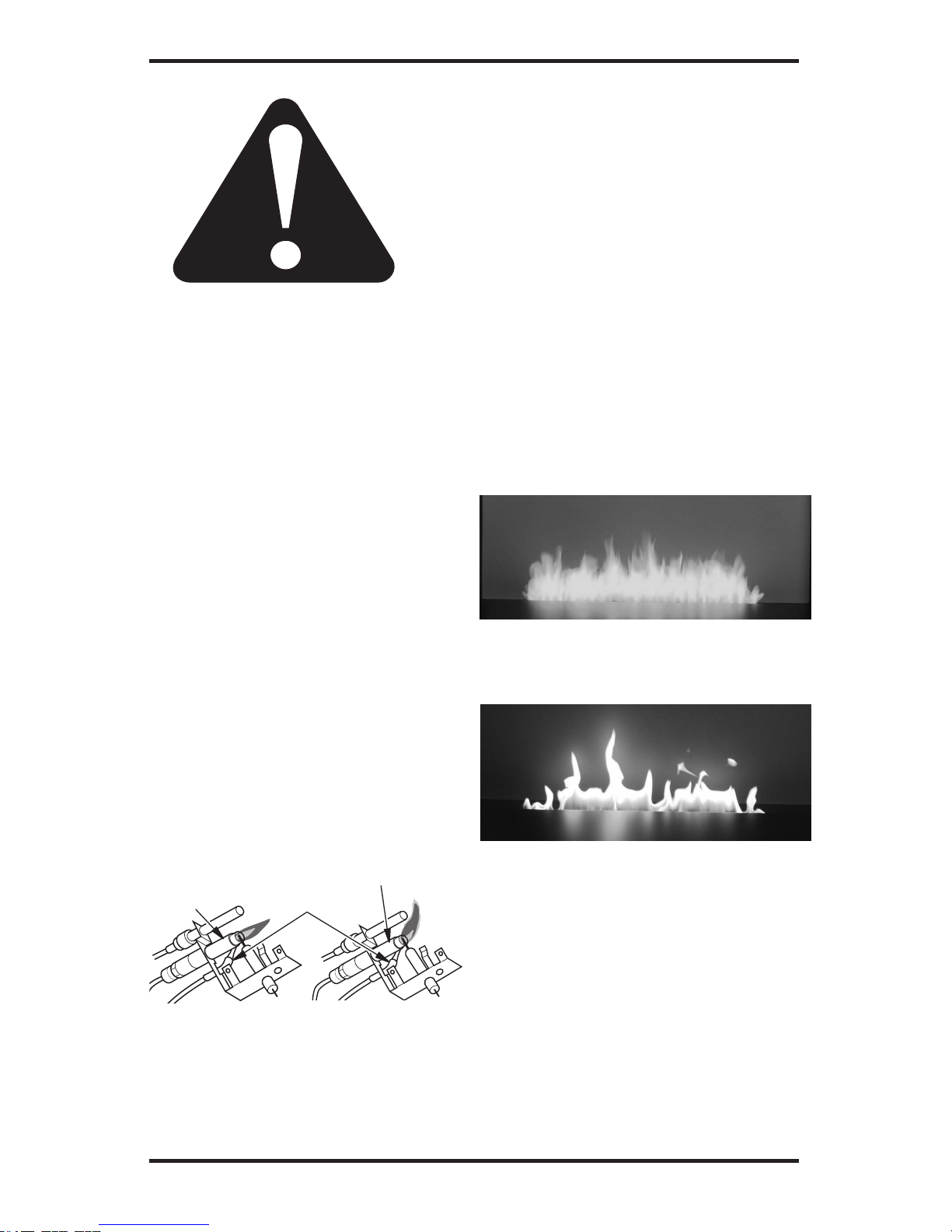
MAIN BURNER
Periodically inspect all burner flame holes with the
heater running.
Some burner flame holes may become blocked
by debris or rust, with no flame present. If so, turn
off heater and let cool. Remove blockage. Blocked
burner flame holes may create soot.
FRONT BURNER FLAME PATTERN
Figure 14 shows correct burner flame pattern with
patern with yellow flame tips and blue base. Figure
15 shows incorrect flame pattern. The incorrect bur-
ner flame pattern shows lazy orange flame.
If burner flame pattern is incorrect, as shown in
Figure 15:
• turn fireplace off (see To Turn Off Gas to Ap-
p
liance).
• see Troubleshooting, page 22.
Figure 12 - Correct
Pilot Flame Pattern
Pilot Burner
Figure 13 - Incorrect
Pilot Flame Pattern
Pilot
Burner
Thermocouple
(Pilot May Vary From Ones Shown)
Figure 14 - Correct Burner Flame Pattern
Figure 15 - Incorrect Burner Flame
Pattern

20
CLEANING AND
MAINTENANCE
WARNING: Turn off fireplace
and let cool before cleaning.
CAUTION: You must keep
control areas, burner and circulating air passageways of
fireplace clean. Inspect these
areas of fireplace before each
use. Have fireplace inspected
yearly by a qualified service
person. Fireplace may need
more frequent cleaning due to
excessive lint from carpeting,
bedding material, pet hair, etc.
WARNING: Failure to keep
the primary air opening of the
burner clean may result in soot-
ing and property damage.
BURNER INJECTOR HOLDER AND
PILOT AIR INLET HOLE
The primary air inlet holes allow the proper amount
of air to mix with the gas. This provides a clean
burning flame. Keep these holes clear of dust, dirt,
lint and pet hair. Clean these air inlet holes prior to
each heating season. Blocked air holes will create
soot. We recommend that you clean the unit every
three months during operation and have heater
inspected yearly by a qualified service person.
We also recommend that you keep the burner
tube and pilot assembly clean and free of dust and
dirt. To clean these parts we recommend using
compressed air no greater than 30 PSI. Your local
computer store, hardware store or home center
may carry compressed air in a can. You can use a
vacuum cleaner in the blow position. If using compr
essed air in a can, please follow the directions on
the can. If you donʼt follow directions on the can,
you could damage the pilot assembly.
1. Shut off the unit, including the pilot. Allow
the unit to cool for at least thirty minutes.
2. I
nspect burner, pilot and primary air inlet
holes on injector holder for dust and dirt (see
Figure 16).
3. Blow air through the ports and holes in the
burner.
4. Check the injector holder located at the end
of the burner tube again. Remove any large
particles of dust, dirt, lint or pet hair with a
soft cloth or vacuum cleaner nozzle.
5. Blow air into the primary air holes on the
injector holder.
6. In case any large clumps of dust have now been
pushed into the burner repeat steps 3 and 4.
Clean the pilot assembly also. A yellow tip on the
pilot flame indicates dust and dirt in the pilot assembly
.
There is a small pilot air inlet hole about
two inches from where the pilot flame comes out
of the pilot assembly (see Figure 17). With the unit
off, lightly blow air through the air inlet hole. You
may blow through a drinking straw if compressed
air is not available.
Figure 16 - Injector Holder On Outlet
Burner Tube
Figure 17 - Pilot Inlet Air Hole
Burner
Tube
Pilot
Assembly
Pilot Air
Inlet Hole
Ports
________
Ports
________
Burner
Tube
________
Injector Holder
________
Primary
Air Inlet
Holes
________
Orifice

21
L100001 29
WIRING DIAGRAM
Note: For proper operation of optional accessories,
the wires from the thermopile to the control must
be connected exactly as shown.
Thermopile
SPECIFICATIONS
Model FR-N
Btu (V ariable) 23 - 34,000
Type Gas Natural Gas
Ignition Piezo
Pressure Manifold 3.0" W .C.
Inlet Gas Pressure (in. of water)
Maximum 10.5"
Minimum* 5"
Shipping Weight 120 lbs.
* For input adjustment
Model FR-P
Btu (V ariable) 24 - 34,000
Type Gas Propane/LP
Ignition Piezo
Pressure Manifold 10.0" W .C.
Inlet Gas Pressure (in. of water)
Maximum 13"
Minimum* 11"
Shipping Weight 120 lbs.
* For input adjustment
DANGER!
PILOT HI
ON
OFF
LO
THE WALL SWITCH OR WALL THERMOSTAT MUST BE CONNECTED
NEVER
TO ANY EXTERNAL POWER SUCH AS HOUSEHOLD 110V CIRCUIT!
OPTIONALREMOTE,
WALLSWITCH OR
TH/TP
THERMOSTAT
TH
TP
ON
OFF

22
POSSIBLE CAUSE
1. Ignitor electrode not connected to ignitor cable
2. Ignitor cable pinched or wet
3. Broken ignitor cable
4. Bad piezo ignitor
5. Ignitor electrode broken
6. Ignitor electrode positioned
wrong
1. Gas supply turned off or equipment shutoff valve closed
2. Control knob not in PILOT
position
3. Control knob not pressed in
while in PILOT position
4. Air in gas lines whe n installed
5. Depleted gas supply (propane/
LP only)
6. ODS/pilot is clogged
7. Gas regulator setting is not
correct
REMEDY
1. Reconnect ignitor cable
2. Free ignitor cable if pinched
by any metal or tubing. Keep
ignitor cable dry
3. Replace ignitor cable
4. Replace piezo ignitor
5. Replace pilot assembly
6. Replace pilot assembly
1. Turn on gas supply or open
equipment shutoff valve
2. Turn control knob to PILOT
position
3. Press in control knob while in
PILOT position
4. Continue holding down control knob. Repeat igniting operation until air is removed
5. Contact local propane/LP gas
company
6. Clean ODS/pilot (see Clean-
ing and Maintenance, page
19) or replace ODS/pilot as-
sembly
7. Replace gas regulator
OBSERVED PROBLEM
When ignitor button is pressed,
there is no spark at ODS/pilot
When ignitor button is pressed,
there is spark at ODS/pilot but
no ignition
TROUBLESHOOTING
WARNING: Turn off heater and let cool before servicing. Only a
qualified service person should service and repair heater.
CAUTION: Never use a wire, needle or similar object to clean
ODS/pilot. This can damage ODS/pilot unit.
Note: All troubleshooting items are listed in order of operation.

23
TROUBLESHOOTING
Continued
POSSIBLE CAUSE
1.
Control knob not fully pressed in
2. Control knob not pressed in
long enough
3. Equipment shutoff valve not
fully open
4. Pilot flame not touching thermocouple, which allows thermocouple to cool, causing
pilot flame to go out. This
problem could be caused by
one or both of the following:
A) Low gas pressure
B) Dirty or partially clogged
ODS/pilot
5. Thermocouple conn ection
loose at control valve
6. Thermocouple damaged
7. Control valve damaged
8. Safety interlock system has
been triggered
1. Inlet gas pressure is too low
2. Burner orifice clogged
3. Thermopile leads disconnected or improperly connected
4. Burner will not come on in
remote position
5.
Wire disconnected from gas control
1. Manifold pressure is too low
2. Burner orifice clogged
1. Burner orifice is clogged or
damaged
2. Damaged burner
3. Gas regulator defective
REMEDY
1. Press in control knob fully
2. After ODS/pilot lights, keep
control knob pressed in 30
seconds
3. Fully open equipment shutoff
valve
4. A) Contact local natural or
propane/LP gas company
B) Clean ODS / pilot (see
Cleaning and Maintenance,
5. Hand tighten until snug, then
tighten 1/4 turn more
6. Replace pilot assembly
7. Replace control valve
8. Wait one minute for safety interlock system to reset. Repeat
ignition operation.
1. Contact local natural or propane/LP gas company
or replace burner orifice
3. Reconnect leads (see Wiring
1. Contact local natural or propane/LP gas company
replace burner orifice
or replace burner orifice
2. Replace damaged burner
3. Replace gas regulator
OBSERVED PROBLEM
ODS/pilot lights but flame
goes out when control knob is
released
Burner does not light after
ODS/pilot is lit
Delayed ignition of burner
Burner backfiring during combustion
page 20) or replace ODS/pilot
assembly
2. Clean burner (see Cleaning and
Maintenance, page
20 )
Diagram, page 2
1)
4. Replace battery in transmitter
and receiver
5. See Wiring Diagram, page 21
2. Clean burner (see Cleaning
and Maintenance, page
20) or
1. Clean burner (see Cleaning
and Maintenance, page 20)

24
POSSIBLE CAUSE
1. Not enough air
2. Gas regulator defective
3. Residues from manufacturing
processes
1. Not enough combustion/ventilation air
1. Turning control knob to HI
position when burners are
cold
2. Air in gas line
3. Air passageways on heater
blocked
4. Dirty or partially clogged
burner orifice
1. When heated, vapors from
furniture polish, wax, carpet
cleaners, etc. may turn into
white powder residue
1. Battery is not installed. Battery power is low
1. Metal expanding while heating
or contracting while cooling
REMEDY
1. Check burner for dirt and
debris. If found, clean burner
(see Cleaning and Mainte-
hours of operation
1. Refer to Air for Combustion
and Ventilation requirements
(page 6)
1. Tur n contr ol knob to LO
position and let warm up for
a minute
2. Operate burners until air is
removed from line. Have gas
line checked by local natural
or propane/LP gas company
3. Observe minimum installation
clearances (see page 9)
or replace burner orifice
1. Turn heater off when using
furniture polish, wax, carpet
cleaners or similar products
1. Replace batteries in
receiver and remote control
1.
This is common with most heaters. If noise is excessive, contact
qualified service person
OBSERVED PROBLEM
Slight smoke or odor during
initial operation
Moisture/condensation noticed
on windows
Heater produces a whistling
noise when burners are lit
White powder residue forming
within burner box or on adjacent
walls or furniture
Remote does not func
tion
Fireplace produces a clicking/
ticking noise just after burner
is lit or shut off
TROUBLESHOOTING
Continued
4. Clean burners (see Cleaning
and Maint enanc e , page
20)
nance, page
20)
2. Replace gas control
3. Problem will stop after a few

25
POSSIBLE CAUSE
1.
Heater burning vapors from
paint, hair spray, glues, cleaners,
chemicals, new carpet, etc. (See
IMPORTANT statement above)
2. Low fuel supply (propane/LP
only)
3. G a s leak. See Warni n g
statement at top of page
1. Not enough fresh air is available
2. Low line pressure
3. O D S / p i l ot is p ar t i a lly
clogged
1. G a s leak. See Warni n g
statement at top of page
2. Control valve or gas control
defective
1. Foreign matter between control valve and burner
2. G a s leak. See Warni n g
statement at top of page
REMEDY
1. Open window to ventilate
room. Stop using odor causing products while heater is
running
2. Refill supply tank (propane/LP
only)
3. Locate and correct all leaks
(see Checking Gas Connec-
tions, page 16)
1. Open window and/or door for
ventilation
2. Contact local natural or propane/LP gas company
3. Clean ODS/pilot (see Cleaning
and Maintenance, page 19)
1. Locate and correct all leaks
(see Checking Gas Connec-
tions, page 16)
2. Replace control valve or gas
control
1. Take apart gas tubing and
remove foreign matter
2. Locate and correct all leaks
(see Checking Gas Connec-
tions, page 16)
OBSERVED PROBLEM
Fireplace produces unwanted
odors
Fireplace shuts off in use (ODS
operates)
Gas odor even when control
knob is in OFF position
Gas odor during combustion
TROUBLESHOOTING
Continued
WARNING: If you smell gas
• Shut off gas supply.
• Do not try to light any appliance.
•
Do not touch any electrical switch; do not use any phone in your building.
• Immediately call your gas supplier from a neighbor’s phone.
Follow the gas supplier’s instructions.
• If you cannot reach your gas supplier, call the fire department.
IMPORTANT: Operating fireplace where impurities in air exist may create odors. Cleaning supplies,
paint, paint remover, cigarette smoke, cements and glues, new carpet or textiles, etc., create fumes. These
fumes may mix with combustion air and create odors. These odors will disappear over time.

26
ILLUSTRATED PARTS BREAKDOWN
( For reference numbers see page 27 )
1
2
3
4
5
6
7
8
9
10
11
12
13
15
16
17
18
19
20

27
PARTS LIST
This list contains replaceable parts used in your firebox.
KEY PART NUMBER
NO. FR-N FR-P DESCRIPTION QTY.
1 H100075 H100074 BURNER 1
2 F200011 F200012 ORIFICE 1
3 F200061 F200061 BURNER CONNECTOR 1
4
C100090 C100091 MAIN GAS VALVE 1
5 C100085 C100086 PILOT ASSEMBLY 1
6 F200062 F200062 PILOT TUBE 1
7 F100015 F100015 PILOT BRACKET 1
8 F200063 F200063 3/8"NPS X 1/4" COMP. 1
9 F200064 F200064 3/8"NPS X 3/8" FLARE 1
10 F200065 F200065 FLEX. CONNECTOR 1
11 F200066 F200066 SHUTOFF VALVE 1
12 F100016 F100016 VALVE BRACKET "L" 1
13 F100017 F100017 VALVE BRACKET "R" 1
14 F100014 F100014 ACCESS PANEL 1
15 C100012 C100012 BATTERY IGNITOR 1
16 C100013 C100013 IGNITOR WIRE HARN. 1
17 F200067 F200067 3/8" X 3" BRASS NIPPLE 1
18 F200110 F200111 PRESSURE REGULATOR 1
19 F100018 F100018 VALVE SHIELD 1
20 RCB-R RCB-R REMOTE RECEIVER 1
22 (OPTIONAL)
23
24
25
ACCESSORIES AVAILABLE (NOT SHOWN)
RCB RCB REMOTE ON/OFF
RCV RCV REMOTE VARIABLE
*
14
TO CHANGE THE BURNER VISIBILITY AT THE REAR
REDUCE NUMBER OF NUTS ON THE SUPPORT BOLTS UNDER BOTH SIDES
OF ACCESS PANEL (AS SHOWN BELOW)

LIMITED LIFETIME WARRANTY
The following components are warranted for life to the original owner, subject to proof of purchase: Firebox,
Combustion Chamber, and Steel Burner.
BASIC WARRANTY
Spark Modern Fires warrants the components and materials in your gas appliance to be free from manufacturing
and material defects for a period of two years from date of installation. After installation, if any of the components manufactured by Spark Modern Fires in the appliance are found to be defective in materials or workmanship, Spark Modern Fires will, at its option, replace or repair the defective components at no charge to the original owner. Spark Modern Fires will also pay for reaonable labor costincurred in replacing or repairing such components for a period of two years from date of installation. Any products presented for warranty repair must be
accompanied by a dated proof of purchase.
This Limited Lifetime Warranty will be void if the appliance is not installed by a qualified installer in accordance with installation instructions. The Limited Lifetime Warranty will also be void if the appliance is not ope-
rated and maintained according to the operating instructions supplied with the appliance, and does not extend to (1)
firebox/burner assembly damaged by accident, neglet, misuse, abuse, alterations, negligence of others, including the installation thereof by unqualified installers, (2) the costs of removal, reinstallation or transportation of
defective parts on the appliance, or (3) indentical or consequential damage. All service work must be performed
by an authorized service representative.
This warranty is expressly in lieu of other warranties, express or implied, including the warranty of merchantability of fitness for purpose and of all other obligations or liabilities. Spark Modern Fires does not assume for it
any other obligations or liabilities in connection with sale or use of the appliance. It states that do not allow limitations on how long an implied warranty lasts, or do not allow exclusion of indirect damage, those limitations of
exclusions may not apply to you. You may also have additional right not covered in the Limited Lifetime War-
ranty. Spark Modern Fires reserves the right to investigate any and all the claims against this Warranty and de-
cide upon method of settlement. For information about this warranty contact:
Spark Modern Fires
53 Chestnut Woods Rd.
Redding, CT 06896
U.S.A.
WARRANTY INFORMATION
KEEP THIS FOR WARRANTY
Model
Serial No.
Date Purchased
Always specify model and serial numbers when communicating with the factory.
Rev.5 03/2013
 Loading...