

Page 1
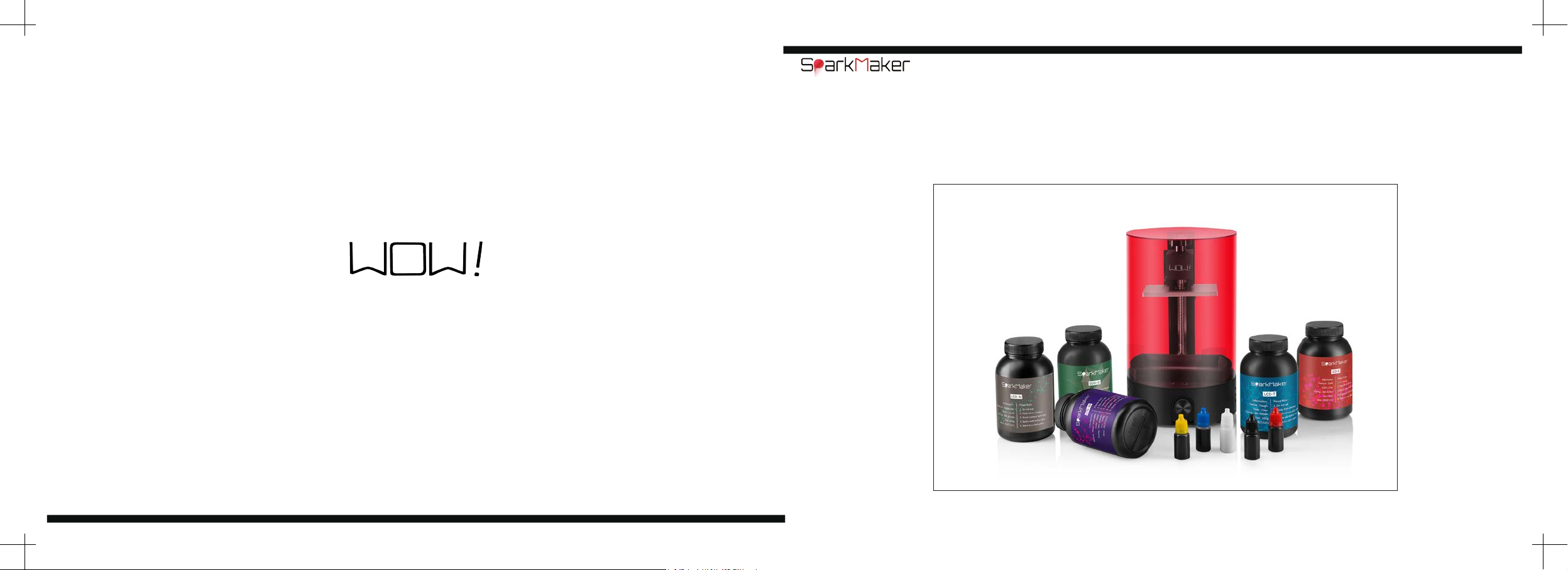
Copyright © 2018 WOW Innovation(ShenZhen) Teth Co.Ltd Copyright
Operating Guide
Please read this entire guide before beginning
Page 2

Page 3
Always with the basic defensive measures when using the printer to reduce the
risk of injury such as fire and electric shock, including the following measures
•Read all instructions before using the printer.
•Do not submerge or expose printer components to water or cleaning solutions.
•To prevent electric shock,do not put the device,power adapter,or plug into water or other liquids.
Important safety notice
•Do not place or store the unit where it can be easily dropped or easily pulled into the tub or basin.
•The printer shouldn't be used outdoors,for indoor use only.
•When removing the plug from the electrical outlet,do not pull on the power adapter.
•When pulling out the plug,grasp the plug,not the power cord.
•Do not use non-vendor original accessories or accessories,they may cause re,electric shoc,injury.
•Do not operate the device if the device power adapter or plug fails or is damaged.
•Do not directly touch liquid resin and the printed model of residual liquid resin on surface. Some people
may be allergic to the resin and have different degrees of allergic reactions. At this time,wash with
soapy water and seek medical advice promptly.
This SLA 3D printer,its photosensitive resin material,printed resin model and packaging materials are
•
not toys. Please keep away from children and pets to avoid suffocation,re,serious allergies,etc. caused
by ingestion.
•Do not use this product for any other purpose.This product is only suitable for SLA 3D printing,and all
equipment parts are only used for UV light curing 3D printing. This device may not be used to create
models that violate local laws and any illegal modications. Unintended use of this product may result in
violation of local laws.
:
Precautions for using the printer
•Do not eat the resin used for printing and the printed model.
•Keep the resin out of reach of children and pets.
•Try to avoid contact between the resin and the skin. Wear gloves when operating.
•Shake the resin evenly before use.
•The resin should be stored in a cool,backlit place.
•When the resin is accidentally splashed on the eyes or skin,it should be washed with soapy water in
time. If you feel unwell,please consult a doctor promptly.
•The printer should be placed in a place where there is no direct sunlight.
•The UV cover should be covered when printing.
•Avoid looking directly at the UV lamp,and if need please wear goggles.
•Do not spill resin on the working panel.
•Children under the age of 18 should be operated under the supervision of an adult.
•Use printers in strict compliance with local laws and regulations.
•Do not disassemble the printer while it is powered on to avoid danger,and disassembling the printer
without permission will void the warranty.
Please keep your instruction manual in a safe place
:
Important safety notice
2
3
Page 4
©This is a desktop-grade SLA light-cured 3D printer that delivers high-quality,SLA 3D printer experience
when the power supply is working properly and components are not damaged.
©Read the entire user manual and become familiar with the features of the product before proceeding.
Failure to operate this product properly may result in serious injury to yourself or others,or damage to the
Disclaimer and warning
product or property damage. This product is a little complex and requires a period of familiarity before it
can be used safely and requires some expertise to operate. Without a strong sense of safety,improper
practices can result in product damage and property damage,and can even cause serious harm to others.
This product is not suitable for children. Do not use parts that are not provided or recommended by
WOW
and must be installed and used in strict accordance with wow guidelines. This guidance document
,
contains instructions for safety, operation,and maintenance. Be sure to visit the
(
https://www.sparkmaker3d.com/
) to download the user manual and read all instructions and warnings
SparkMaker
in the documentation before use.
website
©Please read this document carefully before using the product to understand your legal
rights,responsibilities and safety instructions; otherwise it may cause property damage,safety accidents
and personal safety hazards. By using this product,you are deemed to have understood,endorsed and
accepted all the terms and contents of this document. The user is committed to being responsible for his
or her actions and all consequences arising therefrom. The user undertakes to use the product only for
legitimate purposes and agrees to all terms and content of this document and any relevant policies or
guidelines that may be customized by WOW Innovations (Shenzhen) Technology Co., Ltd.
©WOW Innovation (Shenzhen) Technology Co., Ltd. reserves the right to update this Disclaimer and
Warning. WOW Innovation (Shenzhen) Technology Co., Ltd. does not assume any loss caused by the
user not using the product in this User Manual. In compliance with laws and regulations,WOW Innovation
(Shenzhen) Technology Co., Ltd. has the nal right to interpret this document. WOW Innovation (Shenzhen)
Technology Co., Ltd. reserves the right to update,change or terminate these Terms without prior notice.
Disclaimer and warning
4
5
Page 5
8
Component
End printing
36
Cotton
10
11
12
13
15
17
18
23
24
25
27
31
Check after unpacking
Product working principle
Specifications of SparkMaker
Specifications of SparkMaker FHD
Resin
Color paste
Important definition
Check before printing
Quick start guide
Power connection
Leveling the printing platform
Start printing
Adjustment of the printer
Recycling of resin & Tank cleaning
Replace the FEP lm
Replace the LCD screen
Replace the light board
Adjustment of the Z axis
Filtration residue
Add support
FAQ
Basic operational concept
Terms & Conditions
Customer service
43
44
49
55
68
78
88
91
100
110
113
114
Cotton
6
7
Page 6
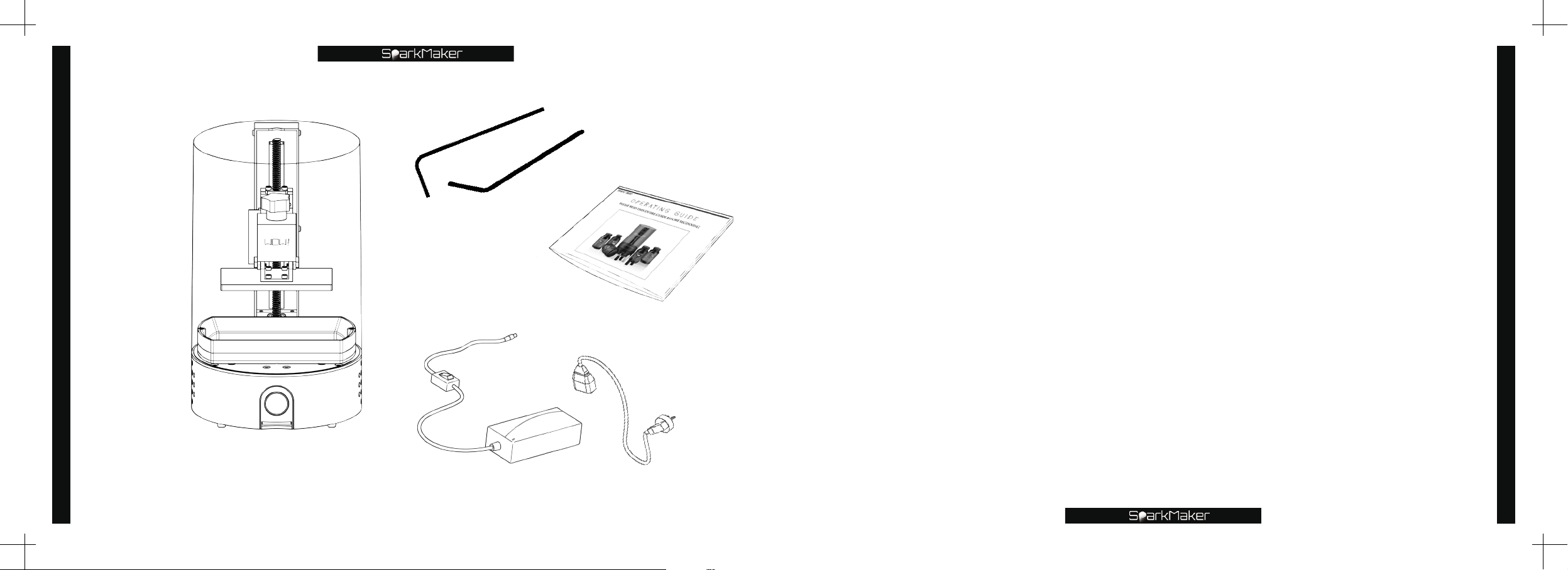
Component
Component
Small hex wrench
Big hex wrench
Operation guide
Please take the time to familiarize yourself with the
items in the package. You should receive the illustrated
component.
To make your products safer to use,WOW provides users with detailed operating
instructions.
Users are advised to check the documentation and components according to the
component list. If you nd any missing or item is not perfect,please contact WOW or
the merchant who sold the product. Please read this document carefully,watch the
instructional video,use the quick start guide to understand the use method,before
printing.
The user manual must be read carefully. Please be sure that you are familiar with the
functions of the various components of this product before using this product.
And learn the basics about 3D printing. If you have any questions about using this
product,please contact a WOW or WOW authorized dealer.
Component
SparkMaker3D printer
Power adapter
8
Power cable
9
Page 7

Check after unpacking
Open the package to confirm that the components are integrity, then
check the printer's functions to ensure that it works properly.
Test power function:
❶
Check after unpacking
10
the indicator of the knob is working properly ,and the indicator of the knob will display the Light blue
lightlight if it working properly .
Test knob function and Z-axis motion:
❷
printing platform move up and down,and whether the knob rotates smoothly.
Test photoelectric switch:
❸
to control the lifting cantilever to descend until the trigger piece on the lifting cantilever is inserted into
the photoelectric switch groove to trigger it to conrm whether the lifting cantilever stops.
Test print function:
❹
SparkMaker
website www.sparkmaker3d.comand save it to the SD card. Insert the SD card with the print le into
the printer card slot and the indicator of the knob will become the green breathing light,then press
the knob to start printing. At this time,the indicator light changes from green to red and flashes,the
lifting cantilever will drop to the position of the trigger photoelectric switch,then the light board will,emit
ultraviolet light,the fan will start to work,the screen will display the bottom layer pattern,and wait for a
bottom exposure time. After that,the light board is extinguished,the lifting cantilever will rise a certain
distance,and then decline again,then the light board emit ultraviolet light,and the screen displays the
next pattern... Continue this process until the end of printing.
Test tank:
❺
holes. Pour some water into the tank to check if it will leak.
Connect the power supply. After the printer is powered on,confirm that if
Rotate the knob to confirm whether it can control the
Remove the printing platform and continue to rotate the knob clockwise
Remove the printing platform,download the print file
versionor
Check if the FEP membrane at the bottom of the tank has obvious scratches or broken
"print.fhd"
SparkMaker FHD
for
versionfrom
"print.wow"
SparkMaker
for
official
Product working principle
SparkMaker SLA 3D printer
Designing a 3D solid model through 3D software,slice the model with
generated data will be used to accurately control the switch of the light board and the
movement of the lifting platform through the main board. The light beam emitted by the light
board passes through the controllable liquid crystal screen and is irradiated onto the surface
of the liquid photosensitive resin according to the designed path. Curing a layer of resin in a
specic area of the surface. When this layer is processed,a section of the model is generated.
The lifting platform is raised by a certain distance,the solid layer is covered with another layer
of liquid resin,and then the second layer is scanned,and the second solidified layer is firmly
bonded to the previous solidified layer,so that the layers are superposed to form a threedimensional model. After the model is taken out of the resin,clean the resin on the surface
of the model with alcohol,and the nal curing,and then polished,painted or colored to get the
desired product.
SparkStudio
the
,
Product working principle
11
Page 8
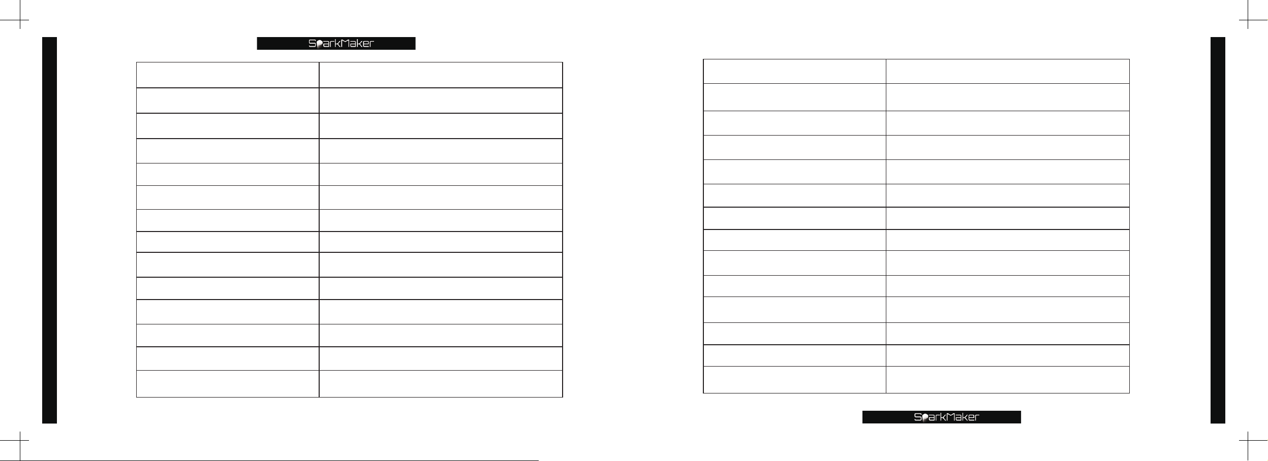
Specification of the
Specification of the
XY-axis direction accuracy
Specication of the SparkMaker
SparkMaker
Z-axis direction accuracy
Single layer printing time
Molding size
Print material
Printing method
Print le format
Printer control
Curing ultraviolet light
Operating software
Stepper motor drive
Physical dimension
Total weight
98mm*55mm*125mm
100μm
25-100μm
Photosensitive resin
8-15 S
SD card offline printing
*.wow
Knob
400-410nm 24W UV LED
SparkStudio
128 microsteps
Φ
170mm*284mm
2.2KG
XY-axis direction accuracy
Z-axis direction accuracy
Single layer printing time
Molding size
Print material
Printing method
Print le format
Printer control
Curing ultraviolet light
Operating software
Stepper motor drive
Physical dimension
Total weight
110mm*61.8mm*125mm
100μm
25-100μm
Photosensitive resin
3-12 S
SD card offline printing
*.fhd
Knob&APP
400-405nm 84W UV LED
SparkStudio
128 microsteps
Φ
170mm*288mm
2.2KG
SparkMaker FHD
Specication of the SparkMaker FHD
12
Input power
DC 24V 2A 48W
Input power
DC 24V 4A 96W
13
Page 9
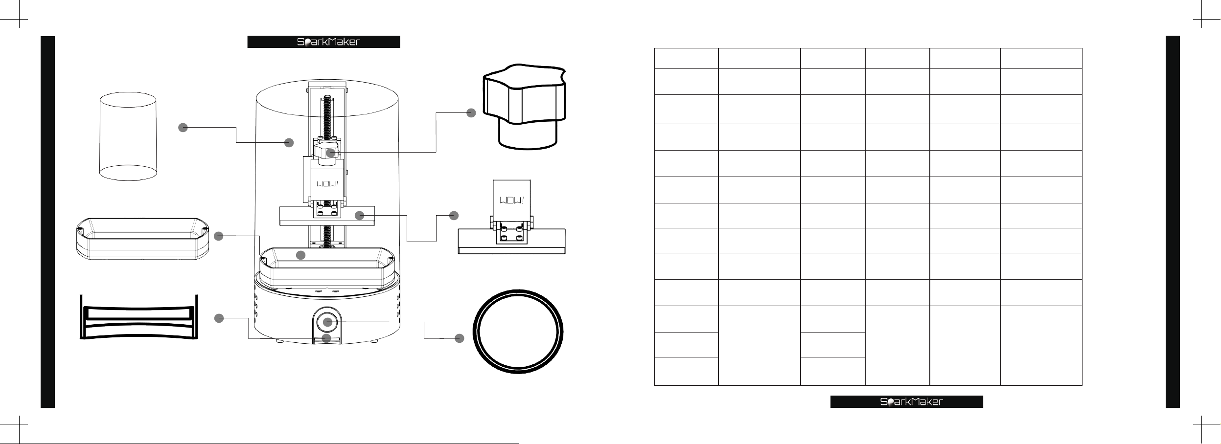
Type Feature Color Hardness Elongation Description
LCD-T Tough Clear 60D 115% ABS Alike
LCD-W
Specication of the SparkMaker
Water
Washable
Clear 60A 150%
Water
Washable
Resin
LCD-C Casting Clear 80A 24% Casting
Platform handle
Cover
LCD-E Elastic Clear 26A 300% Rubber Alike
LCD-N Nylon Alike Black 75D 115% Nylon Alike
Resin
LCD-H High HDT Clear 90D 3% >300℃HDT
LCD-G Super Clear Clear 70D 5% Super Clear
Resin tank
Printing platform
LCD-Q easy dyeing light yellow 80D 5% colorful paste
LCD-MG Rigid&Tough gray 80D 5% Rigid&Tough
Card slot
LCD-BG
LCD-BW White
Hard
Gray
75D 3% Rigid
LCD-BF Flesh
14
Knob
15
Page 10
Resin
16
Precautions for resin use:
Theoretically,resins with a curing band of
❶
other third-party resins are used,the printed parameters must be adjusted by yourself.
SparkMaker
❷
bottom
need to be adjusted by users.
❸
❹
increased appropriately after adding the color paste.
❺
precipitating.
❻
printing parameters change greatly
❼
resin on such plastics.
❽
printer.
❾
❿
photosensitive resins should be used.
⓫
different degrees of deformation during printing.
and the curing band is on
,
Damage to parts caused by the use of third-party resins will invalidate the warranty.
The color paste addition ratio should be less than
The resin after adding the color paste should be evenly mixed to prevent the color paste from
Do not mix a variety of different types of resins,and it will cause the resin properties and
The photosensitive resin will react with some plastics such as
Use of third-party color paste or other dyes may result in printing failure or damage to the
Should choose the right resin according to different needs.
For models with small features and high precision requirements,deep color and high hardness
If photosensitive resin with low hardness,high toughness and softness,which may have
s resin can also be used on other
'
355-420nm
,
making it difcult to print.
400-410 nm
SLA 3D printer use PTFE lm or FEP lm as tank
SLA 3D printer,but the actual printing parameters
1%
can be used in
and the resin exposure time should be
,
ABS,P
SparkMaker
C,etc. Do not drop the
but if
,
Color principle
CMYK is the four-color printing mode used for color printing.
Based on the principle of trichromatic mixing,with black ink,a total of four colors are
mixed and superimposed to form a "full-color printing".
The four standard colors are
C=Cyan M=Magenta Y=Yellow K=key
Here K refers to the Key,it can also represent Black,because printing is more often
used in black. In addition,we also added a white color paste.
:
:
C+M=Purple
M+Y=Orange
C+Y=Green
,
Method of operation
Pour the resin into a cup rst
:
paste to the cup,stir evenly,nally pour the resin of the mixed color paste into
the trough and print.
Notice:
Adding a white color paste will make the color soft.
Adding black paste will make the color dignied.
Users can adjust different doses and ratios to call up richer colors.
The color paste addition ratio should be less than
should be appropriately increased after adding the color paste.
The resin after adding the color paste should be stirred evenly to prevent the color
paste from being precipitated.
1%
then add a drop of color
and the resin exposure time
,
Color paste
Color paste
17
Page 11
Important Definition
Cover:
Notice:
❶
❷
Tank:
Important Definition
FEP film:
cure resin.
Notice:
❶
❷
❸
damage to the LCD screen.
❹
❺
overow damage to the LCD screen.
Printing platform:
Plate:
Notice:
❶
❷
❸
❹
Platform handle:
18
Notice:
Protective cover to prevent external light and dust from affecting the resin in the tank.
Do not drop the resin on the cover. If it is accidentally dropped on it please clean it in time.
Do not put heavy objects on the cover to avoid crushing the cover.
The container for storing resin during printing.
Located at the bottom of the tank for release demolding during printing,UV light can pass through it to
The FEP lm at the bottom of the tank is easily damaged. Do not scratch it with a sharp object.
After removing the tank,use a paper towel pad on the bottom of the tank to avoid damage to the FEP lm.
Please clean the resin that has accidentally dropped on the outer wall of the tank and the screw hole to avoid
When installing the tank,please make sure that the FEP lm is close to the LCD screen to avoid affecting print.
Less than
Aluminum alloy plate for sticking the model on the printing platform.
Make sure the print platform is fully inserted under the platform handle.
Make sure the print platform is correctly leveled before printing to avoid damage to the LCD screen.
When leveling,please cross lock four screws while pressing down the aluminum plate.
Do not scratch too deep under the aluminum plate,but slight scratches do not affect printing.
240ml
resin should be poured into the tank. Do not pour in too much resin,it will result in resin
Parts for leveling and xing aluminum plate.
Fix the platform on the Z axis to prevent it from moving.
Tighten the platform handle before printing to prevent it from sliding during printing.
❶
Please clean the resin residue on the handle of the platform in time.
❷
Knob: Knob operation and indicator light:
1.
Control motor:
platform descends; when it rotates counterclockwise,the platform rises.
2.
Printing:
indicator light turns into red and ashing,and the printer enters the printing state.
3.
Stop:
terminate printing.
4.
Pause:
platform will lift
5.
Continue:
descend and continue printing,and the indicator light will turn red and ashing.
If there is no print le in the SD card or the SD card is not recognized,after pressing the knob,it will change from
6.
green to red and quickly turn to green again.
Notice:
Do not drop the resin on the knob.If it drops accidentally,please clean it in time.
❶
Do not over-tighten the two screws above the knob.
❷
SD card:
In printing mode,long press the knob,the indicator will turn blue and eventually turn green,which is to
In printing mode,press the knob and the indicator will turn blue.After the current print layer is cured,the print
The carrier for storing print les.
SD card sort:
Notice:
When inserting,the metal contact point of the SD card is facing up,please do not insert the opposite.
❶
Multiple of print les can be stored in the SD card,but when you use the knob to control the printer to print,the
❷
printer can only recognize the print file named
SparkMaker FHD
file to be printed as
you want to change the print file,you can directly modify the file name. If you use APP to control printing,on the
APP,you can directly select the file you want to print .
In the uninsert SD card state,the indicator light is light blue.When the knob rotates clockwise,the
Insert the SD card,the indicator light will become green breathing light,press the knob to start printing,the
and the printer will pause printing.
30mm
After the printing platform lifted by
Used to read SD card data.
versionand print it. Users can name the files that do not print as other names,and name the
for
"print.wow"
SparkMaker
(
and pause printing,press the knob,the printing platform will
30mm
"print.wow"
version)or
for
SparkMaker
"print.fhd"
for
versionor
SparkMaker FHD
"print.fhd"
for
version
if
,
Important Definition
19
Page 12

Please use
❸
Adapter:
DC socket:
adapter.
Notice:
Do not use a non-original power adapter to avoid danger.
❶
Please plug in the print DC socket before powering on the adapter. Do not plug in the DC socket after the
❷
adapter is powered.
Important Definition
Light board:
Notice:
Do not look directly at the UV light emitting from the light board. Wear goggles if do it.
❶
Please ensure that the fan works normally when the light board is working to avoid damage to the
❷
machine caused by excessive temperature.
Used to convert
Shading tape:
LCD screen:
resin.
Notice:
The LCD screen is extremely fragile,please be careful.
❶
If the tank leaks out and causes the resin to ow out and cured on the LCD screen,please carefully remove the
❷
cured resin residue before the next printing.
Make sure that there are no resin residues on the LCD screen to block UV light.
❸
If the print failed,please clean the residual resin in the tank and aluminum plate in time to avoid crushing the
❹
LCD screen when printing next time.
Make sure the printing platform is properly leveled when printing,so as to avoid damage to the LCD screen.
❺
Please ensure that the FEP lm is close to the LCD screen to avoid affecting the print quality.
❻
Make sure that the black tape completely block the unrequired UV light around the LCD screen.
20
❼
Screw motor:
SDHC (Secure Digital High Capacity)
110V-240V AC to 24V DC
Located at the right rear of the printer,is the power socket to connect the printer and the
Provide UV light to cure the liquid resin in the tank.
Used to block the unrequired UV light around the LCD screen.
Used to display the section pattern of the printed model and cooperate with the UV light to cure the
Used to drive the lifting cantilever move up and down
with a maximum capacity lower than
to provide power to the printer.
.
32GB
.
Copper nut:
Guide rail:
lifting cantilever:
Notice:
Do not block the rotation of the screw motor.
❶
Do not over-tighten the mounting screws of the copper nut.
❷
Do not drop resin and other debris on the guide rail and the screw that interfere with its work.
❸
Please add grease to the screw,copper nut and guide rail in time to avoid excessive abrasion.
❹
Do not drop the resin on the bafe. If it is accidentally dropped,please clean it in time.
❺
Photosensitive resin:
Notice:
Do not touch the skin directly with the resin. Wear gloves when handling. If skin contact occurs,wash
❶
it with soapy water. If you feel unwell,please consult a doctor.
The resin remaining after printing,if it would not be used for a long time,please keep it in cool and dark place.
❷
Shake the resin evenly before use.
❸
Do not eat the printed model and the resin used for printing.
❹
Keep the resin out of reach of children and pets.
❺
Do not drop the resin on any parts other than the tank and aluminum plate.If it is dropped,please clean it in
❻
time.
Use of third-party color paste or other dyes may result in printing failure or damage to the printer.
❼
Working panel:
Hexagonal wrench:
Trigger piece:
Photoelectric switch:
Notice:
Do not block the photoelectric switch,otherwise the photoelectric switch will not be triggered.
❶
For working with screw motors.
For linear motion guidance.
Motor and guide rail control its up and down during printing.
Liquid light curing resin for printer use.
Panel for mounting components such as LCD screens and tank.
Big hex wrench and small hex wrench for hex screws.
Used to trigger photoelectric switch.
Used to determine if the platform has reached the lowest point.
Important Definition
21
Page 13

When leveling,please ensure that the trigger piece is inserted into the photoelectric switch groove.
❷
Do not drop the resin on the working panel and photoelectric switch.
❸
Cooling the control system and the light board.
Fan:
Notice:
Make sure that the cooling fan is working properly and avoid system failure due to excessive temperature.
❶
Please make sure not to block the air outlet and air inlet.
❷
LCD screen FPC cable:
Important Definition
Alcohol:
Note:
Please use alcohol with a concentration higher than
1.
Do not soak the model in alcohol for too long.
2.
Please use alcohol carefully to avoid safety risks.
3.
A cleaning agent used to clean printed models.
UV curing lamp:
Note:
Please use a curing lamp with a band of
1.
When curing the model with curing lamp,the model can be placed in glycerin to prevent the deformation of the
2.
model due to temperature and other factors in the curing process.
Too long post-curing time will lead to shrinkage and yellowing of the model,and too short post-curing time will
3.
lead to the incomplete curing model of the model is soft.
22
Connecting the mainboard to the LCD screen.
.
95%
used to solidify the newly printed model so that it is completely solidied.
395-420nm
and a power of more than
10W
.
Check before printing
Keep the power connection stable.
❶
Knob rotates smoothly and presses smoothly.
❷
Z-axis movement is smooth and unobstructed.
❸
There is no resin residue on the aluminum plate of the printing platform.
❹
The handle on the print platform has been tightened.
❺
The print platform has been correctly leveled.
❻
The tank is installed correctly,and the FEP lm at the bottom of the tank is close to the LCD screen.
❼
No resin residue in the tank and on the FEP lm.
❽
No residual resin on the outer wall of the tank,the bottom of the tank,the LCD screen and the working
❾
panel.
The resin poured into the tank is less than
❿
240ml
the printing process.
Printed model files have no fault and are not damaged.
⓫
Ensure the model's the position of the long-span cantileve,the lowest point of the layer and the position
⓬
that needs to be strengthened,add with the right size of support and the right amount of support,and the
right bottom valve.
The slice parameters such as the layer thickness,exposure time,and lifting speed of the print file are set
⓭
correctly.
The slice file is completely saved in the SD card,the bottom surface of the model is completely attached
⓮
to the lowest point of the printer,and there is no fault on the print model file
If you use the knob to control the printer to print,you need to name the print file as
⓯
SparkMaker
The SD card is a
⓰
FAT32
⓱
.
When the card slot is inserted,the SD card metal contact point is inserted face up into the machine card
version)or
"print.fhd"
C10 high-speed
The SD card is completely unlocked by hardware. The metal contacts are intact and free of stains.
SparkMaker FHD
for
card with a capacity lower than
slot and is in fully contact with it.
. If the model is large,the resin can be added during
for
version
"print.wow"
and save it to the SD card.
,
32GB
.
The file system format is
Check before printing
23
Page 14

Quick start guide
Power cord connection
Plug the power cord socket
into the adapter interface
first,and plug the power
cord into the socket.
Plug the adapter plug into the
DC input on the back of the
printer,then press the switch on
the cable to start the printer.
Socket
Power cord
DC input
Adapter
Switch
Power cord socket
Power cord connection
25
Page 15
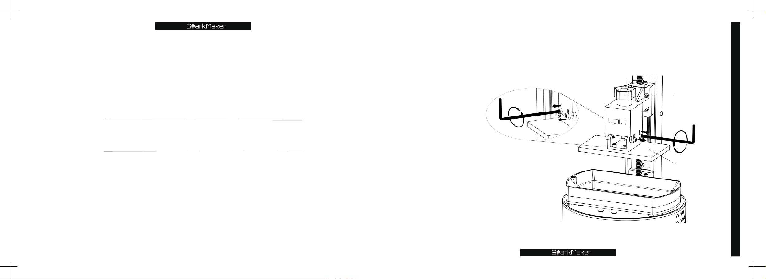
Use the big hex wrench to loosen the four screws on both sides of
the platform counterclockwise so that the aluminum plate can move
up and down freely.
Big hex wrench
Handle
Leveling the printing platform
Leveling the printing platform
*
Notice:
Do not unscrew the screw completely.
❶
Make sure the handle is fully tightened.
❷
Please ensure that there are no residual resin
❸
or obstacle on the aluminum plate and the tank
to affect the leveling.
Make sure the tank is installed correctly.
❹
Big hex wrench
Aluminum plate
27
Page 16
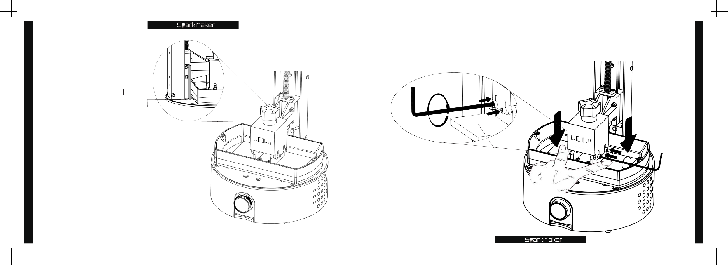
Use two fingers to press down on each side of the aluminum plate,and
press it close to the FEP film,meanwhile use the big hex wrench to tighten
the four screws clockwise to fix the aluminum plate.
Leveling the printing platform
Trigger piece
Photoelectric switch
Rotate the knob clockwise
to lower the platform to the
lowest point of the tank,that the
platform can no longer move
down meanwhile trigger piece
trigger the photoelectric switch.
*
Notice:
When the photoelectric switch is triggered,the
trigger piece should be inserted into the
middle notch.
28
Big hex wrench
*
Notice:
Please stagger tighten the four screws
to make the aluminum plate and the FEP
film close enough,so as to prevent the
aluminum plate from lifting up on one side
and causing the leveling to fail.
Aluminum plate
Leveling the printing platform
Big hex wrench
Hand
29
Page 17
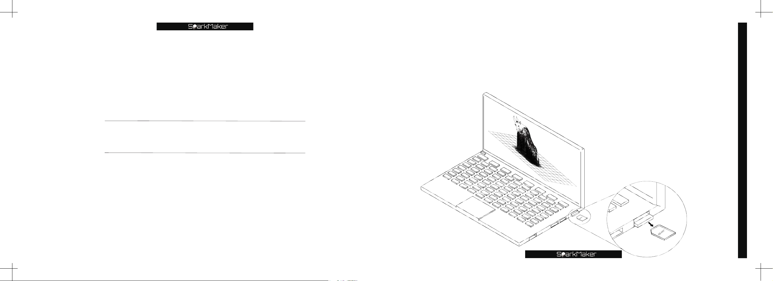
Start printing
Insert the SD card into the computer,open the
software,import the *.stl file of the model into the
SparkStudio
SparkStudio
software,adjust the appropriate angle,add the appropriate support,set
the correct print parameters,save the slice file *.wow(for
version)or *.fhd (for
SparkMaker FHD
version)in the SD card after
SparkMaker
slicing,and then remove the SD card from PC.
*
Notice:
See below for methods and rules for
❶
adding supports and for setting print
parameters.
If you use the knob to control the
❷
printer to print,the print file must be
named as
version)or
FHD
version)
"print.wow"
"print.fhd"
SparkMaker
(for
SparkMaker
(for
Start printing
Computer
SD card
31
Page 18
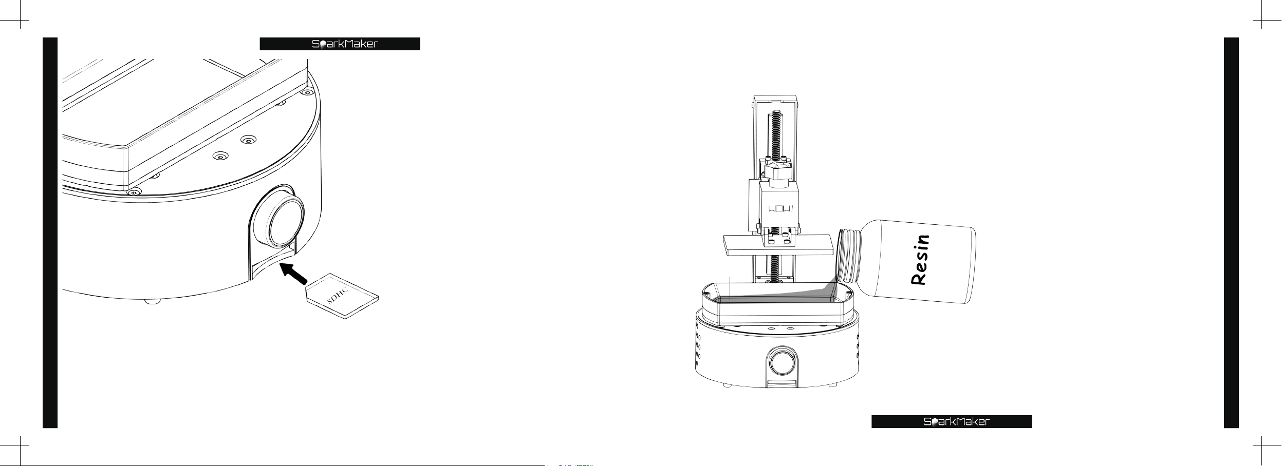
Start printing
32
Card slot
SD card
Insert the SD card into the
card slot under the printer.
*
Notice:
When inserting,the metal contact
point of the SD card is facing
up,please do not insert the opposite
to avoid damage to the card slot.
Open resin bottle and pour the appropriate resin (less than 240ml) into the
tank according to the size of the model.
*
Notice:
Please do not pour in excess
❶
resin to prevent resin from
overflowing,resulting in damage to
the LCD screen.
Please do not drop the resin on
❷
the screw hole of the tank,the outer
wall of the tank and the working
panel,resulting in damage to the
LCD screen. If it accidentally flows
in,please clean it in time.
Resin remaining in the resin
❸
Resin
Resin bottle
bottle,should be sealed in a dark
shade away from children and pets.
If not used for a long time,please
❹
pour the resin into the storage
container. Do not place the resin in
the tank for more than two weeks.
Please ensure that there are no
❺
residual resin or obstacle on the
aluminum plate and the tank to avoid
damage to the LCD screen.
Start printing
33
Page 19
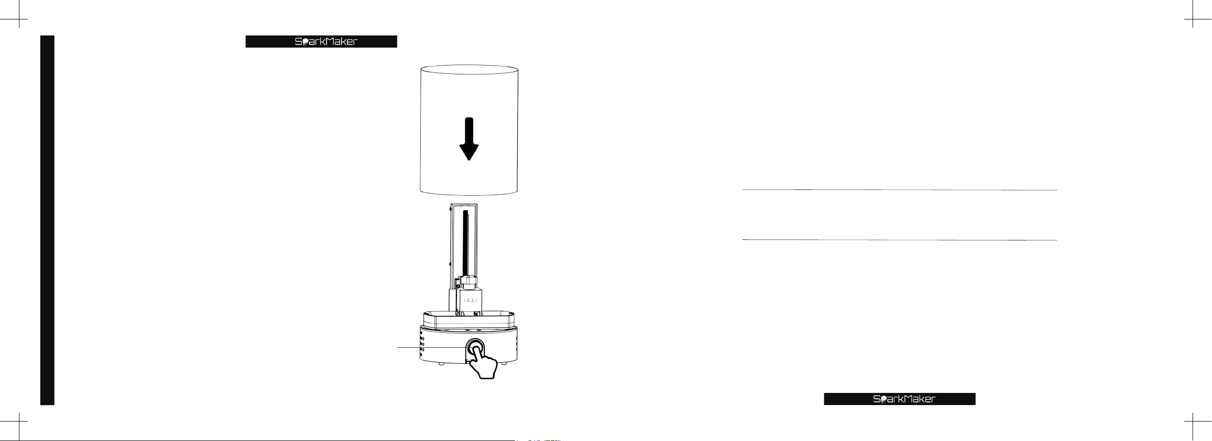
Start printing
(As shown)Cover the printer with the
cover,press the knob,the indicator will
turn red and flashing,and the printer will
start printing.
*
Notice:
Do not place the printer in a location exposed to strong
❶
light,including but not limited to windows,under the table
lamp,and outdoors.
Avoid looking directly at the UV lamp. If you need to
❷
see it,please wear goggles.
Cover
End of printing
Knob
34
Hand
Page 20
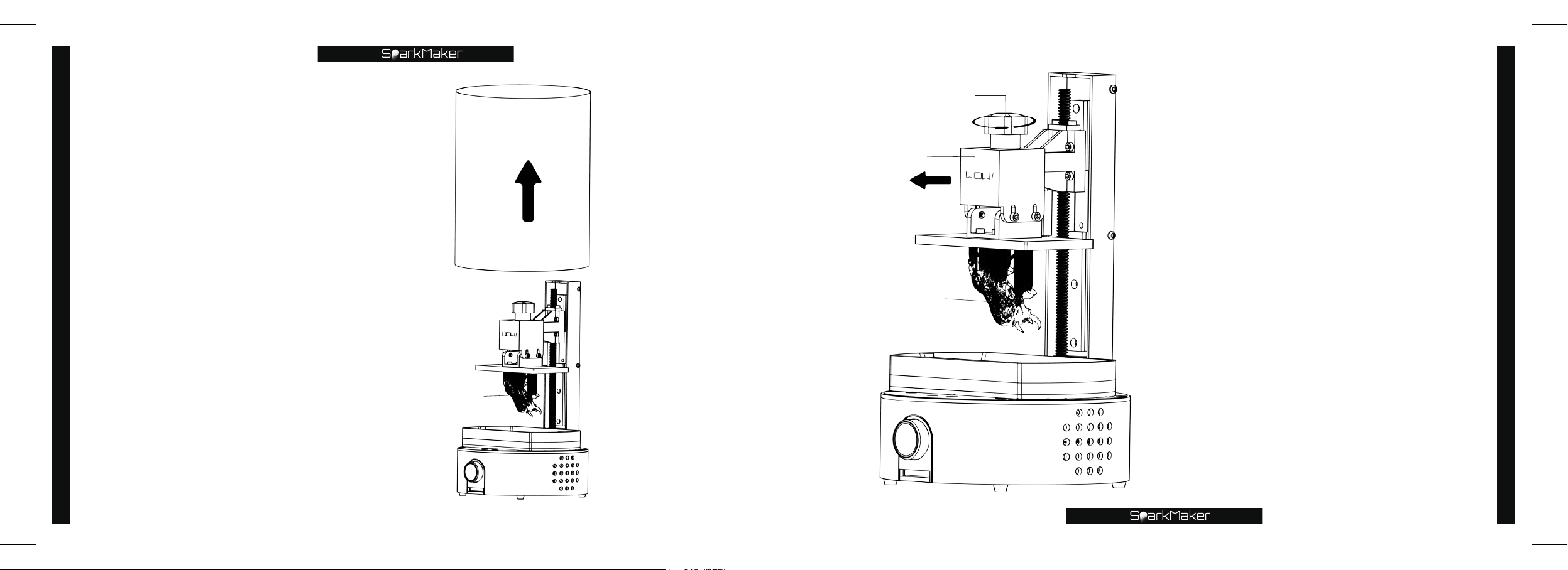
End of printing
The knob indicator
changes from a flashing
red light to a green
breathing light,it means
the end of printing.
Remove the cover from
the printer
Model
Cover
Platform
Model
Handle
After loosening the platform handle
counterclockwise,pull the platform
forward and remove it.
*
Notice:
Do not completely unscrew the handle.
❶
Do not touch the printed model directly to
❷
avoid resin contact with the skin.
When removing the platform,do not
❸
drop the resin on the outer wall of the
tank,the mounting screw holes,the working
panel,the outer casing and the cover,and the
installation clearance.
Be careful to avoid model damage when
❹
removing the platform.
End of printing
36
37
Page 21
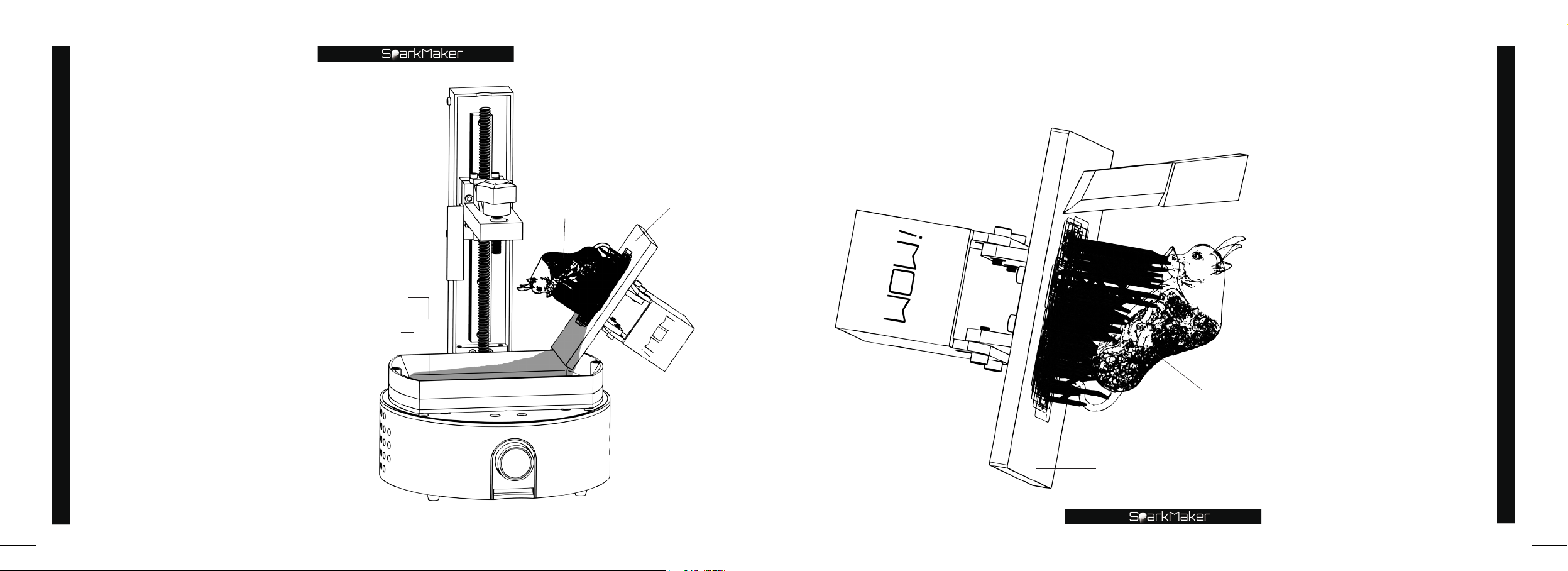
Use a knife or shovel to separate the model from the aluminum plate along
the bottom of the model.
Tilt the platform so that
the resin remaining on
End of printing
the aluminum plate and
the model flows back into
the tank along a corner
of the aluminum plate.
*
Notice:
When tilting the platform,do not
drop the resin on the outer wall
of the tank,the mounting screw
holes,the working panel,the outer
casing and the cover,and the
installation clearance.
38
Resin
Tank
Model
Aluminum plate
Aluminum plate
Knife
Model
*
Notice:
Please use tools and
❶
shovel carefully to avoid
accidental injury.
Please lift up or cut from
❷
the bottom of the model.
Do not leave too deep
scratches on the bottom
of the platform and avoid
damage to the model.
Please clean the
❸
resin residue stick to the
platform.
End of printing
39
Page 22
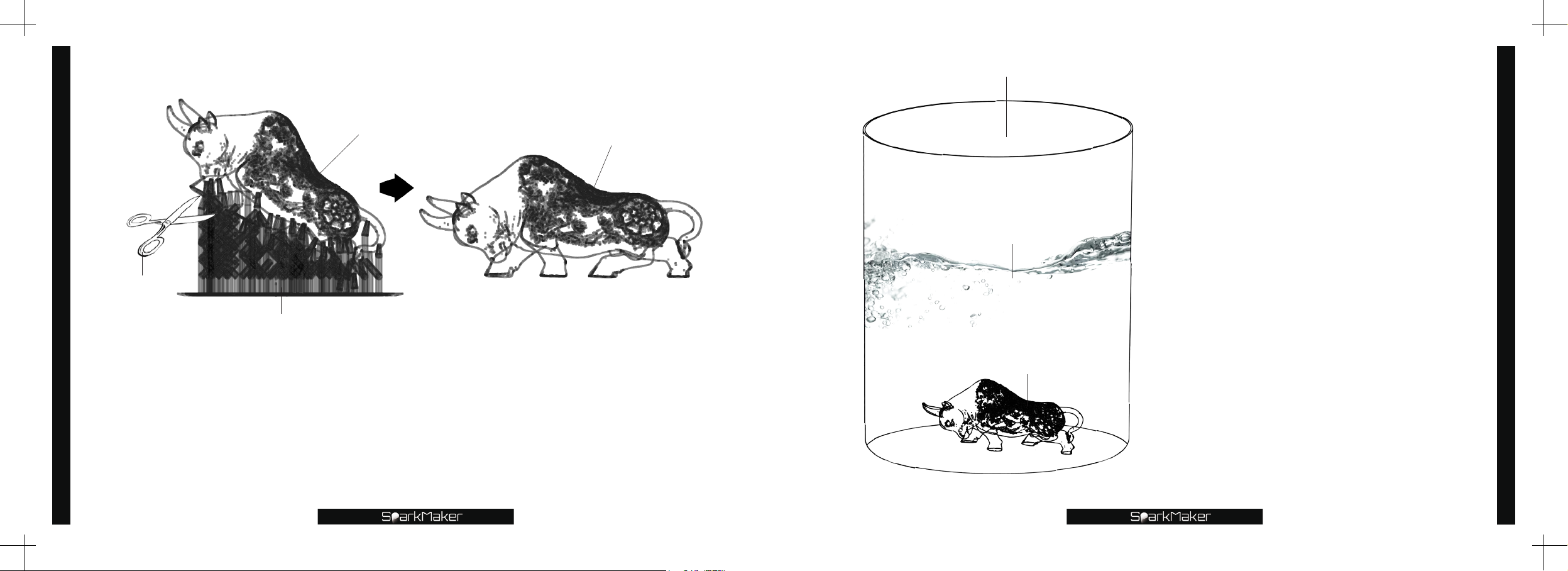
End of printing
Scissors
Carefully cut off the support on the model with tools such as scissors or
cutting pliers.
Notice:
*
Please use tools such as scissors carefully to avoid accidental injury and damage to the model.
❶
The support can be softened by the use of an electric blowing hot wind to soften the support,making
❷
it easier to dismantle.
Support
Model
Model
Cleaning container
Alcohol
Model
Place the trimmed model in
a cleaning container,pour
the appropriate amount of
alcohol that concentration
above 95%
clean it with
,
a soft brush or ultrasonic
vibration for about 60
seconds,clean the uncured
resin on the model surface
,
then take out the model,and
blow dry the model with
cold air.
*
Notice:
You can use a hair dryer to speed up
❶
the evaporation of the model surface
alcohol.
Do not wash for too long,avoid
❷
model damage and peeling.
Please carefully use and store
❸
alcohol to avoid safety issues.
End of printing
40
41
Page 23
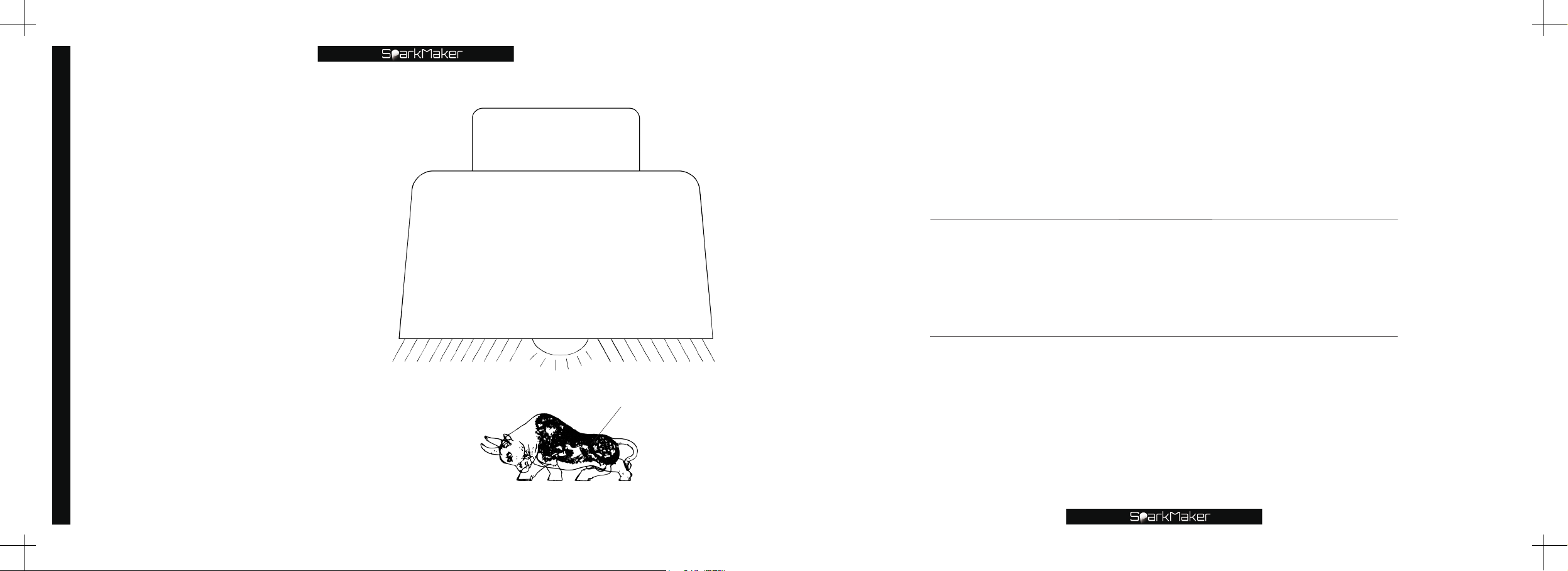
Place the air-dried model
on a UV light or sunlight for
about 10 minutes.
End of printing
*
Notice:
In order to prevent the model
❶
from being deformed by heat during
illumination,the air-dried model can be
completely placed in water or glycerol.
The illumination time can be
❷
adjusted according to the intensity
of the light,so that the model can be
completely cured.
Excessive curing time will cause the
❸
model to shrink and yellow,Insufficient
curing time will result in incomplete
curing of the model,and it will cause the
model to be too soft.
42
UV light
Adjustment of the printer
Recycled resin and tank cleaning
Model
Page 24
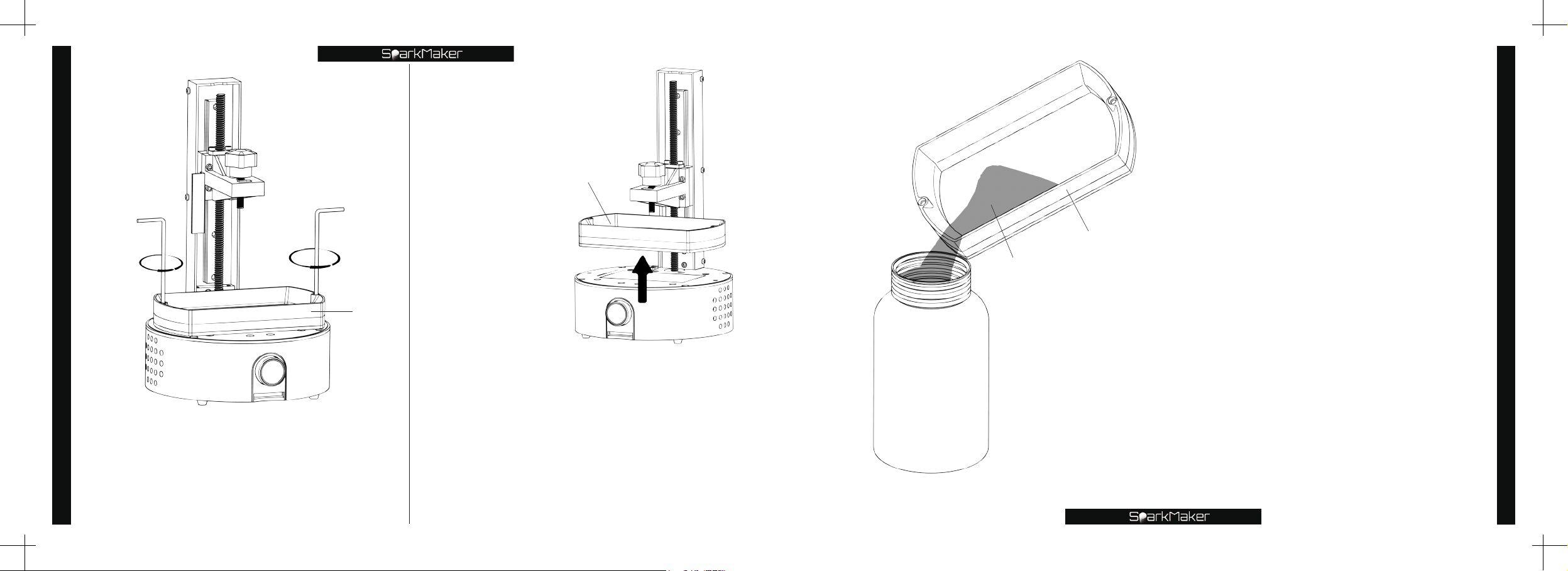
Remove the tank.
Recycled resin and tank cleaning
Big hex wrench
Use the big hex wrench to unscrew
the screws on both sides of the
tank counterclockwise.
*
44
Notice:
Please remove the printing platform first.
Big
hex wrench
Tank
Tank
*
Notice:
Please remove the printing platform first.
❶
When removing the tank,do not drop the resin
❷
on the outer wall of the tank,the mounting screw
holes,the working panel,the outer casing and the
cover,and the installation interspace.
Do not scratch the FEP film at the bottom of the
❸
tank when removing the tank.
Please place the removed tank properly on a
❹
clean and soft surface to avoid damage.
Resin bottle
Resin
Tank
Pour the remaining resin in the
tank into the prepared resin
storage container along a corner
of the tank.
*
Notice:
Please seal the poured resin in a dark
❶
place.
Please clean the resin on the outer wall of
❷
the tank in time to avoid damage to the LCD
screen.
Recycled resin and tank cleaning
45
Page 25
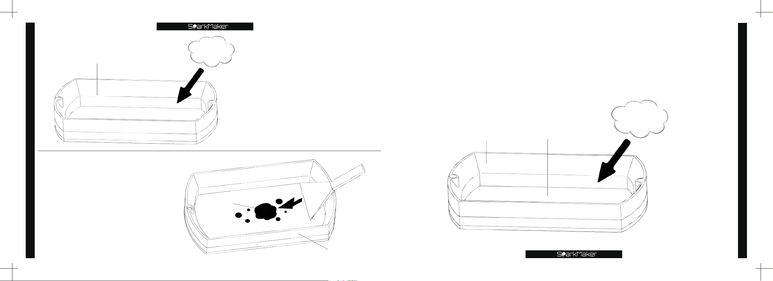
Tank
Recycled resin and tank cleaning
Paper towel
After pouring the resin in the
tank,carefully wipe the resin
remaining in the tank and the
outer wall of the tank with a
paper towel.
Finally,carefully wipe the inside of the tank,the outer wall of the
tank and the upper and lower sides of the FEP membrane with
alcohol wipes
*
Notice:
The standard of thorough cleaning is that the FEP film is completely free of residue and no
resin,and there is no resin residue inside and outside the tank.
.
Alcohol wipe
Recycled resin and tank cleaning
46
Use a plastic shovel to remove
the residual resin stuck on the
FEP film at the bottom of the
tank.
*
Notice:
Please be careful to prevent the bottom of
the tank from being scratched.
Residual resin
Shovel
Tank
Tank
FEP membrane
47
Page 26
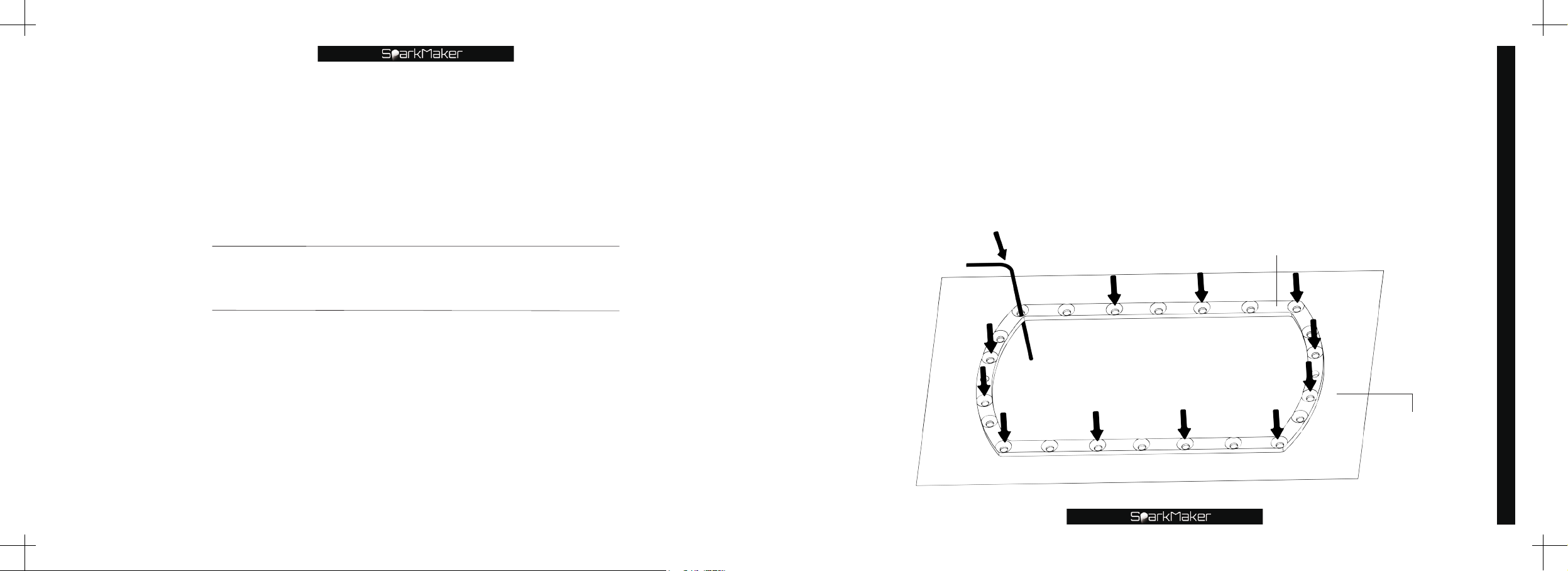
Replace the FEP film
Lay the FEP film under the tank and poke 12 holes in the
position shown with a small hex wrench.
*
Notice:
Make sure that the position of each hole that is poked matches the position of
❶
the hole in the lower layer of the tank.
Do not damage the FEP film.
❷
Clean all tank parts before replacing the new FEP film.
❸
Small hex wrench
Replace the FEP film
Lower layer of the tank
FEP lm
49
Page 27
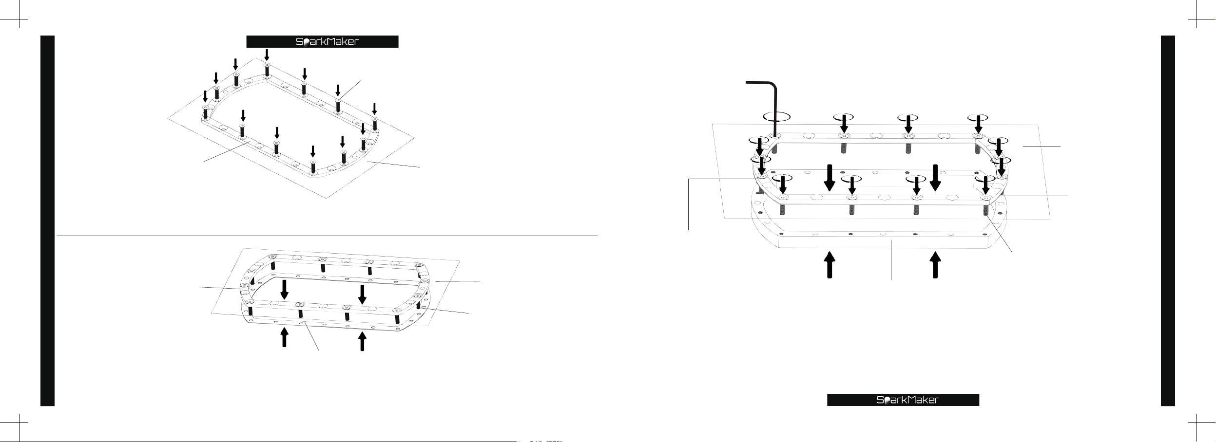
Lower layer of the tank
Replace the FEP film
Insert 12 M3 short screws into the position where the hole was
previously poked.
M3 short screw
FEP lm
Small hex wrench
Lower layer of the tank
M3 short screw
FEP lm
Rubber washer
Replace the FEP film
50
Lower layer of the tank
Align the lower layer of the tank with the rubber washer according
to the screw holes position.
Rubber washer
FEP lm
M3 short screw
Middle layer of the tank
Align the lower layer of the tank and the middle layer of the tank
according to the screw holes. Use a small hex wrench to tighten the
screws clockwise to clamp the FEP film and rubber washer.
51
Page 28
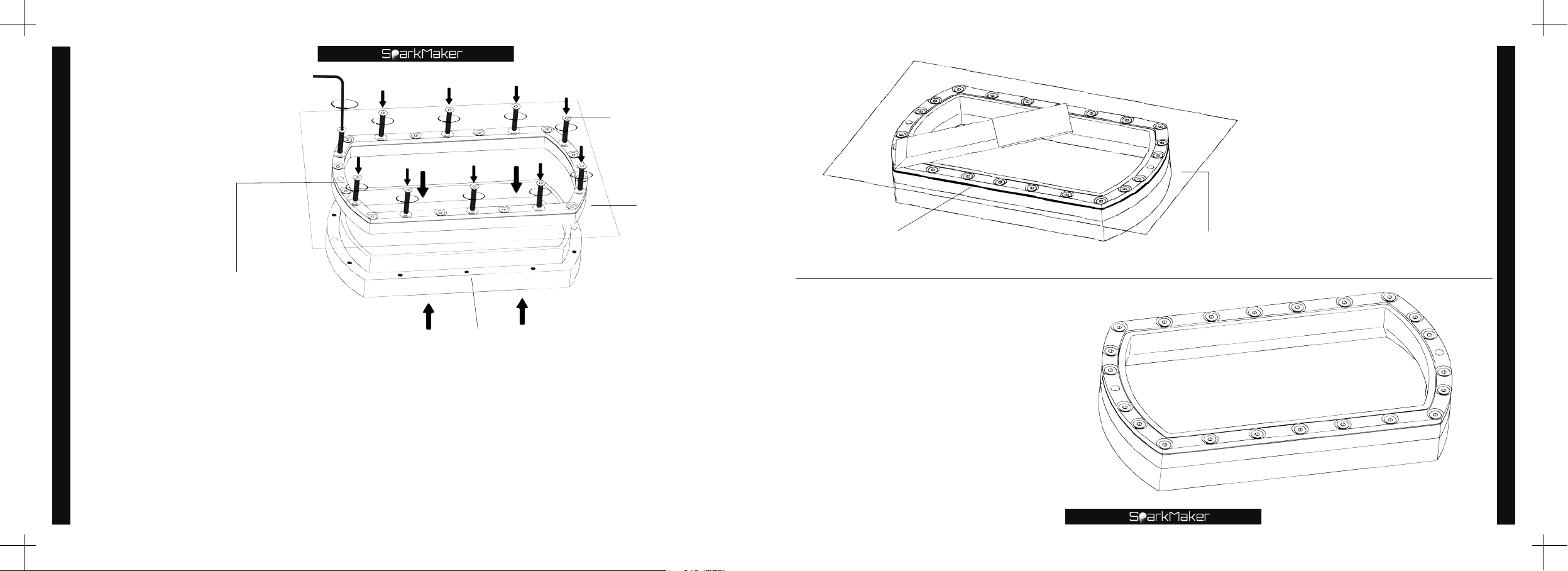
Replace the FEP film
Lower layer of the tank
Small hex wrench
M3 long screw
FEP lm
Outer edge of the tank
knife
FEP lm
Use a knife along the
outer edge of the tank to
remove the excess FEP
film and rubber washer
neatly.
*
Notice:
Please use the knife carefully
❶
to avoid accidental injury.
Do not damage the FEP film in
❷
the tank.
Do not scratch the tank.
❸
Replace the FEP film
52
Upper layer of the tank
Insert 10 M3 long screws into the remaining holes,use a small hex wrench to tighten the
screws clockwise,so that the lower layer of the tank is tightly attached to the upper layer
of the tank,and the rubber washer is pressed to tighten the FEP film.
*
Notice:
Do not overtighten the individual screws so that the other screws cannot be tightened. The screws
❶
should be tightened evenly.
Make sure that the lower and top layer of the tank are tightly pressed so that the FEP film is higher than
❷
the lower plane of the tank,and all the screw heads do not protrude to hinder the tank installation.
Get a new tank.
*
Notice:
Before installing and using,clean the
tank with alcohol wipes to ensure that
there is no obstruction on the FEP film
and no resin residue on the tank.
53
Page 29
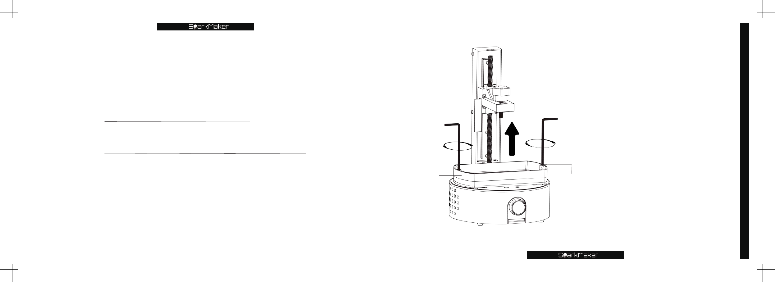
Replace the LCD screen
Big hex wrench
Tank
Big hex wrench
Round head screw
Use the big hex wrench
to unscrew the screw on
both sides of the tank
counterclockwise and
remove the tank upward.
*
Notice:
Please remove the printing
❶
platform first.
When removing the tank,do not
❷
drop the resin on the outer wall
of the tank,the mounting screw
holes,the working panel,the outer
casing and the cover,and the
installation interspace.
Do not scratch the FEP film
❸
at the bottom of the tank when
removing the tank.
Please place the removed
❹
tank properly on a clean and soft
surface to avoid damage.
Replace the LCD screen
55
Page 30
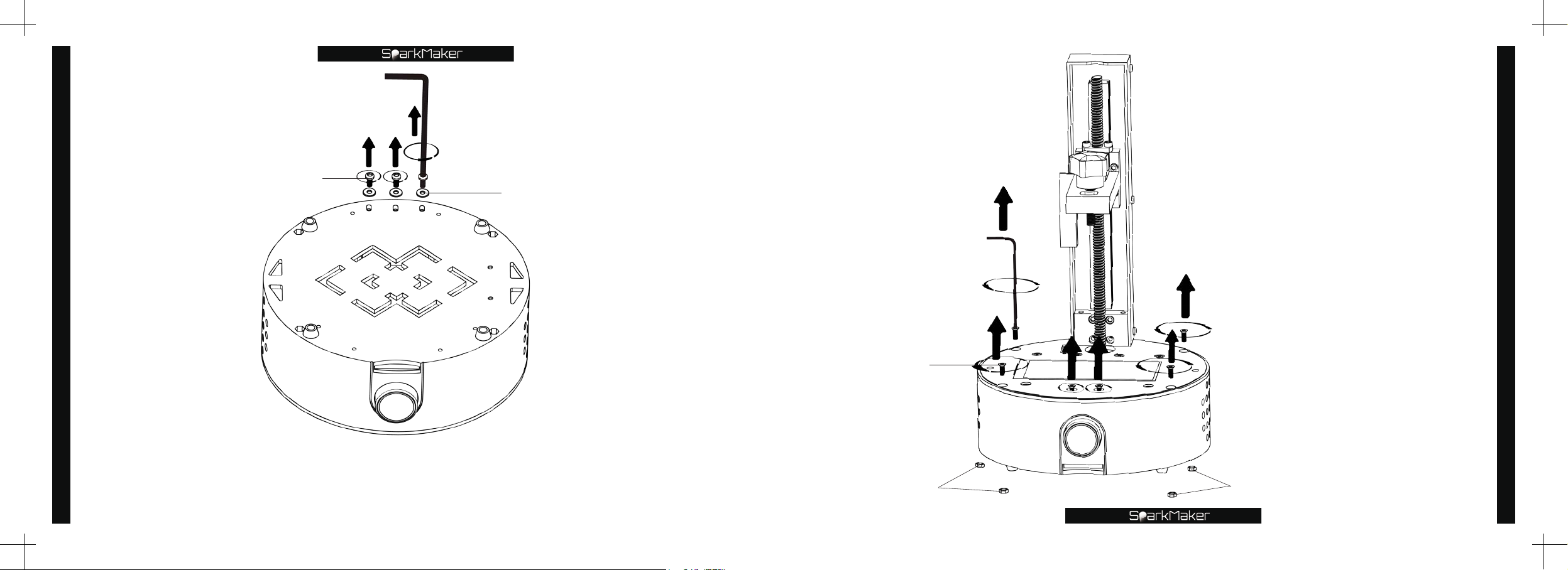
Replace the LCD screen
Round head screw
Big hex wrench
washer
Small hex wrench
Flat head screw
Use the small hex
wrench to turn
counterclockwise to
unscrew the four flat
head screws on the
working panel and the
two flat head screws
above the knob.
*
Notice:
Please take good care of the
❶
removed parts.
Please take care of the four M3
❷
nuts installed in the bottom of the
printer.
Replace the LCD screen
56
Use the big hex wrench to unscrew the three round head screws
and three washers on the bottom of the printer counterclockwise.
*
Notice:
Please take good care of the removed parts.
M3 nut
M3 nut
57
Page 31
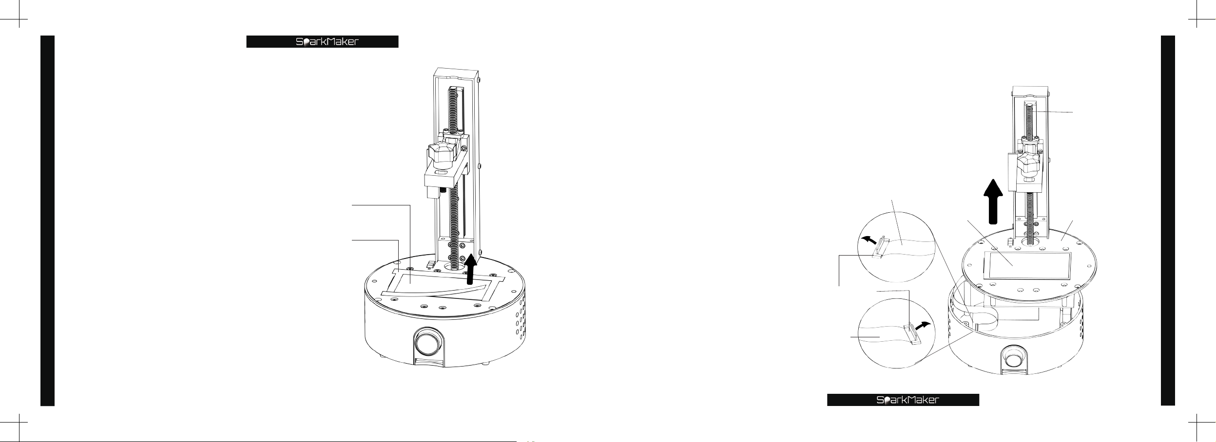
Remove the shading tape
Replace the LCD screen
around the LCD screen.
LCD screen
Shading tape
Slowly pull up the Z axis and
the working panel,and open the
LCD screen interface to release
the LCD screen cable.
*
Notice:
Please carefully pull up
❶
the Z axis,do not pull it too
high and the cable will be
damaged.
Please carefully open the
❷
LCD screen interface,do not
damage the LCD cable and
LCD interface.
LCD screen FPC interface
LCD screen cable
LCD screen cable
SparkMaker
SparkMaker
FHD
LCD screen
Z axis
Replace the LCD screen
Working panel
58
59
Page 32

Extend the cable of the new LCD
screen into the interior along the
left side gap of the working panel
and install the new LCD screen in
the correct position.
Replace the LCD screen
Take out the LCD screen
and pull out the LCD cable
from the gap on the left side
of the working panel.
*
Notice:
Do not damage or stain the
❶
tempered glass behind the LCD screen.
Do not remove the tempered glass
❷
behind the LCD screen.
60
LCD screen
LCD screen cable
LCD screen
LCD screen cable
*
Notice:
Before installing,please remove
❶
the protective film on both sides of the
new LCD.
Do not damage or stain the LCD
❷
screen and the tempered glass behind
the LCD screen during installation.
Replace the LCD screen
61
Page 33
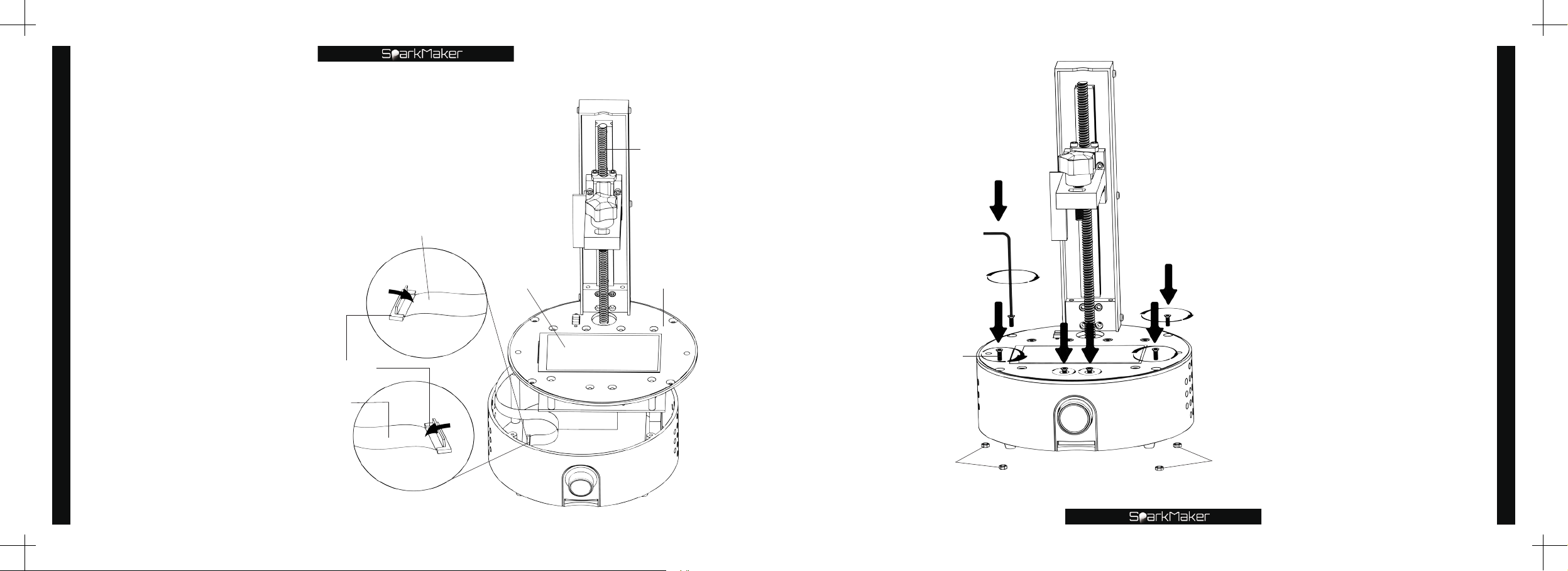
Insert the cable into the
LCD interface and press
the connector down.
Replace the LCD screen
*
Notice:
When installing the LCD cable,the
metal face of the LCD cable is
facing down. When pressing the
interface,please confirm that the
cable is fully connected to the LCD
interface.
LCD screen FPC interface
LCD screen cable
LCD screen cable
SparkMaker
LCD screen
Z axis
Working panel
Small hex wrench
Flat head screw
Slowly lower the Z-axis
and working panel and
close the housing. Plug
the four M3 nuts on the
bottom of the housing
back into the bottom
mounting holes,and then
tighten the six flat head
screws shown.
*
Notice:
Do not damage the LCD screen.
Replace the LCD screen
62
SparkMaker
FHD
M3 nut
M3 nut
63
Page 34
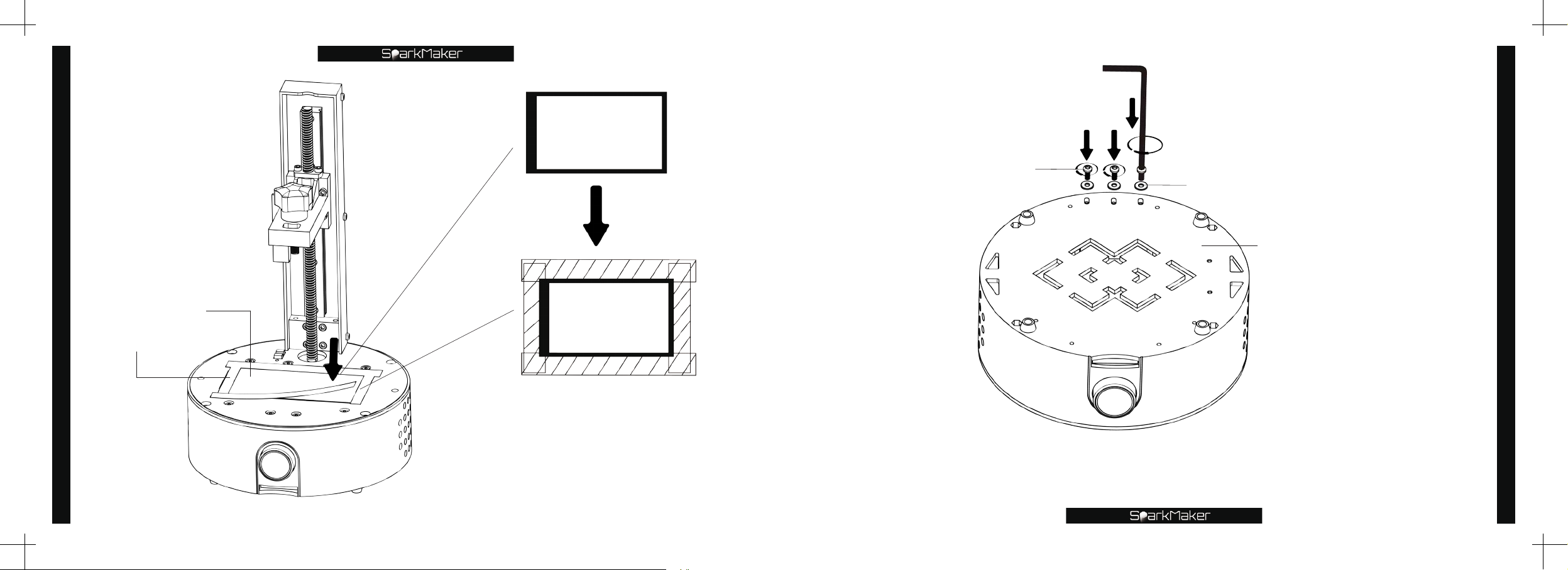
Replace the LCD screen
LCD screen
Shading tape
64
In the state of the printing, the
backlight is lit,and the LCD screen
is displaying pattern,attach
shading tape along the black edge
around the LCD screen as shown.
Big hex wrench
Round head screw
Washer
Bottom of the printer
Tighten the three round head screws and three washers on
the bottom of the printer clockwise with the big hex wrench.
Replace the LCD screen
65
Page 35
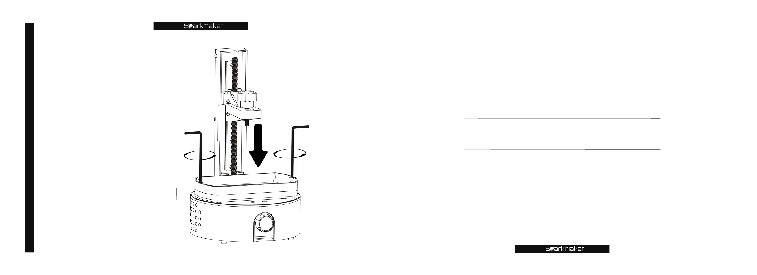
Use the big hex wrench
to tighten the two
Replace the LCD screen
round head screws on
both sides of the tank
clockwise.
*
Notice:
Please ensure that there is no
❶
obstruction on the LCD screen
and in the FEP film in the tank.
Make sure that the tank is
❷
installed in a suitable position. The
FEP film is in close contact with
the LCD screen.
66
Big hex wrench
Big hex wrench
Replace the light board
Round head screw
Tank
Page 36
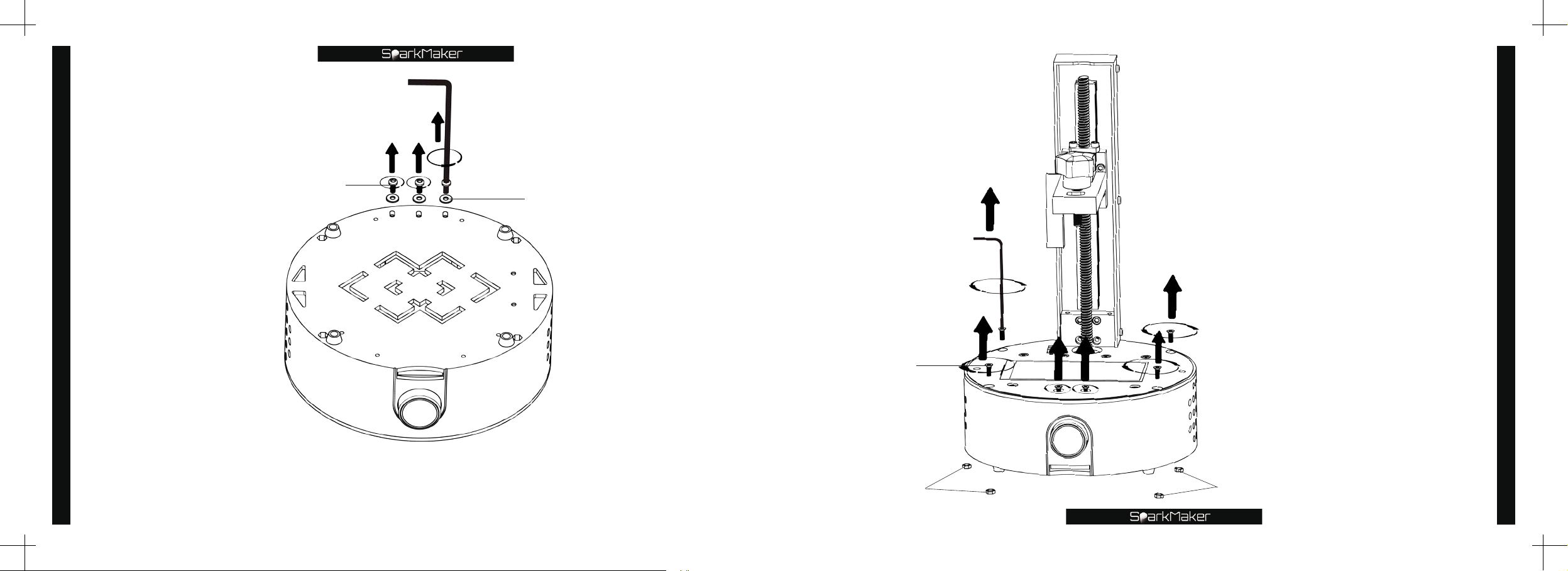
Replace the light board
Big hex wrench
Round head screw
washer
Small hex wrench
Flat head screw
Use the small hex wrench
to turn counterclockwise
to unscrew the four flat
head screws on the
working panel and the two
flat head screws above the
knob.
*
Notice:
Please take good care of the
❶
removed parts.
Please take care of the four M3
❷
nuts installed in the bottom of the
printer.
Replace the light board
68
Use the big hex wrench to unscrew the three round head screws
and three washers on the bottom of the printer counterclockwise.
*
Notice:
Please take good care of the removed parts.
M3 nut
M3 nut
69
Page 37
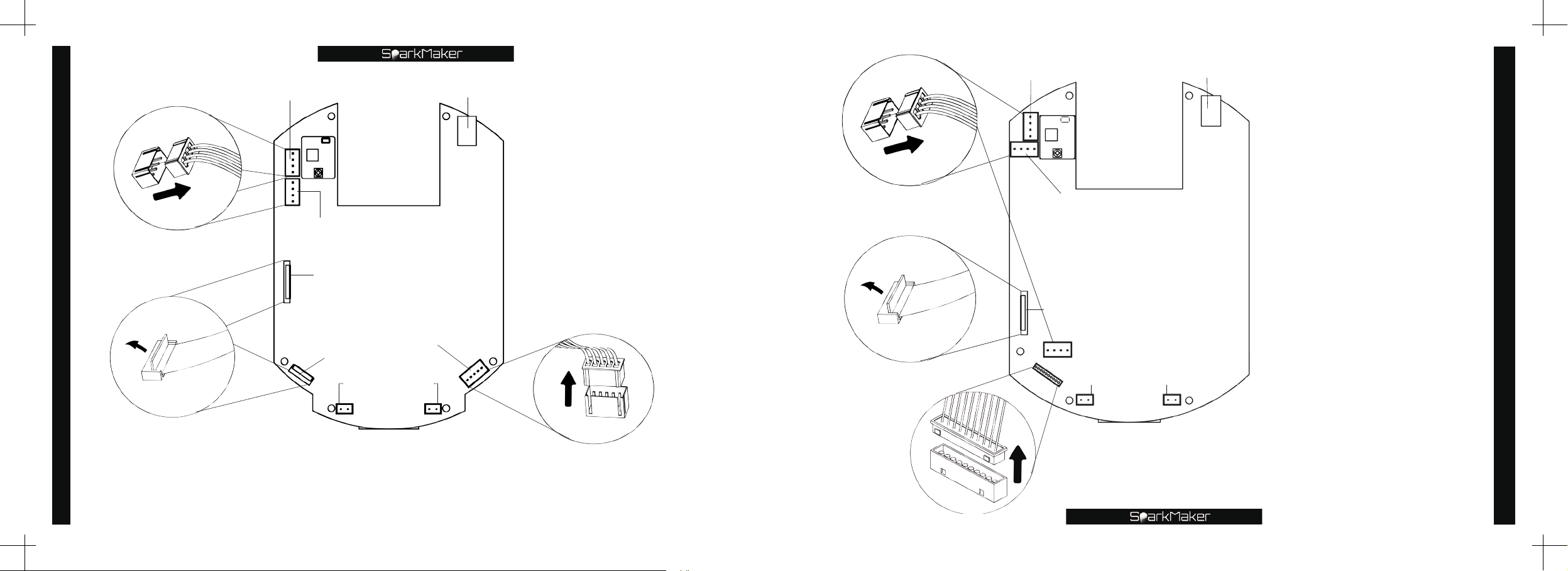
Replace the light board
Four-wire plug
Motor interface
Photoelectric
switch interface
LCD interface
Knob interface
DC input
SparkMarker
Mainboard
Light board interface
(As shown) Slowly pull
up the Z axis and the
working plane,open the
FPC interface upwards
,
release the FPC cable of
the LCD and the knob
,
pull out the four-wire
plug of the photoelectric
switch and screw motor
upwards,and pull out the
five-wire plug of the light
board upwards.
Four-wire plug
Motor interface
Photoelectric
switch interface
SparkMarker FHD
LCD interface
Mainboard
DC input
(As shown) Slowly pull
up the Z axis and the
working plane,open
the FPC interface
to loosen the LCD
screen cable,pull out
the four-wire plug
of the photoelectric
switch,stepper motor
and light board
upwards,and pull out
ten-wire plug of the
knob upwards.
Replace the light board
70
FPC cable
Fan interface
Notice:
*
Please carefully open the FPC
interface and carefully pull out the
plug,do not tear the cable.
Five-wire plug
FPC cable
Fan interface
Ten-wire plug
*
Notice:
Please carefully open the FPC
interface and carefully pull out
the plug,do not tear the cable.
71
Page 38
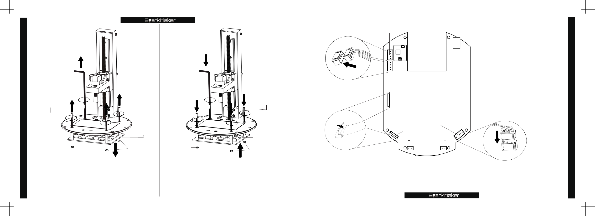
Replace the light board
Small hex wrench
Flat head screw
M3 nut
Light board
M3 nut
Small hex wrench
M3 nut
Flat head screw
Light board
M3 nut
Four-wire plug
FPC cable
Motor interface
Photoelectric
switch interface
LCD interface
Knob interface
DC input
SparkMarker
Mainboard
Light board interface
Fan interface
As shown) Press down
(
on the LCD screen and
the knob FPC cable
,
insert down the fourwire plug of the limit
switch and screw
motor,and insert the
five-hole plug of the
light board down.
Replace the light board
72
Use the small hex wrench to turn
counterclockwise to unscrew the flat
head screws of the four fixed light board
around the LCD screen and remove the
light board from below.
Installation of the new light board, use the
small hex wrench to turn clockwise,and
use the M3 nut at the lower end of the
light board to screw the four flat head
screws around the LCD screen.
*
Notice:
Please carefully open the FPC
interface and carefully pull out the
plug,do not tear the cable.
Five-wire plug
73
Page 39
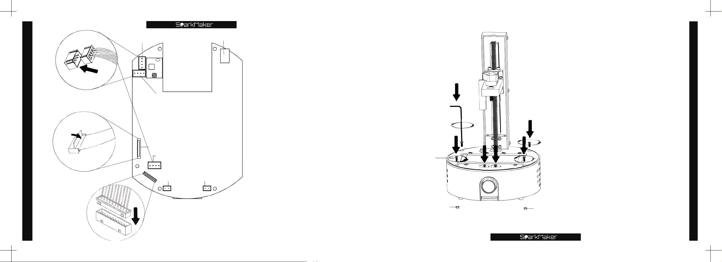
Replace the light board
Four-wire plug
FPC cable
Motor interface
Photoelectric
switch interface
SparkMarker FHD
LCD interface
Mainboard
Light board interface
Fan interface
DC input
(
As shown
) Press
down on the FPC
connector,connect the
LCD cable,and insert
the four-wire plug
of the photoelectric
switch,stepper motor
and light board
downwards,and insert
the ten-wire plug of
the knob downward.
*
Notice:
Please carefully open the
FPC interface and carefully
pull out the plug,do not tear
the cable.
Small hex wrench
Flat head screw
M3 nut
M3 nut
Slowly lower the Z-axis
and working panel and
close the housing. Plug
the four M3 nuts on the
bottom of the housing
back into the bottom
mounting holes,and then
tighten the six flat head
screws shown.
Replace the light board
74
Ten wire plug
75
Page 40
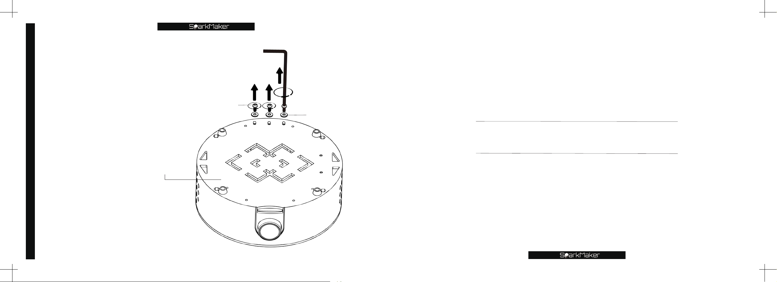
Use the big hex wrench
to turn counterclockwise
Replace the light board
to unscrew the three
round head screws on
the bottom of the printer.
Big hex wrench
Round head screw
Washer
Adjustment of Z axis
Bottom of the printer
76
Page 41
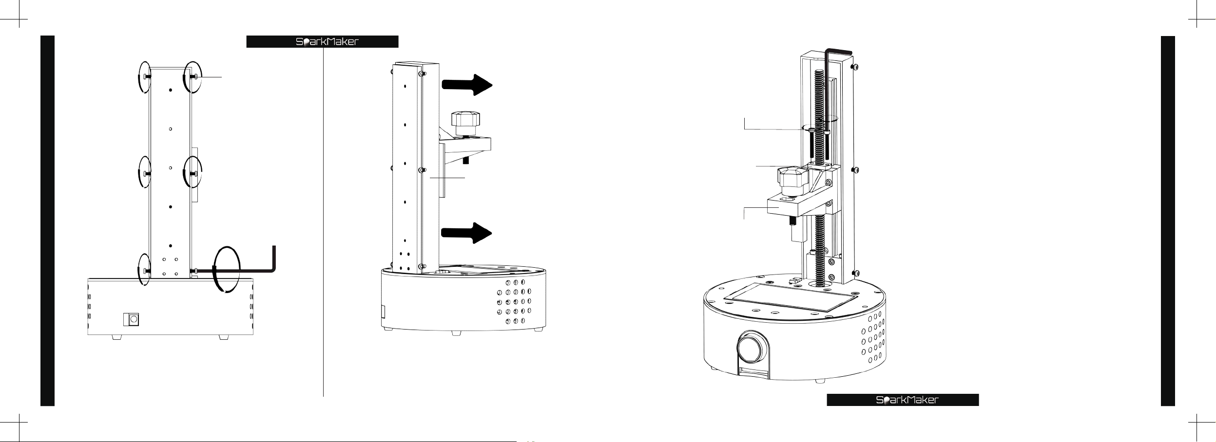
Pan head screw
Big hex wrench
Round head screw
Adjustment of Z axis
Use a small hex wrench to loosen the
6 pan head screws on both sides of
78
the Z-axis counterclockwise.
Small hex wrench
Apron
Remove the apron along the front
of the printer.
*
Notice:
Please carefully remove the apron.
Copper nut
Cantilever
Use the big hex wrench to turn
counterclockwise to unscrew
the two round head screws
that secure the copper nut.
*
Notice:
Please take good care of the removed
parts.
Adjustment of Z axis
79
Page 42
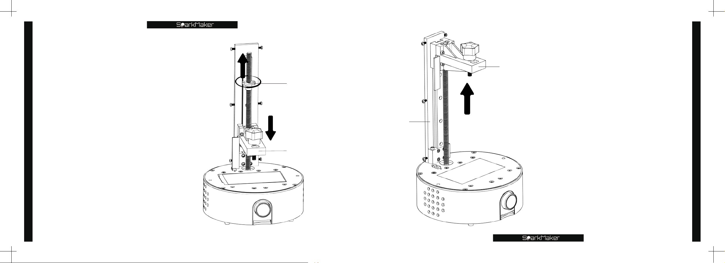
Adjustment of Z axis
fall along the guide rail and then
rotate counterclockwise by hand
to screw out the copper nut from
above.
*
Notice:
Pay attention to the balls in the slider
when moving the slider to prevent it from
falling.
At this time,the cantilever will
Copper nut
Cantilever
Slide
Cantilever
Move the cantilever along the
guide rail to the top,and the
cantilever is parallel to the
working panel.
*
Notice:
When moving the slider,please be careful
not to pull the cantilever out of the guide rail
to prevent the balls in the slider from falling
out.
Adjustment of Z axis
80
81
Page 43
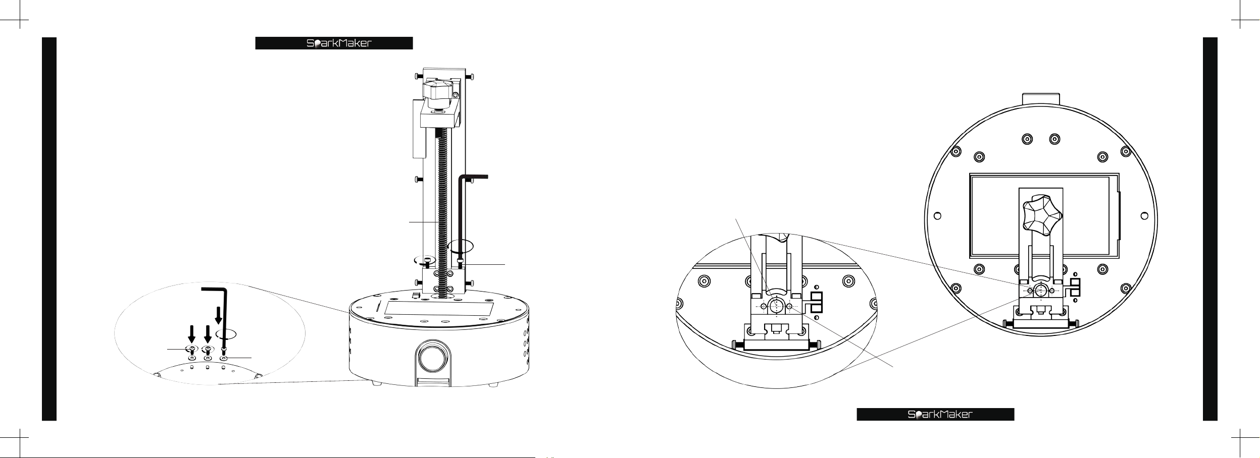
Use the big hex wrench to
adjust the two positioning
round head screws for
mounting the Z axis and the
three round head screws on
Adjustment of Z axis
the bottom of the printer.
*
Notice:
After adjusting the installation,the
screws should be properly tightened.
Big hex wrench
Screw
Big hex wrench
Round head screw
Keep the two copper nut
mounting holes at the top of
the cantilever on the same
horizontal line as the center of
the screw.
*
Notice:
Move the cantilever to the top and adjust.
Copper nut mounting hole
Adjustment of Z axis
Round head screw
82
Washer
Screw
83
Page 44
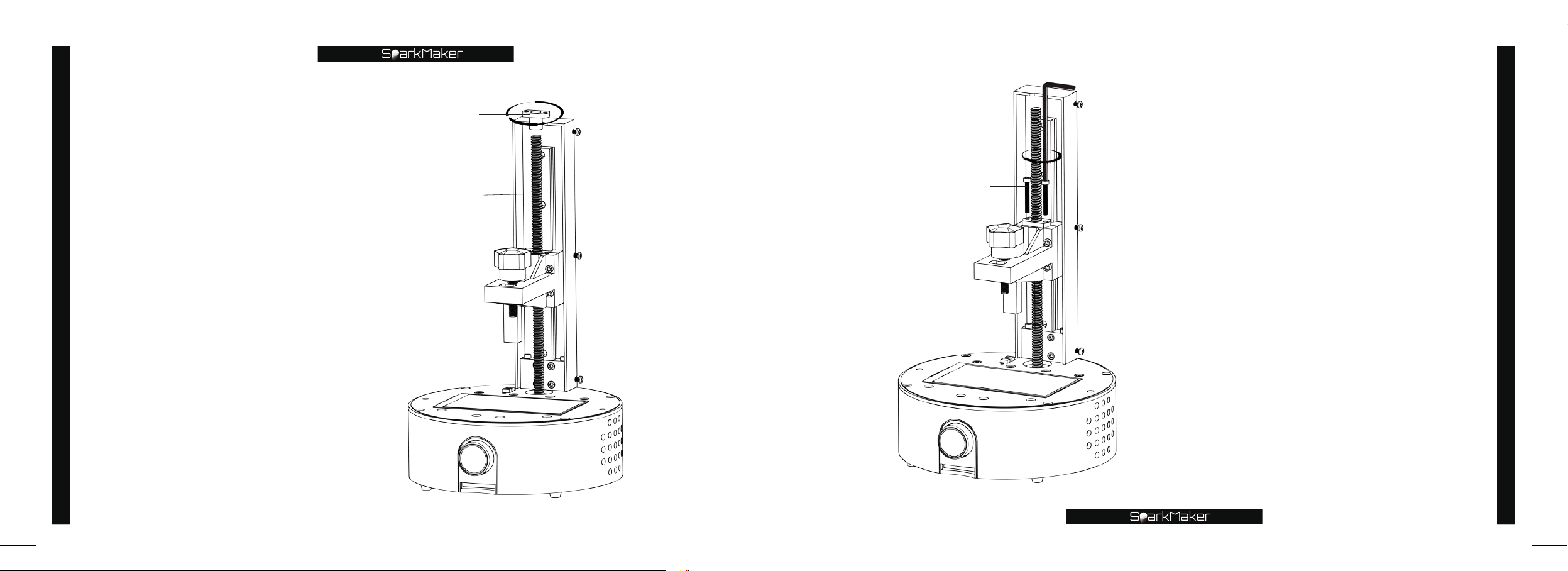
Adjustment of Z axis
Screw the copper nut
clockwise from the top of
the screw into the screw.
*
Notice:
Do not reverse the position of the
copper nut.
Copper nut
Screw
Round head screw
Big hex wrench
Rotate the two round
head fixing screws of the
copper nut clockwise with
the big hex wrench.
*
Notice:
Do not tighten the two fixing
screws of the copper nut too
much,otherwise it will not be able
to move normally.
Adjustment of Z axis
84
85
Page 45
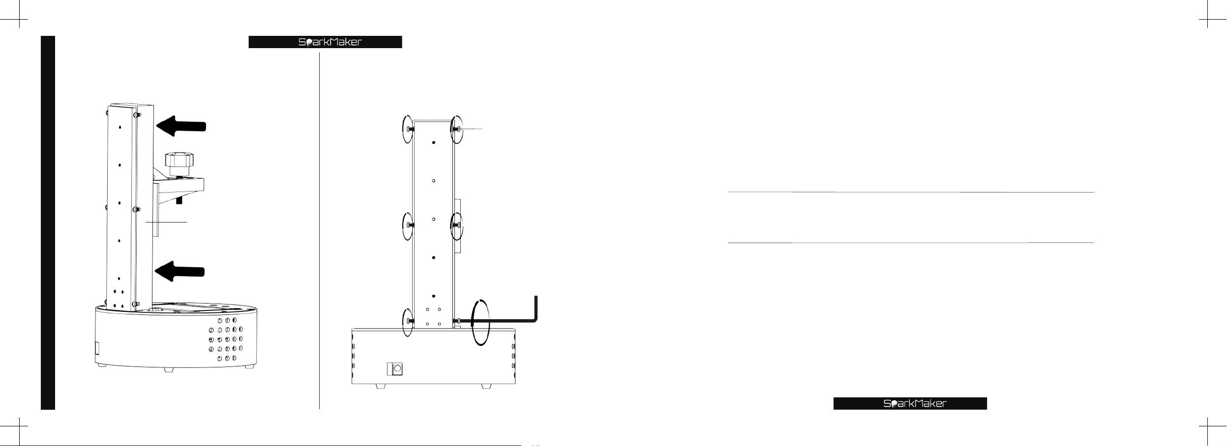
Put the apron back on the Z axis.
Adjustment of Z axis
Tighten the 6 screws on both sides
of the Z-axis with the small hex
wrench.
Pan head screw
86
Apron
Filtration residue
Small hex wrench
Page 46
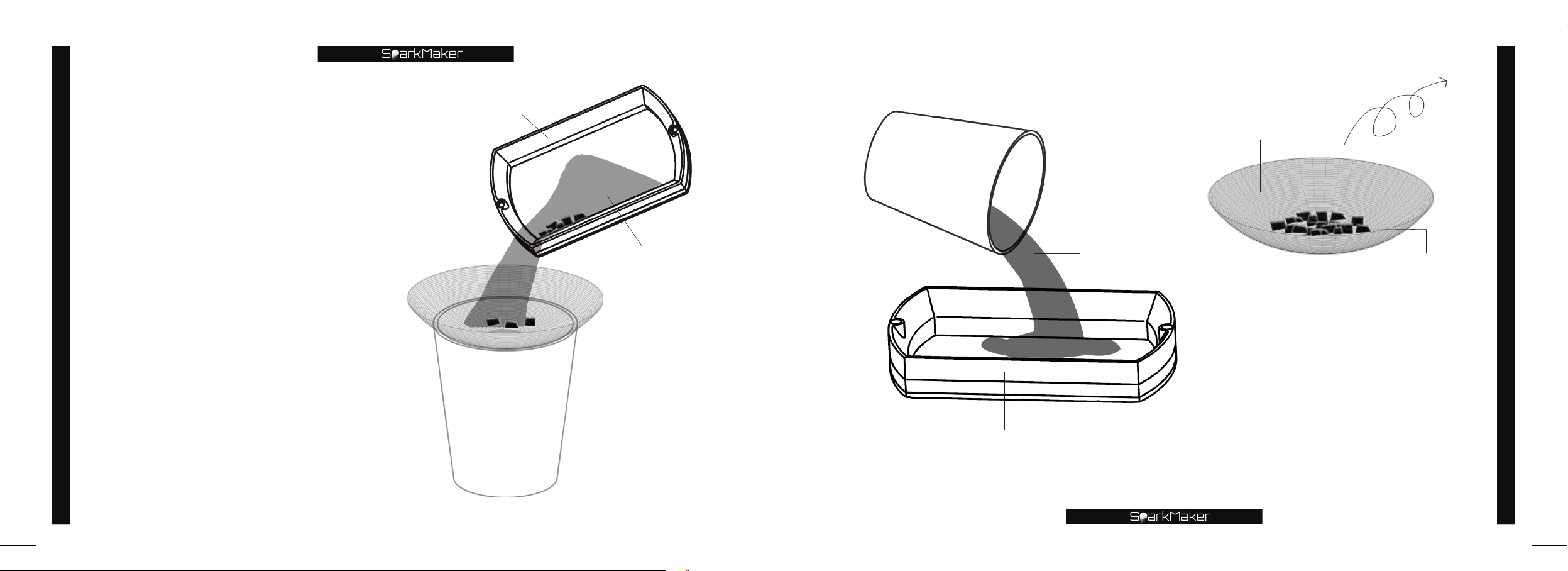
Remove the tank and slowly
Filtration residue
pour the resin along the corner
of the tank through the filter
into the plastic cup prepared in
advance.
Filter
Tank
Plastic cup
Resin
Residue
Plastic cup
Tank
Resin
Filter
Residue
After all the residue has
been filtered off,the residue
is thrown away and the resin
in the plastic cup is poured
back into the tank to use.
*
Notice:
Please clean the resin on the outer wall
of the tank in time to avoid damage to
the LCD screen.
Filtration residue
88
89
Page 47
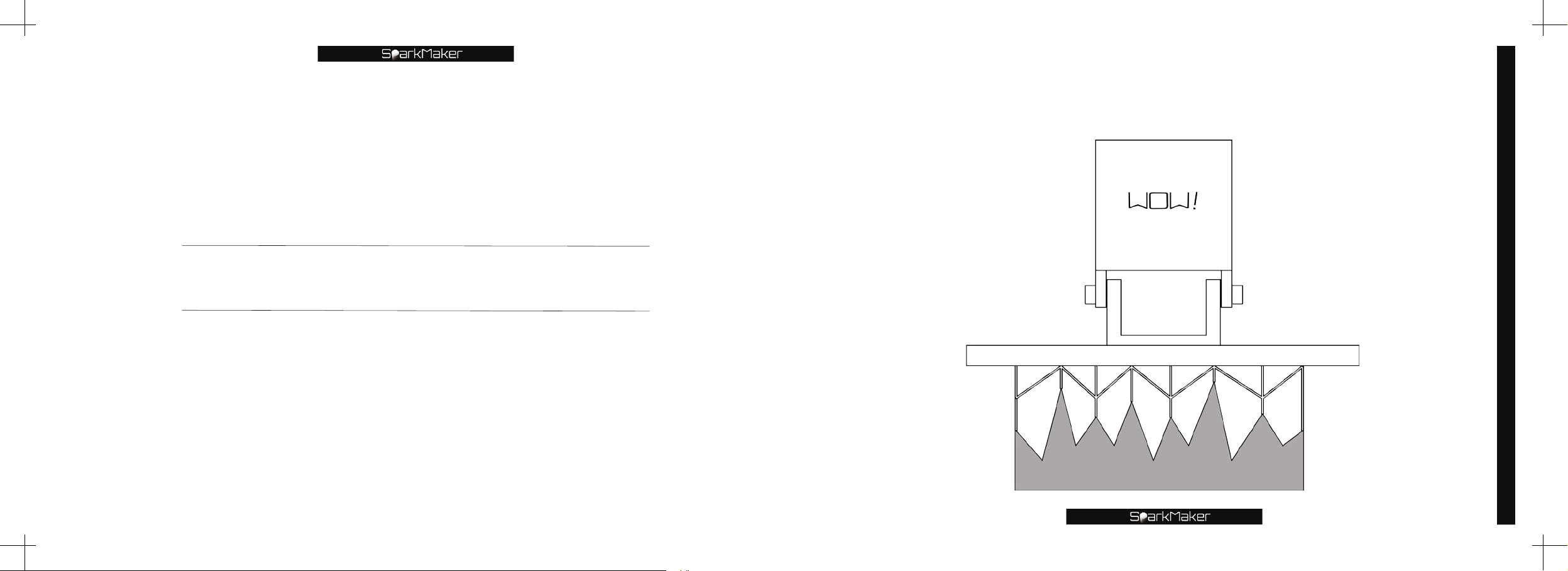
Add support
For such a model with the lowest point feature,support must be
added at its lowest point,otherwise the model will fail to print.
Add support
91
Page 48
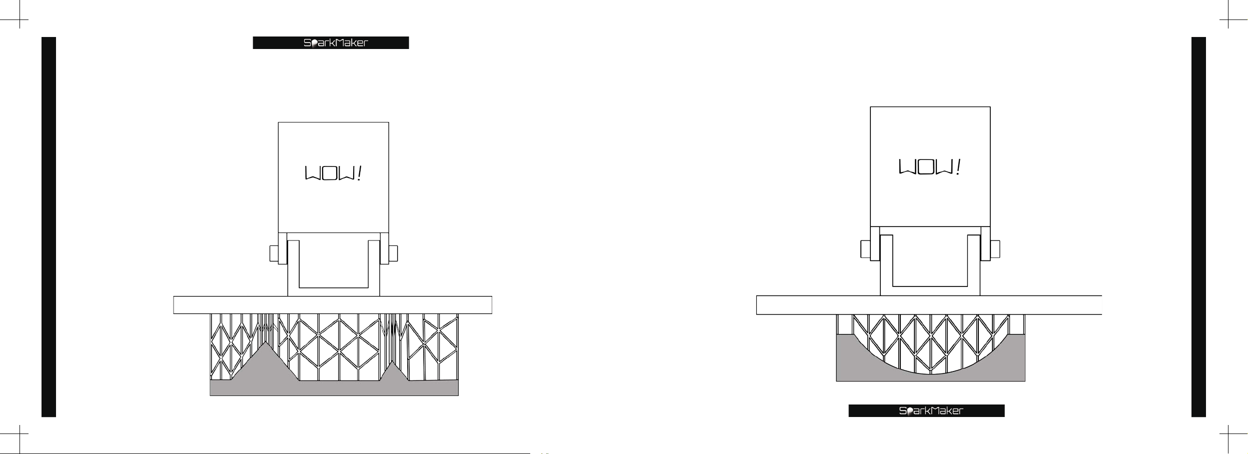
For such a model with the lowest point feature,it should start from
the lowest point and add support from dense to sparse.
For such a model with large spans feature,some supports should be
added in the middle of the bridge appropriately.
Add support
92
Add support
93
Page 49
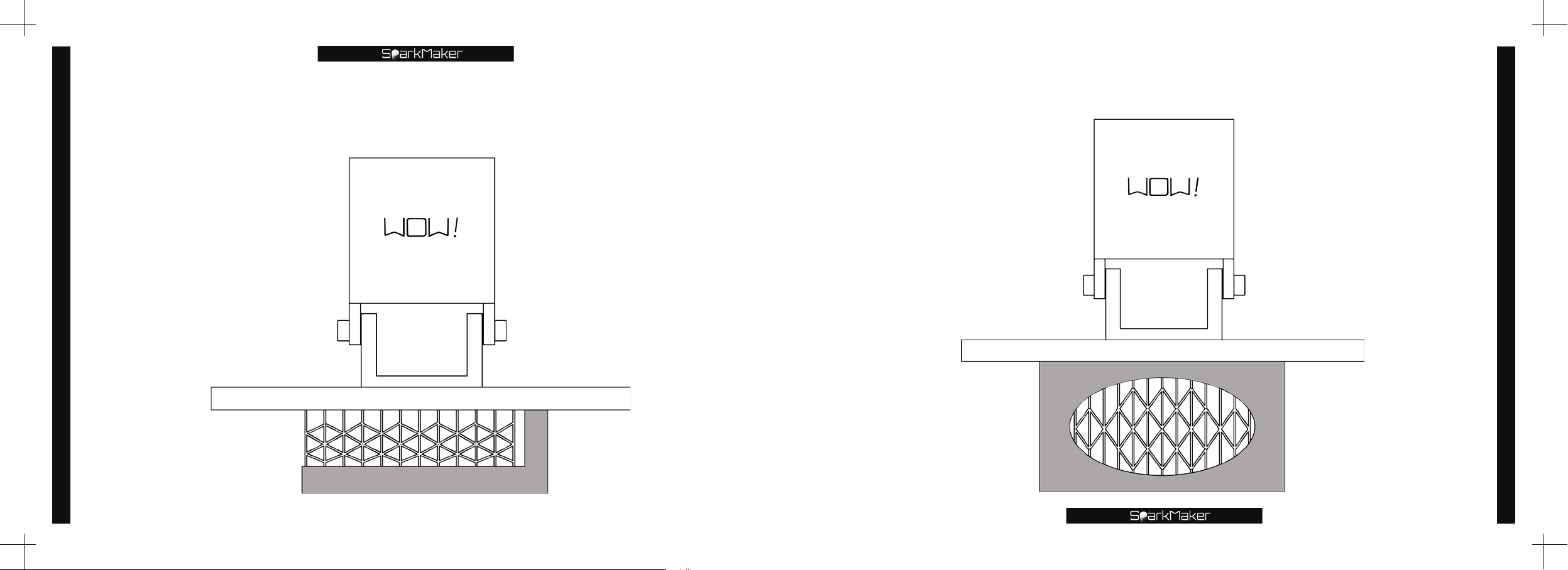
For such a model with cantilever feature,it is necessary to add
support evenly in its cantilever position.
For such a model with large internal hollow and large span feature,it
is necessary to add support evenly in the hollow area.
Add support
94
Add support
95
Page 50
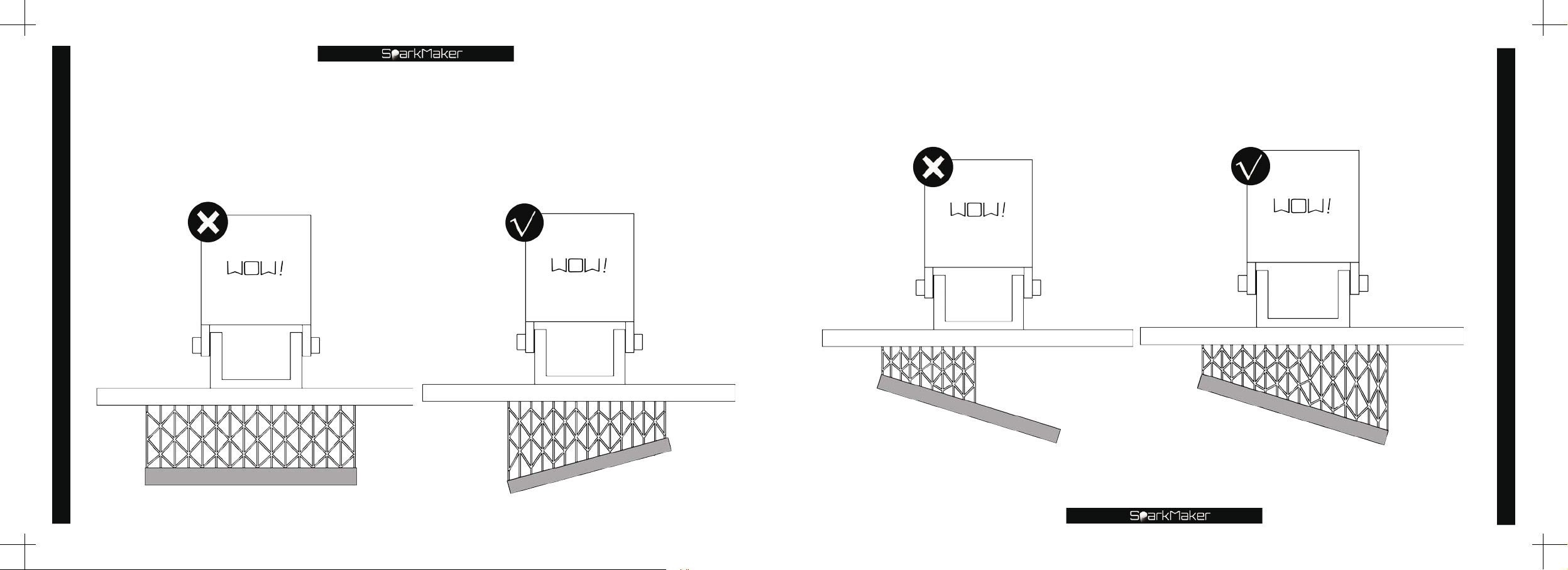
For such a model with large volume,higher height and large span feature,
you can tilt an angle and then add support evenly.The printing quality
will be better than flat printing,and the printing time will be greatly
shortened,and the support will be added more easily.
For such a model with large volume,higher height and large span
feature,all areas should be add support evenly.
Add support
96
Add support
97
Page 51
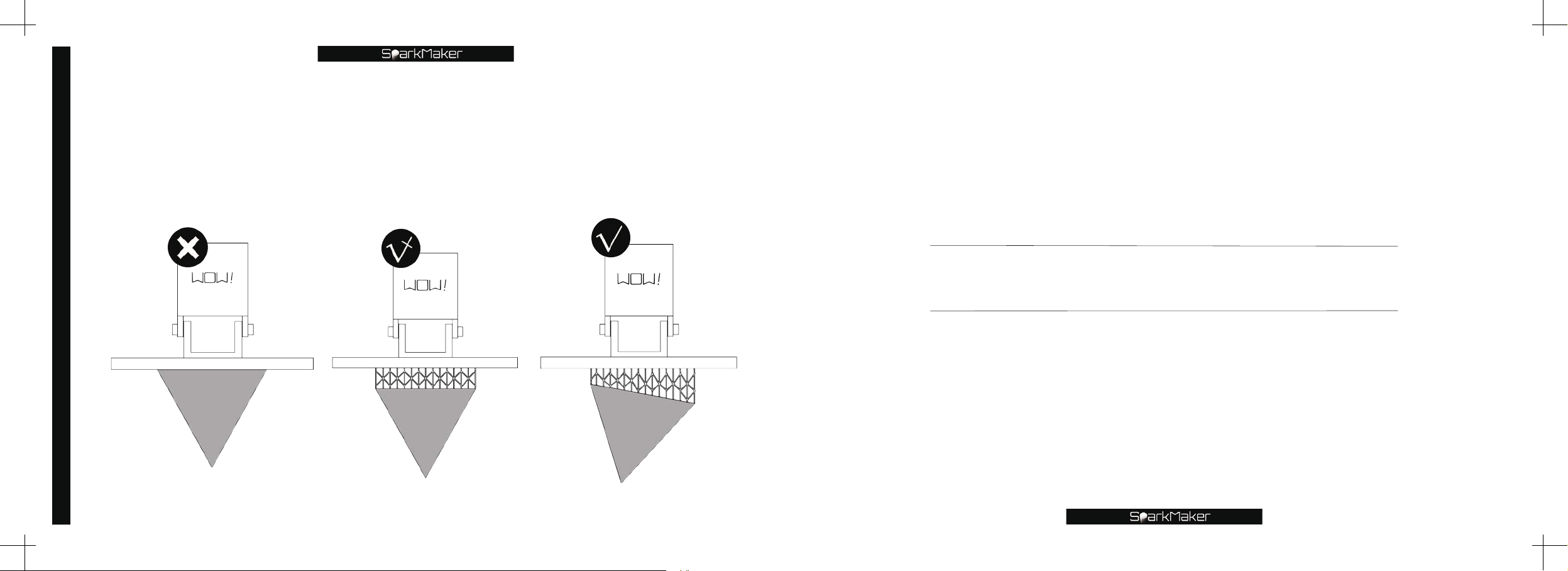
For such models with large-area bottom feature,in order to avoid the
FAQ
adhesion between the bottom surface making the platform too difficult
to remove,and to avoid deformation of the bottom layer due to excessive
exposure,the model should be tilted at an appropriate angle and raised a
distance before adding support evenly.
Add support
98
Page 52
FAQ
100
©How to get a print model?
Download the print file
❶
version)
❷
❸
le that can be printed directly from the ofcial
Download the STL le from the 3D Print Model website or convert the model le to the STL le format.
Design the model using computer 3D design software and then export the model to a le in STL format.
"print.wow"(for
SparkMaker
SparkMaker
version)or "print.fhd" (for
website
(www.sparkmaker3d.com).
SparkMaker FHD
©How to update the firmware?
Download the latest update rmware from the ofcial
❶
Unzip the downloaded update rmware
❷
SparkMaker FHD
Turn off the power to
❸
Insert the
❹
Power on the
❺
The indicator on the knob will turn purple(
❻
knob will turn purple
Use your computer to delete the update rmware from the SD card.
❼
Finish updating the rmware and start printing.
❽
version)
SD
card into the
SparkMaker.
and save it on the SD card.
SparkMaker
SparkMaker
and then the light started ashing,nally turn green,which means the update is successful.
)
,
update.wow (for
.
card slot.
if it is
SparkMaker
SparkMaker FHD
website
SparkMaker
version,you need click the knob when
(www.sparkmaker3d.com)
version) or update-FHD.wow (for
.
©How can I check if there is a problem with the print file?
Open the
computer software and check if the pattern of each layer of the slice is normal.
*.wow(for
SparkMaker
version)or *fhd(for
SparkMaker FHD
version)
slice le with
SparkStudio
©Why does the indicator change from green to red and then quickly change back to
green when the SD card is inserted and the knob is clicked?
The SD card is not recognized or has been damaged. A new SD card needs to be replaced. The SD card
❶
should be a
card is completely unlocked by hardware
The direction or depth of the SD card insertion is incorrect. It needs to be adjusted to make the metal contacts
❷
contact.
C10 high-speed
card with a capacity lower than
and the metal contacts are free of stains.
,
32GB
.
The le system format is
FAT32
.
The SD
If you use the knob to control the printer
❸
SparkMaker
be recognized.
Open the print le with
❹
version)or "print.fhd" (for
SparkStudio
and check if there is a problem with print le.
check if the print file named in the SD card is
,
SparkMaker FHD
version)
.
If other le names are used
"print.wow"(for
they will not
,
©Why does the platform continue to drop without stopping after clicking the knob to
print?
The platform is not leveled
❶
been triggered,and the platform should be leveled rst.
There is residue on the platform or in the tank
❷
switch has not been triggered. The residue on the platform and in the tank should be cleaned.
The trigger piece on the platform is not aligned with the lower photoelectric switch. The trigger piece should be
❸
inserted into the middle notch of the photoelectric switch.
The photoelectric switch is damaged or the photoelectric switch is not installed correctly.
❹
so that it cannot be lowered to the lowest point. The photoelectric switch has not
,
so that it cannot be lowered to the lowest point. The photoelectric
,
FAQ
©Why is the screw movement not smooth?
The Z axis is not corrected. The direction of the lead screw and the guide rail are not parallel
❶
motion resistance and needs to be corrected again.
The screw needs to add some grease.
❷
The screw is blocked by the cured resin and needs to be cleaned.
❸
The copper nut mounting screw is too tight
❹
adjusted to make the screw move smoothly.
the screw is stuck,and the copper nut mounting screw should be
,
which creates
,
©Why does the model need to add support?
The gravity and release force need to be overcome during the printing process. Therefore,the minimum point and
the suspended part of each layer must be supported. In order to ensure that the model is not deformed and not
broken
©What is the printing time of
the model needs to add more support to strengthen the support structure to overcome the release force.
,
SparkMaker
SLA 3D printer?
101
Page 53
FAQ
102
SparkMaker
number of printed layers,regardless of the cross-sectional area. In the case of the same layer thickness,the shorter
the model
printing. It should be noted that the larger the layer thickness
worse the printing quality.
SLA 3D printer is a face-to-layer printing method. The printing time is only related to the height,the
the less time is spent printing; at the same height,the larger the layer thickness is,the less time is spent
,
the longer the single layer exposure time and the
,
©How much resin is suitable for pouring into the tank?
Less than
damage to the LCD screen.
240ml
resin should be poured into the tank. Do not pour in too much resin, it will result in resin overow
©Why is the resin placed in the tank solidified?
The tank is placed on a balcony or other place with a strong light source to cause the resin to cure.
❶
The UV light emitted from the side of the machine is reected and applied to the surface of the tank to solidify it.
❷
©When the liquid photosensitive resin in the tank is printed,there are a lot of
bubbles,which will affect the printing? How to remove?
The liquid resin can place for a period of time to eliminate air bubbles.
❶
Keep the liquid resin without bubbles and print out the model without bubbles.
❷
©Why are there bubbles inside the printed model?
When printing
❶
When printing
❷
appropriately.
bubbles are present in the liquid resin in the tank.
,
the falling speed is too fast,and bubbles are generated.The falling speed should be adjusted
,
©What effect does temperature have on printing?
The printing process should be controlled within the indoor temperature range of
❶
Printing in lower temperature requires an increase in exposure time.
❷
The normal printing temperature is
❸
by
Excessive temperature will cause the FEP lm to deform and damaged the liquid crystal.
. The curing speed is increased by
30%
25 degrees
30%
. For every
for every
10 degrees
10 degrees
reduction
but it will eventually reach a stable value.
,
24-35.
the curing speed is reduced
,
©Why is there nothing stuck on the aluminum plate of the printing platform after the
printing is finished,and the residual resin is stuck on the FEP film at the bottom of the
tank?
The printing platform is not leveled and needs to be leveled correctly.
❶
The bottom layer exposure time set is too short and you need to increase exposure time. If a third-party resin
❷
is used
layer exposure parameters to
❸
❹
entire model. You need to check the position of the model or set the sinking print model.
❺
on the LCD screen.
the user needs to adjust the printing parameters by himself. It is recommended to adjust the bottom
,
200 seconds
The set lifting speed is too fast and the model is broken
The contact surface between the model and the printing platform aluminum plate is too small to cover the
Check the FEP lm on the top and bottom of the tank
.
so it is necessary to reduce the lifting speed.
,
and whether there is any obstruction or resin residue
,
©Can I continue printing if printing is suddenly interrupted?
SparkMaker
No
,
3D printer does not have this feature yet.
©What should I do when the print is interrupted accidentally?
Turn off the power and remove the print platform and tank.
❶
Use a shovel to clean the residual solids on the platform and the tank and start printing again.
❷
©Why is the bottom of the model stuck to the printing platform and the residual resin
is stuck on the FEP film,after the printing is finished?
The support of your model is too thin to pull the model.
❶
The support of your model is too little to hold the model.
❷
The layer exposure time is insufcient
❸
The model you print is too large
❹
lifting distance should be increased.
Check the FEP lm up and down
❺
some of the support is broken and it is difcult to pull the model
,
the lifting distance is not enough,the model is difcult to release,and the
,
whether there is any obstruction or resin residue on the LCD screen.
,
.
FAQ
103
Page 54
FAQ
104
Check if the UV LED on the light board is fully illuminated when printed
❻
The lifting distance is too large
❼
Open the print le with
❽
SparkStudio
and the position is misplaced when moving up and down for a long distance.
,
and check for any problems with the sliced graphics.
and if the brightness is different.
,
©Why is a cuboid block that is the size of the screen printed on the printing platform
after printing is finished, or not printed anything?
If the LCD screen is damaged or the contact is poor
❶
cable and try to connect again. If it cannot be solved,replace the new LCD screen.
Check that the lamp bead on the lamp board is lit normally when printed.
❷
Open the print le with
❸
The copper nut mounting screw is too tight
❹
adjusted to make the screw move smoothly.
SparkStudio
and check for any problems with the sliced graphics.
the screw is stuck,and the copper nut mounting screw should be
,
it will be completely transparent. Check the LCD screen
,
©Why is the LCD screen not working?
The resin drop into the LCD screen and damage the LCD screen.
❶
The residual resin residue on the tank or platform crushes the LCD screen during printing.
❷
The connection cable inside the LCD screen is loose during transportation.
❸
Check the FEP lm in the tank
❹
and whether there is any obstruction or resin residue on the LCD screen.
,
©Why does the bottom of the model swell?
In order to make the model stick to the bottom layer of the platform,the bottom exposure time is longer than the
normal layer,and the long under layer exposure time will cause the resin around the bottom layer expand,you can
lift the model a distance and then add the bottom support.
©The aluminum plate of the printing platform has been scratched by the tool after
repeated use,can it be used?
Slight scratches have little effect on the model and it can be used continuously,and the rougher the metal
the stronger the adhesion.
plane
,
©How to improve the printing speed?
Use a resin that cures faster.
❶
Use a larger layer thickness to save printing time.
❷
Increase the speed of descent and the speed of lifting as appropriate.
❸
©Why is the support broken during the printing process?
The layer exposure time is not enough
❶
If the support is too thin
❷
The surrounding support is not dense enough,need to add more dense support.
❸
Check the FEP lm up and down
❹
The lifting speed is too high and damaged the support
❺
The Z-axis motion is not smooth. Correct the Z-axis and add some grease.
❻
If the hardness of the resin is too low
❼
a thicker support should be used.
,
the layer exposure time should be increased appropriately.
,
whether there is any obstruction or resin residue on the LCD screen.
,
the lifting speed should be reduced appropriately.
,
a resin with a higher hardness should be used.
,
©Why is the cross section of the model deformed?
Because the exposure time is too long or insufcient
❶
The resin selected is not in the specied curing band.
❷
Some points are are not adding support and the model part is sunken and deformed.
❸
The platform handle is not tightened when printing.
❹
The tank is not installed well.
❺
Check the FEP lm up and down
❻
If the hardness of the resin is too low
❼
whether there is any obstruction or resin residue on the LCD screen.
,
a resin with a higher hardness should be used.
,
the exposure time should be adjusted appropriately.
,
©Why is the height of the printed model incorrect?
The platform is not leveled.
❶
Z-axis stuck
❷
The platform handle is not tightened when printing.
❸
The underlying exposure time is too long and the bottom layer is inated.
❹
Because the exposure time is too long or insufcient
❺
the Z-axis should be corrected and grease added.
,
the exposure time should be adjusted appropriately.
,
FAQ
105
Page 55
FAQ
106
The resin selected is not in the specied curing band.
❻
©How to deal with a layer of resin residue on the LCD screen?
The resin that is cured on the LCD screen is usually a lm,which can be peeled off by hand or gently scraped off
with a knife.
©Why are there ladder stripes in the Z axis direction of the print model?
SparkMaker
thickness,there will be a ladder stripes in the Z-axis direction of the model. This is caused by the molding principle
itself,and the lower layer thickness can be selected to reduce the ladder stripes.
SLA 3D printer is a surface-curing method for layer-by-layer printing. In the case of high layer
©Why is there a pixel pattern in the XY direction of the print model?
SparkMaker
model. White or light-colored resins can be used to visually reduce pixel patterns.
SLA 3D printers use LCD screens as imaging components,so pixel patterns are inevitable on the
©Why are there details or missing features on the print model?
The model features or details are too small
❶
Check that these details or features lack support or support density and thickness is incorrect.
❷
Open the slice le in the computer software and check if the image is missing.
❸
Check if the UV LED on the light board is not lit when printing.
❹
Check for obstructions or residual glue on the LCD screen.
❺
Check the top and bottom of the FEP lm of the tank for obstructions or residual resin.
❻
If the hardness of the resin is too low
❼
,
and the printer resolution is difcult to meet the printing.
,
a resin with a higher hardness should be used.
©Why did the model stop printing before it finished printing?
Check if the print le is saved completely.
❶
Check if there is an unexpected power failure during printing.
❷
Check if the power socket is stable.
❸
Check if the SD card is plugged in.
❹
Check if the knob rotates smoothly and whether it a steady ashing red light during printing.
❺
Check that the Z-axis motion is smooth.
❻
Check if the resin in the tank is sufcient.
❼
©Note on the use of the LCD screen
The normal life of the LCD screen is about
❶
The resin or other liquid on the LCD screen will damage the LCD screen.
❷
Excessive pressure will break the LCD screen.
❸
800 hours
and the LCD screen warranty period is
,
2 months
©Note on the use of FEP film
Carefully protect the FEP lm from scratches.
❶
After a period of use
❷
Please clean the resin residue on the upper and lower sides of the FEP lm in time to avoid printing failure.
❸
When installing the tank
❹
The FEP lm is stretched at the bottom of the tank. This material has low adhesion
❺
has a long service life. Its function is elastic release,and materials such as glass and ordinary plastic lm cannot
be replaced.
if there are a lot of obvious creases on the FEP lm,replace the new FEP lm in time.
,
the FEP lm should be in close contact with the LCD screen.
,
can pass ultraviolet light,and
,
.
©Precautions for the use of the tank
If the resin in the tank is not used for a long time
❶
in the tank for more than two weeks.
Please do not pour in excess resin to prevent the resin from overflowing and causing damage to the LCD
❷
screen.
Please do not put the resin into the screw mounting hole and the outer wall of the tank
❸
screen to be damaged. If it accidentally ows in,please clean it in time.
When installing the tank
❹
The slot mounting screws should be balanced and tightened to tighten the FEP lm.
❺
the FEP lm should be in close contact with the LCD screen.
,
please pour the resin into the storage container. Don't store it
,
which will cause the LCD
,
©Print model considerations
The model le must have no le errors such as broken faces and le corruption.
❶
FAQ
107
Page 56
FAQ
108
The long-span cantilever position
❷
strengthened and so on in the model le are all added with the right thickness,the right number of supports and
the correct bottom valve.
The slice parameters such as the layer thickness
❸
The slice le is completely saved in the SD card
❹
there is no fault in the middle.
If you use the knob to control the printer
❺
version)or "print.fhd" (for
SparkMaker FHD
the lowest point position of the layer,the position that needs to be
,
exposure time,and lift speed of the print le are set correctly.
,
the bottom surface is completely attached to the ground,and
,
you need to name the print file as
,
version)
and save it to the SD card.
"print.wow"(for
SparkMaker
©How to check if the LCD screen and light board are working properly?
First remove the tank and printing platform,then insert the SD card with the printed file,press the knob to start
printing,then wait for the light board to light up,the LCD screen displays the image,observe whether the image is
normal,the light on the light board Whether the beads are normally lit.
©Problems about the loss of LCD screen and light board.
SparkMaker
The
backlight as the light for curing the resin. Because the LCD screen is exposed to UV light,it will be damaged under
long-term use. It has a life of
light transmittance is poor,the exposure time is obviously longer or the graphics or the like cannot be displayed
normally,the LCD screen should be replaced in time. The UV LED board will also wear out during long-term
exposure. It can be kept for
intensity is obviously weakened,the exposure time is obviously longer or there are some UV LEDs don't light or
weak,the light board should be replaced in time.
SLA 3D printer uses a liquid crystal screen as a graphic display component and uses a UV
2-3 months
2-3 months
under frequent use. When the LCD screen has black spots and the
without signicant light energy loss under frequent use. When the light
©Do I need to leveling the platform before every print?
SparkMaker
The
proper leveling,if you do not adjust the Z axis,do not loosen the four screws on both sides of the platform,and do
not reinstall the resin tank,normally you don't need to leveling the platform again.
SLA 3D printer uses a high-precision photoelectric switch with high repeatability,so after
Basic operational concept
Page 57
©Layer thickness
The thickness of the layer printed by the printer each tim,the supported thickness range is
0.1mm~0.025mm
The
0.1mm
The time and precision of
The
Basic operational concept
0.025mm
©Layer exposure time
In addition to the bottom layer,each layer is exposed to UV light for curing. Different resin are also have
different in layer exposure time.
layer thickness prints faster and the printing accuracy is relatively low.
layer thickness prints more accurately and prints for a longer period of time.
©Bottom layer exposure time
The time of bottom layer cured by the UV light,because the bottom layer is the base layer that supports
the entire model,the exposure time is longer. Different resin are also have different in bottom layer
exposure time.
©Factors affecting exposure time:
1.
Type of resin:
Different resins are not sensitive to light,so different resins cure at different times.Generally,the gray
resin bottom layer exposure time is longer.
2.
Model factor:
Structures such as small cylinders,thin walls,and thin supports need to increase the exposure time of
❶
the layers.
Structures such as small holes and small gaps need to reduce layer exposure time.
❷
The model with an excessively large underside requires an increase in the bottom layer exposure
❸
in order to adhere rmly.
time
3.
110
Layer thickness factor
The larger the layer thickness,the longer the exposure time required,and the smaller the layer
:
.
0.05mm
layer thickness printing tend to be relatively balanced.
:
:
:
thickness,the shorter the exposure time required.
©Exposure intensity
The light intensity of the light board,this item is basically a xed value of
need to be adjusted.
©Lifting distance
After printing each layer,the model is separated from the tank and lifted upwards. In general,the larger
the cross-sectional area of the model or the more dispersed the model layout,the larger the lifting
distance required;the thicker the photosensitive resin,the larger the lifting distance required.
©Lifting speed
The rate at which the resin is lifted upwards to separate the model from the FEP membrane after the
resin has cured. When the model is separated from the FEP membrane,in order to ensure that the
integrity of the model is not broken,the lifting speed should be reduced,so the platform lifting speed
should be less than the falling speed. Under normal circumstances,there are small features or models
using ne support,the lifting speed should be reduced; the softer resin after printing should reduce the
lifting speed; the larger the cross-sectional area of the model or the more dispersed the model layout,the
lower the lifting speed.
:
©Decline speed
After the resin is cured,the platform is lifted and the speed of the lm is lowered. In general,there are
small features or models that use ne support,and the speed of descent should be reduced; the softer
resin after printing should be reduced in speed.
:
:
:
255bit
and generally does not
,
Basic operational concept
111
Page 58
©
What does the warranty cover?
Terms & Conditions
The 6-month warranty covers all functional aspects of
1.
normal use,excluding
The 2-month warranty covers
2.
©
What does the Warranty NOT cover?
Man-made damage or any problem caused by misoperation.
1.
Self-retting and self-dismantling are not covered by the warranty.
2.
Damage caused by using third-party resin or parts will void the warranty.
3.
©
When does the Warranty begin?
It starts from the date of receipt of the goods.
1.
LCD
screen,the resin tank,and
LCD
screen,the resin tank,and
SparkMaker
UV LED
backlight.
UV LED
3D printer under
backlight.
Terms
&
Conditions
113
Page 59
Customer service
How to solve the problem
©
?
Send an email、leave a massage on the ofcial
•
on ofcial Facebook group.
•
Email
•
Official
•
Official Facebook group
https://www.facebook.com/groups/
:
SparkMaker
website
:
:
140657399943252/
SparkMaker
https://www.sparkmaker3d.com
website or ask experienced users
 Loading...