

Page 1

Model Name: WVTR-141
Brand Name: SparkLAN
Wireless ATA
User Manual
Version 1.0
Page 2

Copyright Statement
No part of this publication may be reproduced, stored in a retrieval sy stem, or transmitt ed in any
form or by any means, whether elect ronic, me chanical, photocopyi ng, recording, or otherwise
without the prior writing of the publisher.
Federal Communication Commission Interference Statem ent
This equipment has been tested and found to comply with the limits for a Class B digital device,
pursuant to Part 15 o f the F CC R ules. These limits are designed to provide reasonable protection
against harmful interference in a residential installation. This equipment generates, uses and can
radiate radio frequency energy and, if not installed and used in accordance with the instructions,
may cause harmful interferenc e to radio communications. However, there is no guarantee that
interference will not occur in a particular installation. If this equipment does cause harmful
interference to radio or television reception, which can be determined by turning the equipment off
and on, the user is encouraged to try to correct the interference by one of the following measure s:
- Reorient or relocate the receiving antenna.
- Increase the separation between the equipment and receive r.
- Connect the equipment into an outlet on a circuit different from that to which the receiver is
connected.
- Consult the dealer or an experienced radio/ TV technician for help.
FCC Caution: Any changes or modifications not expressly approved by the party responsible for
compliance could void the user's authority to operate this equipment.
This device complies with Part 15 of the FCC Rules. Operation is subject to the following two
conditions: (1) This device may not caus e harmful interf ere nce, and (2) this device m ust a ccept any
interference received, including interference that may ca use undesired operati on.
IMPORTANT NOTE:
FCC Radiation Exposure Statement:
This equipment complies with FCC radiati on exposure li mits set forth for an u ncontrolled
environment. This equipment should be installed and operated wit h minimum distan ce 20cm
between the radiator & your body.
This transmitter must not be co-located or operating in conjunction with any other an tenna or
transmitter.
The availability of some specific channels and/or operational frequency bands are country
dependent and are firmware programmed at the factory to match the intended destination. The
firmware setting is not accessible by the end user.
Page 3

Table of Contents
PART I INTRODUCTIONS................................................................1
Ch. 1 Introduction to VoIP............................................................................................................2
1.1 Advantages of VoIP to Businesses...................................................................................2
1.2 SIP – Most Popular VoIP Protocol.....................................................................................3
1.2.1 SIP Identities..................................................................................................................................3
1.2.2 Servers in SIP World......................................................................................................................3
1.3 VoIP-Friendly Networking Concepts .................................................................................4
1.3.1 NAT, Network Address Translation..........................................................................................................4
1.3.2 STUN, Simple Traversal of UDP through NAT.............................................................................5
1.3.3 Voice Codec...................................................................................................................................5
Ch. 2 Introduction to Network application....................................................................................6
2.1 Operation Mode s................................................................................................................6
2.2 Wirele ss Modes..................................................................................................................6
2.3 Topologies of Net work Appli cation....................................................................................7
Ch. 3 Knowing WIFI-ATA.............................................................................................................9
3.1 Overview of WIFI-ATA........................................................................................................9
3.2 Key Features of WIFI-ATA...............................................................................................10
3.3 Outlook of WIFI-ATA........................................................................................................11
3.4 Web Configuration E nvironment......................................................................................13
PART II ATA SETTINGS.................................................................14
Ch. 4 Configuring WIFI-ATA......................................................................................................15
4.1 Quickly Set up (Setup Wi zard)..........................................................................................16
4.2 Operation Mode................................................................................................................21
4.3 TCP/IP Settings................................................................................................................22
4.4 VoIP Settings....................................................................................................................27
4.5 Wirele ss setting s...............................................................................................................34
4.6 Firewall settings................................................................................................................42
4.7 Management.....................................................................................................................45
PART III ILLUSTRATIONS.................................................................................. 49
Ch. 5 FAQ & Troubleshooting........................................................................................................50
5.1 How can I m ake a phone call?.........................................................................................50
5.2 How can I pick u p the call waiting while I’ m on the phone?...........................................50
5.3 How can I make a 3-way conference call ?.....................................................................51
5.4 How can I transfer a call to others?.................................................................................51
5.5 Why can’ t I login to the WIFI -ATA?..................................................................................51
5.6 Why can’t I access the Internet?......................................................................................51
5.7 Why can’t I make VoIP phone calls to others?...............................................................52
5.8 WIFI-ATA do esn’t respo nd correctl y to key press some times.......................................52
Page 4

Part I Introductions
Topics in Part I:
z Ch. 1 Introduction to VoIP
z Ch. 2 Introduction to Network application
z Ch. 3 Knowing WIFI-ATA
Page 5

Ch. 1 Introduction to VoIP
VoIP stands for Voice over Internet Protocol, which means transmitting voice over the
most widely accepted network protocol around the world. Internet Protocol networking
is widely supported by almost all kinds of networks. VoIP, however, can also be
implemented inside LAN only without Internet involved if proper LAN environment is
ready. In addition, with improvements, business class VoIP system can integrate data,
voice, and video in the same network. This takes simplified management rules into
three different systems / networks and results in enhanced performance for all ki nds of
organizations.
Later on, this chapter will guide you through the basic elements of the VoIP and some
related terms involved as below:
z Advantages of VoIP to Businesses
z SIP – Most Popular VoIP Protocol
z VoIP-Friendly Networking Concepts
1.1 Advantages of VoIP to Businesses
Telephony system was invented around 100 years ago by Alexander Graham Bell.
Though telephones expedite the business communications, it’s expensive especially
for international phone calls. Internet Protocol has become the world wide standard.
With remarkable improvements in broadband access, VoIP technology and IP
Telephony, it is about time to provide businesses high quality IP phone calls at
comparably low cost with good reliability. Since voice is transmitted over the Internet
there is no demarcation of any physical boundary, this dissolves any need of being
charged at very high rate for making international phone calls.
IP Telephony focuses on using your existing telephony resources to build a vibrant
communications network that enhances productivity. A common business class VoIP
system provides all the features you’ve been familiar with—voicemail, call waiting, call
forwarding, to name a few—as well as many new exciting features such as making
LOCAL calls at whatever location you may be in the world.
Business world needs reliability and productivity as well. In conventional way,
telephony system and computer-based system are two different networks. Hence, the
two different networks require normally two times of man-power to manage, and they
are hardly managed under a set of unified managing principles. Business class VoIP
2
Page 6

system will be able to provide easy-to-manage, business-driven architecture at a cost
that is competitive with your current expenditures.
1.2 SIP – Most Popular V oIP Protocol
SIP stands for Session Initiation Protocol which an application-layer is signaling
protocol that handles the VoIP phone calls over the Internet. Unlike other VoIP
protocols, SIP handles signaling only, and leverages other SIP-related protocols to
co-work with media sessions accordingly. The simple and flexible enough architecture
brings great chances to SIP for expanding, such as Video phone calls.
Later on, we’ll introduce some terminologies that are common in the VoIP worlds,
especially SIP related. In addition, we strongly recommend the system administrator to
read other VoIP related documents, textbooks to have better unde rstanding i n orde r to
construct a VoIP-friendly network.
1.2.1 SIP Identities
A SIP identity (a.k.a. SIP address or SIP Account) is similar to an email address which
is used for identifying who’s who in the SIP world just like email address used for
identifying the owner. The format of a SIP identity is like an email address, presented
as SIP-Number@SIP-Service-Domain. As the expression shows, there are two major
parts in the SIP account; the SIP-Number and SIP-Service-Domain.
z The SIP number is the first part of the SIP URI that is located in front of the “@”
symbol. A SIP number can be alphabet characters just like in an e-mail address
(johndoe@ITSP-XYZ.com for example) or numeric digits like a regular telephone
number (1234567@ITSP-ABC.com for example).
z The SIP-Service-Domain is the domain name in a SIP URI. It is used to identify who
the service provider is. Normally, it will be the ITSP or the Internet domain name
which your company has.
1.2.2 Servers in SIP World
The architecture of SIP protocol is client-server based. Every SIP device or application
program will act as SIP client and SIP server as well. The SIP device acts as client
when sending out SIP requests, and acts as SIP server once responding to the SIP
requests.
The Servers we talk about here aim only at the device, and / or application program
which are used to provide VoIP services or application program which is used by
3
Page 7

SIP-Service-Domain owner to provide its services to its subscribers. Sometimes, the
SIP Registration Server will be used for distinguishing purpose.
There are three kinds of the server:
z SIP Proxy Server; it relays call signaling, i.e. acts as both client and server
operating in a transactional manner, i.e., it keeps no session state
z SIP Redirect Server; it redirects caller to other servers
z SIP Registrar; it accepts registration requests from users and maintains user’s
whereabouts at a Location Server.
1.3 VoIP-F riendly Networking Concepts
There are many common features from regular router which will block your VoIP
communications, or make your network environment very VoIP-unfriendly. Here are
some topics which you need to take care of, or might be helpful in making a
VoIP-friendly network.
1.3.1 NAT, Network Address Translation
One of the most common features which router provides in order to provide Internet
access to all the computers in your LAN environment is “NAT”. In the simplest case,
NAT changes the source IP address of a packet received from a device to another IP
address before forwarding the packet towards its destination. When the response
comes back, NAT translates the destination address back to the device's IP address
and forwards it to the device.
NAT routers are commonly used to translate private (or internal) IP addresses in
packet headers to public (or external) IP addresses and vice versa. A NAT router
maps a private IP address & port; pairs it to a public IP address & port and whenever
the NAT router receives a packet with that public IP address & port, it knows how to
reroute the packet back to the private IP address & port.
The WIFI-ATA must know the public IP address which you get from your ISP in order
to provide its services. If there is a NAT router between the WIFI-ATA and your
broadband modem then your WIFI-ATA probably has a private IP address. In thi s case,
the SIP session will not be able to establish properly, and you must configure the NAT
router to forward traffic with the correct IP address & SIP port number to solve this
problem.
4
Page 8

1.3.2 STUN, Simple Traversal of UDP through NAT
STUN can be used to help your, WIFI-ATA, to find the present types of NAT routers
and/or firewalls between it and the public Internet. STUN also allows the WIFI-ATA to
find the public IP address that NAT has assigned, so that the WIFI-ATA can embed it
in the SIP data stream. However, STUN does not work with symmetric NAT routers or
firewalls. For more information, please refer to RFC 3489 on STUN.
1.3.3 Voice Codec
A codec (coder/decoder) converts analog voice signals into digital signals and
decodes the digital signals back into voice signals. Each codec has its positive part,
good voice quality and bad part, bandwidth consumption. WIFI-ATA supports the
following codecs.
z ITU-T G.711: G.711 is a Pulse Code Modulation (PCM) waveform codec. G.711
provides very good voice quality but requires 64 K bit/s of bandwidth.
z ITU-T G.729: G.729 is an Analysis-by-Synthesis (ABS) hybrid waveform codec
that uses a filter based information about how the human vocal tract produces
sounds. G.729 provides good voice quality and reduces the required bandwidth to
8 K bit/s.
5
Page 9

Ch. 2 Introduction to Network application
The WIFI-ATA is an 802.11b/g compatible wireless network device. It can act as the
following roles:.
z Bridge
z Gateway
z WISP
z Access Point
z AP Client
2.1 Operation Modes
The device provides 3 different operation modes. The operation mode is about the
communication mechanism between the wired Ethernet NIC and wireless NIC, the
following is the types of operation mode.
z Gateway mode: The wired Ethernet (WAN) port is used to connect with
ADSL/Cable modem and the wireless NIC is used for your private WLAN. The NAT
is existed between the 2 NIC and all the wireless clients share the same public IP
address through the WAN port to ISP. You can access the web server of device
through wireless, the default LAN IP address “192.16 8.1. 254 ” and m odi fy the settin g
base on your ISP requirement.
z Bridge mode:The wired E thernet and wi reless NI C are bridged tog ether. Once the
mode is selected, all the WAN related functions will be disabl ed.
z WISP (Wireless ISP) mode:This mo de ca n let you ac cess the AP of your wi rele ss
ISP and share the same public IP address from your ISP to the PCs connecting with
the wired Ethernet port of the device. To use this mode, first you must set the
wireless radio to be client mode and connect to the AP of your ISP then you can
configure the WAN IP configuration to meet your ISP requirement.
2.2 Wireless Modes
The wireless radio of the device acts as t he following roles.
z AP (Access Point):The wi rele ss radio of device se rves as communications “HUB”
for wireless clients and provides a co nnection to a wi red LAN.
6
Page 10
z AP Client:This mode provides the capability to connect with the other AP using
infrastructure/Ad-hoc networking types. With bridge operation mo de, you can directly
connect the wired Ethernet port to your PC and the device becomes a wireless
adapter. And with WISP operation mode, you can connect the wired Ethernet port to
a hub/switch and all the PCs connecting with hub/switch can share the same public
IP address from your ISP.
The following table shows the supporting combination of operation and wireless radio
modes.
Bridge Gateway WISP
AP
AP Client
V V X
V V V
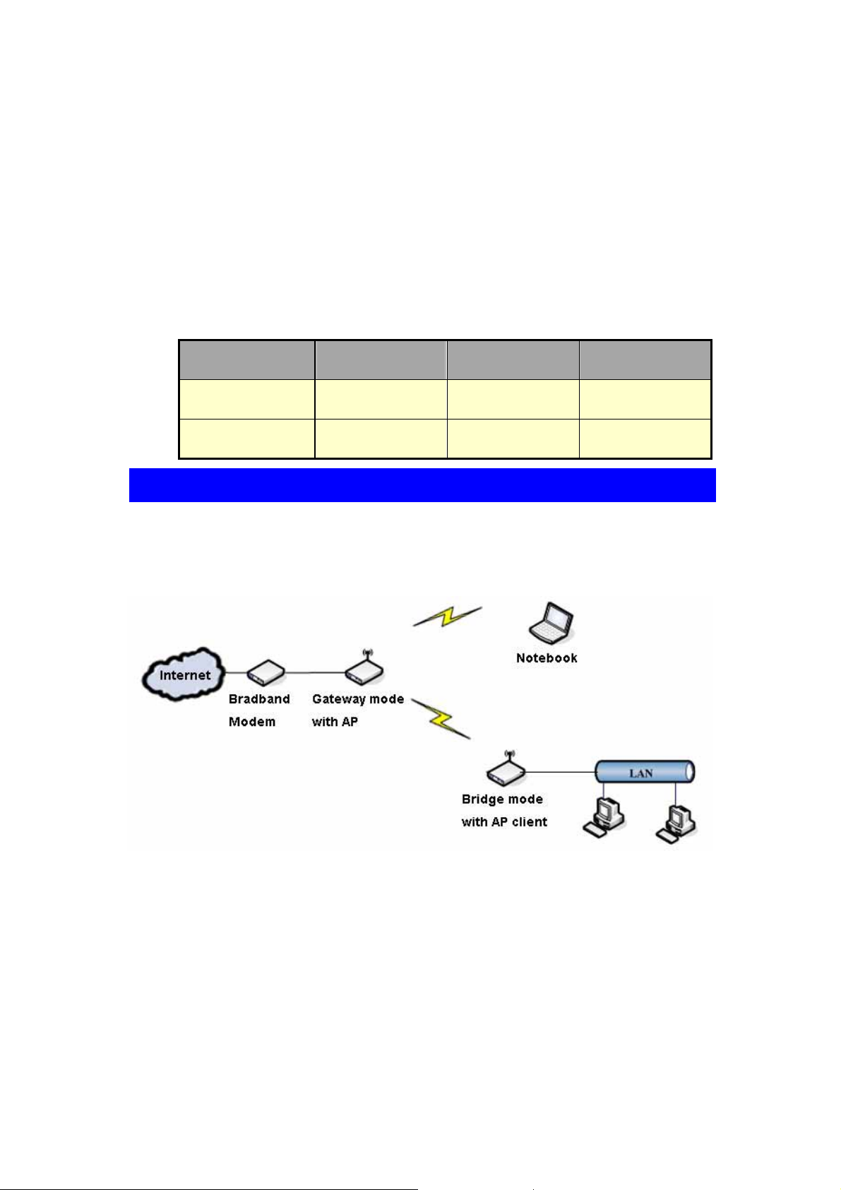
2.3 Topologies of Network Application
Hereafter are some topologies of network application for your reference.
Gateway mode topology:
7
Page 11

Bridge mode topology:
WISP (Wireless ISP) mode topology:
8
Page 12

Ch. 3 Knowing WIFI-ATA
In this chapter, we’ll go through the following topics in order to learn more about what
1FXS Wireless ATA WIFI-ATA can provide, and familiarize ourselves with WIFI-ATA.
The topics are as follows:
z Overview of WIFI-ATA
z Key Features of WIFI-ATA
z Outlook of WIFI-ATA
z Web Configuration Environment
3.1 Overview of WIFI-AT A
The 1FXS Wireless ATA WIFI-ATA user guide provides instructions for administering
the WIFI-ATA. WIFI-ATA is a device converting analog phones into VoIP-ready
devices which support most popular VoIP protocol - SIP (Session Initiation Protocol).
WIFI-ATA can instantly convert your existing PSTN phones into VoIP-ready devices
and enjoy the inexpensive IP telephony services without purchasing extra IP phones. It
features two RJ-45 Ethernet port for sharing the Internet accessibility with your PC
simultaneously while making IP calls.
With built-in NAT function, business persons and/or travelers can use their WIFI-ATA
and computer at the same time with the capability of accessing Internet through
broadband Internet service which hotels provide under single IP architecture,
especially web authentication is required.
9
Page 13

3.2 Key Fea tures of WIFI-ATA
1FXS Wireless ATA WIFI-ATA is a state-of-the-art design featuring several
cutting-edge functions, and it provides users a small box with many things such as
combining data communication and voice communications. The key features are
shown as below.
z Supporting SIP v2 (RFC 3261) Standard
z Auto-Provisioning Function Ensures Easy Configuration with IP PBX
z Supporting Multiple Codecs
z One RJ-45 Port
z 802.11g Wireless AP / AP Client
z Supporting Multiple IP Assignment: PPPoE, DHCP, PPTP, and Static IP
z Supporting VAD (Voice Activity Detection) and CNG (Comfortable Noise
Generation)
z Adaptive Jitter Buffer
z Acoustic Echo Cancellation
z DTMF Tone Generation
10
Page 14
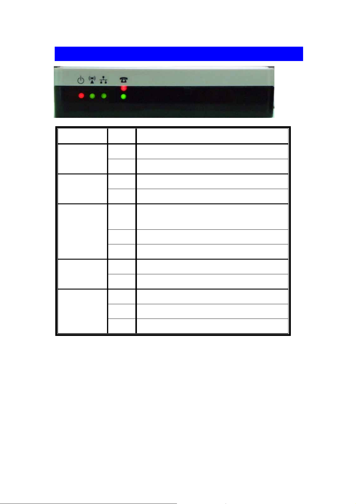
3.3 Outlook of WIFI-A TA
4a
4b
1 2 3
LED Status Description
1
(Power LED)
2
(Wireless LED)
3
(Ethernet LED)
4a
VoIP Status
4b
Phone Status
On WIFI-ATA is receiving power.
Off WIFI-ATA is not receiving power.
Blinking Wireless network is enabled.
Off Wireless network is disabled.
Ethernet port is connected to your network
On
environment.
Blinking Ethernet port is transmitting / receiving data.
Off Ethernet port is disconnected.
On Phone is registered successfully.
Off Phone failed the registration.
On Phone is off-hook.
Blinking Phone has an incoming VoIP call.
Off Phone is on-hook.
11
Page 15

Item Description
Power
Phone
Ethernet
Connection of WIFI-ATA power adaptor
Connection port to analog phone
For connecting to your networking environment
Reset button of WIFI-ATA.
z Press 0~4 sec:reboot the system.
Reset
z Press longer than 5 sec:reset all settings to default.
z When you press the Reset button, the 4a, 4b LED will turn on.
After 5 sec, these LED will be blinking.
Antenna
Wireless antenna.
NOTE:
If configure as gateway mode, do remember to connect Ethernet port to your networking
environment and use wireless for connecting to your PC or laptop computer. Otherwise,
WIFI-ATA might interference the be havior of your LAN environmen t. For more information,
please refer to Chapter 4.
12
Page 16
3.4 Web Configuration Environment
Configuring WIFI-ATA is very simple and as easy as normal networking devices.
Simply use your web browser to do the configuration. Detailed information and
configuration way will be discussed in the following sections.
13
Page 17

Part II AT A Settings
Topics in Part II:
z Ch. 4 Configuring WIFI-ATA
14
Page 18

Ch. 4 Configuring WIFI-ATA
To configure WIFI-ATA, you must connect to the web configuration page first. When
you get a new WIFI-ATA or reset the system to default, the default network mode of
WIFI-ATA is gateway, the default Ethernet WAN IP is 172.1.1.1, and the default
wireless LAN IP is 192.168.1.254, and the DHCP server is on. The default Wireless
SSID is “WIFI-ATA”. You could connect to the LAN side using Wireless adapter cards.
If you connect by wired, please get to the setup page by WAN IP.
If you connect by wireless, please get to the setup page by wireless LAN IP.
Following is the variation of Ethernet port IP in each Operation mode.
Operation Mode Default IP
Ethernet IP 172.1.1.1
Gateway
WLAN IP 192.168.1.254
Bridge Ethernet IP 192.168.1.254
WISP Ethernet IP 192.168.1.254
Client Ethernet IP 172.1.1.1
15
Page 19

Turn on your web browser, ex: Internet Explorer, Netscape or Firefox are all OK, and
enter http://<ip address>. Then, you’ll see the page like below.
In this chapter, this guide will lead you through all the functions of WIFI-ATA, including
the following topics:
z Quickly Setup (Setup Wizard).
z Operation Mode
z TCP/IP Settings
z VoIP Settings
z Wireless
z Firewall
z VPN Setting
z Management
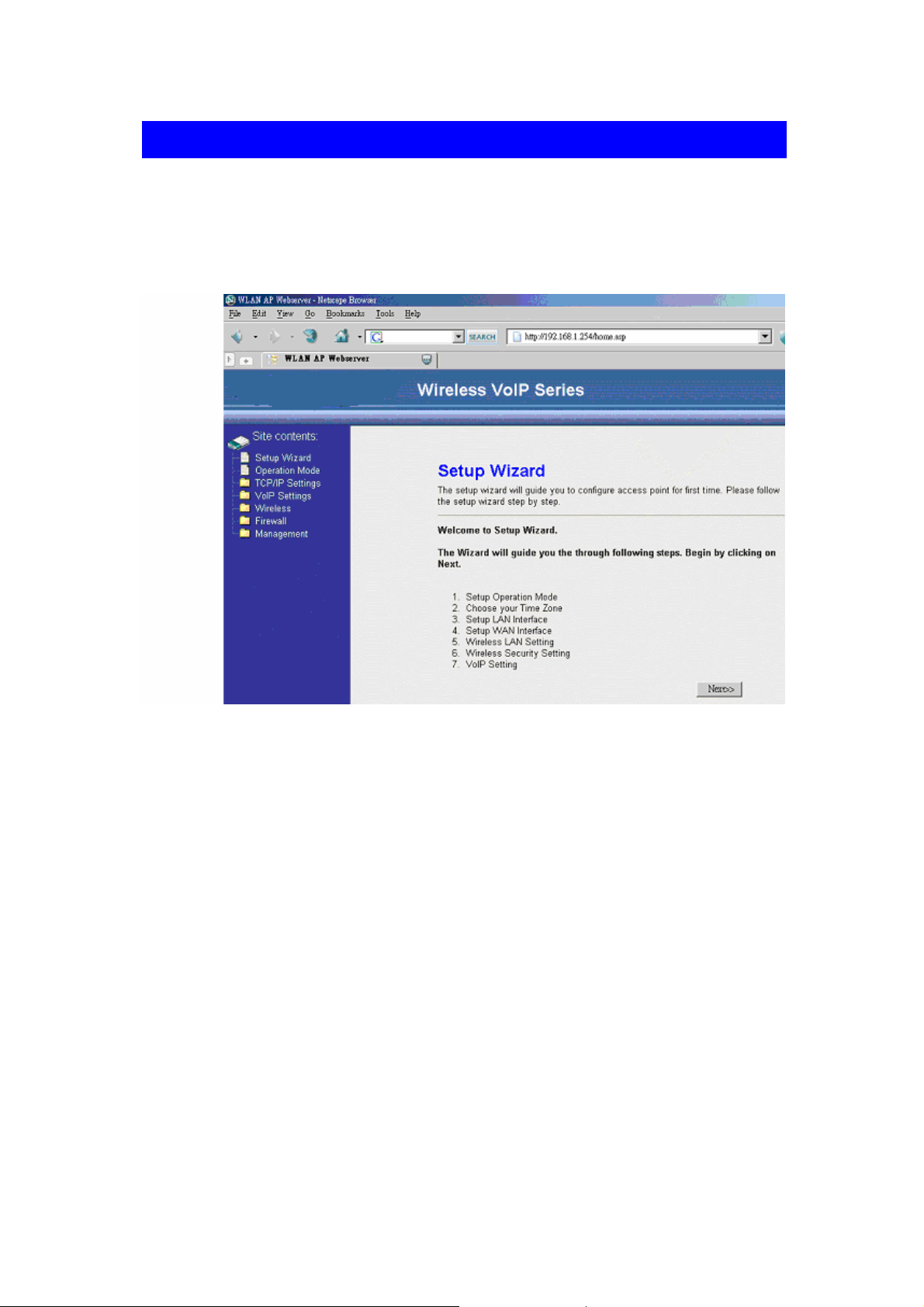
4.1 Quickly Setup (Setup Wizard)
The Setup Wizard is used to first time and quickly configure the WIFI-ATA. It will
configure all the most basically settings about the TCP/IP Network, Wireless Network,
and VoIP SIP account step by step. The following descriptions show the steps to
configure the setup wizard.
Step 1: Select Operation Mode
16
Page 20

The operation modes have been described in section 2.1. Select the most suitable
operation mode according to your network environment. You could click the
miniature to see the topology of each mode. Click “Next>>” to continue.
Gateway topology:
17
Page 21

Step 2: Configure Time Zone
If you enable the NTP client update, select the time zone of your location and the
NTP server to update the system time simultaneity. Click “Next>>” to continue.
Step 3: Configure LAN Network
Configure the static IP address of the LAN interface. This setup may effect
according to the mode you choose. If you choose gateway mode, this step will
change the IP of wireless LAN interface. (Please refer to P.6 table)
If you want to change it to DHCP client, you can change it in the “TCP/IP Settings ->
LAN interface” later. The DHCP server will auto turn on if you configure the
operation mode as Gateway or WISP mode, otherwise it will auto turn off. Click
“Next>>” to continue.
18
Page 22

Step 4: Configure WAN network
If you configure the operation mode as Bridge mode, ignore this step. Configure the
WAN interface as static IP, DHCP client, PPPoE, or PPTP according to your
network environment. If you want to access the webpage from WAN side, enable
Web Server Access on WAN. Click “Next>>” to continue.
Step 5: Configure Wireless Basic Settings
Configure the wireless mode, SSID, and channel. You can click “Show Site Survey”
button to see how many access points are deployed in your environment, and avoid
to use the same SSID and the same channel that are already in used by other AP.
Click “Next>>” to continue.
19
Page 23

Step 6: Configure Wireless Security
Configure the wireless encryption method. It can configure as None, WEP,
WPA(TKIP) PSK, WPA2(AES) PSK and WPA mixed PSK. Click “Next>>” to
continue.
Step 7: Configure VoIP SIP account
Configure the account which is for activating your VoIP service. Fill in the
information you get from ITSP and enter into fields accordingly. Basically, you will
have the VoIP subscription information which are “Register Name,” “Register
Password,” “Proxy Server,” and “Outbound Proxy”. Click “Finish” to finish.
After you click the “Finish” button, please wait some time period to let all settings
come into force. If IP address was changed, you have to re-connect the web server
with the new address.
20
Page 24

4.2 Operation Mode
You could only change the operation mode in this page. The operation mode had
been described in session 2.1. This page is very the same with the setup wizard step
1 page, please reference to session 4.1.
21
Page 25

4.3 TCP/IP Settings
The third feature set of WIFI-ATA is about the TCP/IP networking which contains
“LAN interface” and “WAN interface“. If the operation mode is “Bridge”, only the LAN
interface settings are available. That means LAN/PC port, WAN port, and Wireless
network all use the LAN interface settings in bridge mode. If the operation mode is
“Gateway”, the LAN interface is to configure LAN port and Wireless network; the WAN
interface is to configure WAN port. If the operation mode is “WISP”, the LAN interface
is to configure WAN and LAN port; the WAN interface is to configure the Wireless
network.
4.3.1 LAN Interface
The LAN interface supports “Static IP”, “DHCP Client”, and “DHCP Server”. If you
want to use PPPoE connection, configure the operation mode to “Gateway” and set
the PPPoE account in the WAN Interface page.
The IP Address / Subnet Mask / Default Gate way fields are only available whe n you
use a static IP. It may be provide from the MIS or network provider.
IP Address:Configure the Internet Protocol(IP) address of your local network.
Subnet Mask:It is used to identify the IP subnet network, indicating whether the IP
address can be recognized.
Default Gateway:If you have a gateway device in your local network, you could
configure the gateway’s IP address here.
22
Page 26

The DHCP / DHCP Client Range fields are used to “configure the DHCP Server in
static IP” or “use DHCP Client not static IP”.
DHCP:It can be configure as “Server”, “Client”, or “Disabled”. If you want to use
DHCP client instead of static IP, select “Client”. If you want to enable the DHCP
server, select “Server” and configure the DHCP Client Range. If you want to disable
DHCP server, select “Disabled.”
DHCP Client Range:It is used to configure the IP address range that the DHCP
server will deliver to the DHCP client. So it can only configure when the DHCP server
is enabled. It should be avoid letting your IP address inside the range.
802.1d Spanning Tree:Spanning-Tree Protocol is a link management protocol that
provides path redundancy while preventing undesirable loops in the network. For an
Ethernet network to function properly, only one active path can exist between two
stations. If your network environment contains a loop, enable it.
23
Page 27

Clone MAC Address:If you want to use a specific MAC address instead of the
default MAC address in the LAN port, configure the specific MAC address here.
4.3.2 WAN interface
The WAN interface supports “Static IP”, “DHCP client”, “PPPoE”, and “PPTP”. It will
be unavailable if the operation mode is bridge.
Static IP
Fill in all the information needed, such as IP address, subnet mask, default gateway ,
and the IP address of DNS Server.
DNS(Domain Name Server) is used to map domain names to IP addresses. DNS
maintain central lists of domain name/IP addresses and map the domain names in
your Internet requests to other servers on the Internet until the specified web site is
found.
Note:
Most of cases, you don’t need to take care of the Clone MAC Address field. If you’ve found
other networking devices can not work properly which are connected to the LAN environment
through WIFI-ATA, then you probably need to fill the MAC addre ss into MAC field.
24
Page 28
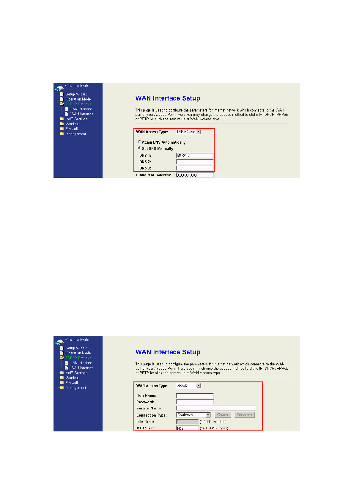
DHCP Client
If WAN Access type chosen as DHCP Client, you can specify the IP address of
DNS server manually or attain from DHCP server.
PPPoE
If you connect your WIFI-ATA directly to your broadband modem, you probably need
to use PPPoE as IP type. Then, you need to enter the User Name and Password
that provided by the ITSP into the fields accordingly. There are three connection
type “Continuous”, “Connect on demand”, and “Manual”.
Continuous:Always connect if the line is available.
Connect on Demand:Only connect when it needs to access internet.
Manual:Manual connect / disconnect by click the “Connect” / “Disconnect” button.
Idle Time:The expiry time of the connection, it is only available when “Connect on
Demand” type is selected.
MTU Size:M aximum transmission Unit, 1412 is the default setting; you may need to
change the MTU for optimal performance with your specific ITSP.
25
Page 29

PPTP
PPTP(Point to Point Tunneling Protocol) is designed as an extension of PPP, it
encapsulates PPP packets into IP datagram for transmission over the Internet or
other public TCP/IP based networks. Please contact with the ITSP for detail
settings.
Others
Enable uPNP:Allow the device to be found and configured automatically by the
system. (Ex. Window XP)
Enable Web Server Access on WAN : Allow others to access the web
configuration page from internet.
IPsec / PPTP / L2PT pass through on VPN connection:Just as the literal
description, they are only available on VPN connection.
26
Page 30

4.4 VoIP Settings
The fourth feature set of WIFI-ATA is about the VoIP related settings which contains
“SIP Basic settings”, “SIP Advanced settings”, “NAT Traversal”, “Call Settings” and
“Dial Settings“.
4.4.1 SIP Basic settings
This is the most important part of WIFI-ATA which is for activating your VoIP service.
Fill in the information you have from ITSP and enter into fields accordingly.
Basically, you will have the VoIP subscription information from ITSP which are
“Register Name”, “Register Password”, “Proxy Server”, and “Outbound Proxy”.
27
Page 31

4.4.2 SIP Advanced settings
SIP Advanced settings contain many other SIP parameters. Some will influence the
voice quality, like “Codec Priority” and “VAD”. Some must collocate with the SIP
server, like “Reg Expire” and “DTMF relay”. And some must collocate with the analog
phone, like “Volume”, “Gain”, “Flash Time”, and “Country”.
Codec Priority:Codec stands for Coder / Decoder which converting your voice into
VoIP packets. Through codec, it can compress the size of your voice and transmitting
on the Internet efficiently. WIFI-ATA supports ITU-T standards, G.711 u-law, G-711
a-law, and G.729. If G.711u-law or G.711 u-law is in use, the voice quality will be very
good. However, you need a plenty of bandwidth. If you find the voice is discontinued
all the time, probably the bandwidth is not enough for support G.711 u-law or a-law. In
such case, please set G.729 as higher priority. If you want to limit to use only specific
codec, just set all codec priorities as the same. For example:Set all codec priorities
as G.729 to use G.729 codec only.
VAD:Voice Activity Detection, is used for saving the bandwidth consumption.
Normally, enabling VAD function can save around 50% traffic. Turn on the VAD
function can effectively solve the bandwidth problem.
Reg Expire :It is about how long the registration is valid, and when the time interval is
expired, WIFI-ATA will resubmit the registration again to the SIP server.
28
Page 32

SIP / Media Port :Configure the local SIP / Media Port. In most cases, you don’t need
to change it.
DTMF Relay:Dial Tone Multi Frequency(DTMF), which is used for sending to the SIP
server in ITSP. Basically, there are three kinds of DTMF type used in VoIP world.
Choose the one your ITSP allow you to use, otherwise you might encounter problems.
SIP / Voice Qos:Quality of Service(QoS), which is used for prioritizing the packets
based on urgency which is set in part of the packet. It’s very important in the VoIP
communication environment since data can always be re -sent so it’s not urg ency at all.
Please note that selecting QoS can not guarantee the voice transmitting will be
expedited all the way. It just can ensure the packets through WIFI-ATA will be filtered
based on QoS type. If your router or other network devices do not support QoS, your
voice packet will be queued somewhere between caller and callee. For more
information about the QoS, please check IETF RFC documentaries about IP ToS.
Handset Volume:The volume you hear from the headset if it’s a VoIP call.
Handset Gain:The volume you talk to the headset if it’s a VoIP call.
Caller ID Mode:It is for selecting which kind of Caller ID system your phone supports.
Flash Time:Configure the flash hook time of your phone.
Country:Configure the country of your phone. In most case, it will be the same as
your current location country.
29
Page 33

4.4.3 NAT Traversal
For sharing the Internet access, routers provide a function called NAT, Network
Address Translation. It helps many computers / network devices can use just one
public IP address. However, it’s not friendly to VoIP devices. NAT Traversal can help
VoIP devices to get through the NAT successfully in order to complete the voice
communication.
WIFI-ATA supports two NAT traversal method “STUN” and “Manual mapping”. STUN
has been described in section 1.3.2 . Manual mapping is to manual configure the
external address and correspond external SIP and RTP port of local SIP and Media
port. It must also configure the port and address mappings in the upper router. The
local SIP and Media port was described in section 4.4.3 .
30
Page 34

4.4.4 Call Settings
This page contains call forward and call waiting settings.
Call Forward is used for the situations which you can’t receive the calls in front of the
phone and you don’t want to miss the calls. By setting the Call Forward, all the
incoming calls will be forwarded to the phone number you set according to the
situation. There are three types of forwarding; “Unconditional Forward,” “Busy
Forward,” and “No Answer Forward.”
“Unconditional Forward” will forward all the incoming calls to the phone number you
set immediately, and make the other two types useless.
“Busy Forward” will be activated if you are on the phone and there’s an incoming call.
In this case, the incoming call will be forwarded to the phone number you set, such a s
your colleague’s or your mobile phone.
“No Answer Forward” means the incoming calls will be forwarded to the phone
number you set if you can not pick up the call in time. The “timeout” period depends
on what you set in the field of “timeout” in this page
The “Call Waiting” function brings you the alternative to take the other phone call
while you are on the phone already. If the Call Waiting has set, you will hear the call
waiting tone during your conversation with someone else.
If you want to pick up this incoming call without stop current conversation, simply
press the flash key your analog phone provides or using the phone hook to simulate
the flash which describe in previous section. Once this call is finished, simply press
the flash key again, you will be able to continue the call on hold.
31
Page 35

4.4.5 Dial Settings
This page contains speed dial and dial plan rule settings.
Speed Dial is a bit like shortcut. Through setting the speed dials, you can call anyone
in the speed dial list simply by dialing “0#” to “9#” instead of entering the complete
phone numbers.
Dial Plan is used for setting the specific kind of dialing pattern. Any number you dial
not matching the pattern won’t work. You can place calls in a short way as the rules
define.
The rules can be only one rule or a set of rules “rule 1|rule 2|rule 3”. Maximum length is 59
words. Each rule should be started with <prefix nu mber> then followed a regular rule.
Fields definition:
Field Description
<01155> prefix number 01155
[2-6] A number between 2~6
[3478] A number 3 or 4 or 7 or 8
X A number 0~9
0,1,2,3,4,5,6,7,8,9 A specific number 0,1,2,3,4,5,6,7,8,9
For example : <01155>[1-9]12xx
<01155> means prefix number 01155, [1-9]12xx is a re gular rule wit h total 5 digits, first
number “1~9”, second number “1”, and thir d number “2 ”.
When you dialed 5 digits that accord with the regular rule (ex : 11267),it will add the
prefix “01155” automatically and dial out.(Really dialed out:0115511267)
32
Page 36

4.4.6 Auto Provision
The function is only applicable when your WIFI-ATA needs to get the configuration file
that is provided by specific service providers, like IP-PBX or UTStarcom. If it is the
case, then you don’t need to configure the SIP related settings. For more information,
please contact with your service provider.
Service Provider:Select the service provider. (only for ZT-9050.) or UTStarcom
(UTSI profile).
Provision Type:Select how to get the configuration file.
TFTP first: Get configuration file from TFTP server. If failed, get configuration file
from HTTP server later.
HTTP first: Get configuration file from HTTP server. If failed, get configuration file
from TFTP server later.
Disable: Do not get configuration file by provision.
TFTP Server Address:The IP address or URL with file path of the TFTP provision
server.
TFTP Server Port:The port of the TFTP provision server.
HTTP Server Address :The IP address or URL with file path of the HTTP provision
server.
HTTP Server Port:The port of the HTTP provision server.
Provision Expiry Time:The system will get configuration file again after expiry
time.
33
Page 37

4.5 Wireless settings
This feature set of WIFI-ATA is about the Wireless related settings which contains
“Wireless Basic settings”, “Wireless Advanced settings”, “Security”, “Access Control”
and “Site Survey“.
4.5.1 Wireless Basic Settings
This page contains the basic settings of the wireless device.
Disable Wireless LAN Interface:Shut down the wireless interface of the device.
Band:The device supports 2.4GHz(B), 2.4GHz(G), a nd 2.4GHz(B+G) mixed modes.
Mode:The radio of the device supports AP and client mode. AP mode:The radio acts
as an Access Point to serves all wireless clie nts to join a wir eless local n etwork. Client
mode:The radio acts as a wireless adapter.
Network Type:This setting is only available at client mode. It supports Infrastru cture
and Ad-hoc. In Infrastructure type, it can only connect to the Access Point. In Ad-hoc
type, it provides a peer-to-peer communication between wireless stations. It can only
connect with other Ad-hoc clients. All the Ad-hoc clients that want to connect together
must use the same SSID.
SSID:The SSID is a unique identifier that wireless networking devices use to
establish and maintain wireless connectivity. Multiple access point/bridges on a
network or sub-network can use the same SSID. SSIDs are case sensitive and can
contain up to 32 alphanumeric characters. Do not include spaces in your SSID.
34
Page 38

Channel Number:
2.4-GHz radio:
Channel No. Frequency (Hz) Country Domain
1 2412 Americas, EMEA, Japan, Taiwan and China
2 2417 Americas, EMEA, Japan, Taiwan and China
3 2422 Americas, EMEA, Japan, Israel, Taiwan and China
4 2427 Americas, EMEA, Japan, Israel, Taiwan and China
5 2432 Americas, EMEA, Japan, Israel, Taiwan and China
6 2437 Americas, EMEA, Japan, Israel, Taiwan and China
7 2442 Americas, EMEA, Japan, Israel, Taiwan and China
8 2447 Americas, EMEA, Japan, Israel, Taiwan and China
9 2452 Americas, EMEA, Japan, Israel, Taiwan and China
10 2457 Americas, EMEA, Japan, Taiwan and China
11 2462 Americas, EMEA, Japan, Taiwan and China
12 2467 EMEA and Japan
13 2472 EMEA and Japan
14 2484 Japan only
EMEA (Europe, the Middle East and Africa).※
When set to “Auto”, the device will find the least-congested channel for use.
Associated Clients:Show the information of active wireless client stations that
connected to the device.
The following table is the available frequencies (in MHz) for the
Enable Mac Clone:It is only available in the AP bridge client mode and the Ethernet
has only linked with one computer. When you enable this function, the device will act
as your computer’s wireless adapter card.
4.5.2 Wireless Advanced Settings
This page contains many wireless performance related parameters. These settings
should not be changed unless you know what effect the changes will have on your
device. The default setting is optimized for the normal operation.
35
Page 39

Authentication Type:The device supports two Authentication Types “Open system”
and “Shared Key”. When you select “Share Key”, you need to setup “WEP” key in
“Security” page (See the next section). The default setting is “Auto”. The wireless
client can associate with the device by using one of the two types.
Fragment Threshold:The fragment threshold determines the size at which packets are
fragmented (sent as several pieces instead of as one block). Use a low setting in areas
where communication is poor or where there is a great deal of radio interference. This
function will help you to improve the network performance.
RTS Threshold:The RTS threshold determines the packet size at which the radio i ssues
a request to send (RTS) before sending the packet. A low RTS Threshold setting can be
useful in areas where many client devices are associating with the device, or in areas
where the clients are far apart and can detect only the d evice and not ea ch othe r. You can
enter a setting ranging from 0 to 2347 bytes.
Beacon Interval:
point beacons in mini-seconds. The default beacon interval is 100.
Data Rate:
The standard IEEE 802.11b/11g supports 1, 2, 5.5, 11 / 6, 9, 12, 18,
The beacon interval is the amount of time between access
24, 36, 48 and 54 Mbps data rates. You can choose the rate that the device
uses for data transmission. The default value is “auto”. The device will use the
highest possible selected transmission rate.
Preamble Type:A long preamble basically gives the receiver more time to process
the preamble. All 802.11 devices support a long preamble. The short preamble is
designed to improve efficiency.
Broadcast SSID:
Broadcasting the SSID will let your wireless clients find the
device automatically. If you are building a public Wireless Network, disable
this function can provide better security. Every wireless stations located within
the coverage of the device must connect this device by manually configure the
SSID in your client settings.
IAPP :
This function will let Wireless Stations roam among a network
environment with multiple devices. Wireless Stations are able to switch from
one device to another as they move between the coverage areas. Users can
have more wireless working range.
36
Page 40

802.11g Protection:Protection is the protocol feature the gives 802.11g compatibility
with older 802.11b equipment. It does slow down 802.11g stations, but not by forcing
them to use slower 802.11b data rates. When an access point activates protection, it
"wraps" faster 802.11g transmissions with a slower, backwards-compatible frame.
The slowdown comes from the backwards-compatibility wrapper, not a reduction in
the data rate of the frame.
4.5.3 Security
This device provides complete wireless security function include WEP, 802.1x, WPA,
WPA2 and WPA2-Mixed in different mode (see the Security Suppo rt Table).
The default security setting of the encryption function is disabled. Choose your
preferred security setting depending on what security function you need.
WEP Encryption Setting:Wired Equivalent Privacy (WEP) is implemented in this device
to prevent unauthorized access to your wireless network. The WEP setting must be as
same as each client in your wirel ess net work. For mo re secure d ata transmissi on, you can
change encryption type to “WEP” and click the “Set WEP Key” button to open the
“Wireless WEP Key setup” page.
37
Page 41

When you decide to use the WEP encryption to secure your WLAN, please refer to the
following setting of the WEP encryption:
z 64-bit WEP Encryption:64-bit WEP keys are as same as the encryption method of
40-bit WEP. You can input 10 hexadecimal digits (0~9, a~f or A~F) or 5 ACSII
chars.
z 128-bit WEP Encryption:128-bit WEP keys are as same as the encryption method
of 104-bit WEP. You can input 26 hexadecimal digits (0~9, a~f or A ~F) or 10 ACSII
chars.
The Default Tx Key field decides which of the four keys you want to use in your
WLAN environment.
38
Page 42

WEP Encryption with 802.1x Setting:The device supports external RADIUS Server that
can secure networks against unauthor ized access. If you use the WEP encryption, you
can also use the RADIUS server to check the admission of the users. By this way every
user must use a valid account before accessing the Wireless LAN and requires a RA DIUS
or other authentication server on the netwo rk. An example is sh own as followi ng.
You should choose WEP 64 or 128 bit encryption to fit with your network envi ronment first.
Then add user accounts and the target device to the RADIUS server. In the device , you
need to specify the IP address、Password (Shared Secret) and Port number of the target
RADIUS server.
WPA / WPA2 / WPA2 Mixed Encryption Setting:WPA feature provides a high level of
assurance for end-users and administrators that their data will remain private and access
to their network restricted to authorized users. You can choose the WPA encryption and
select the Authentication Mode.
39
Page 43

WPA Authentication Mode:This device supports two WPA modes. For personal user,
you can use the Pre-shared Key to enhance your security setting. This mod e requires only
an access point and client station that supports WPA-PSK. For Enterprise, authentication
is achieved via WPA RADIUS Server. You need a RADIUS or other authentication server
on the network.
WPA / WPA2 Cipher Suite:Choose the cipher type of the WPA / WPA2 encryption.
Enterprise (RADIUS):When WPA Authentication mode is Enterprise (RADIUS), you
have to add user accounts and the target device to the RADIUS Server. In the devi ce , you
need to specify the IP address、Password (Shared Secret) and Port number of the target
RADIUS server.
Pre-Share Key:This mode requires only an access point and clie n t sta t io n tha t supp orts
WPA-PSK. The WPA-PSK settings include Key Format, Length and Value. They must be
as same as each wireless client in your wireless network. When Key format is Passphrase,
the key value should have 8~63 ACSII chars. When Key format is Hex, the key value
should have 64 hexadecimal digits (0~9, a~f or A~F).
40
Page 44

4.5.4 Access Control
Access Control is used to manage whose clients can connect to this Access Point.
Allowed Listed:Only those clients whose wireless MAC addresses are in the list will
be able to connect to this Access Point.
Deny Listed:These wireless clients on the list will not be able to connect to this
Access Point.
4.5.5 Site Survey
Site Survey is used to show how many wireless access points are deployed in this
environment. If current wireless mode is client mode, you could choose one access
point and click “connect” button to connect to this specific AP.
41
Page 45
4.6 Firewall settings
This feature set of WIFI-ATA is about firewall functions which contain “Port Filtering”,
“IP Filtering”, “MAC Filtering”, “Port Forwarding”, “URL Filtering”, and “DMZ” These
are all only available in Gateway mode or WISP mode.
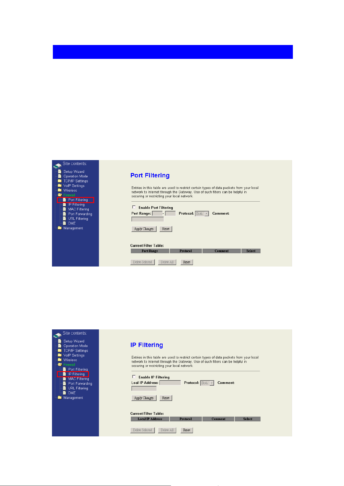
4.6.1 Port Filtering
When you enable the Port Filtering function, you can specify a single port or port
ranges in filter table. Once the source port of outgoing packets match the port
definition or within the port ranges in the table, they will be blocked by the firewall.
4.6.2 IP Filtering
When you enable the IP Filtering function, you can specify local IP Addres ses in filter table.
Once the source IP address of outgoing packets match the IP address definition in the
table, they will be blocked by the firewall.
42
Page 46

4.6.3 MAC Filtering
When you enable the MAC Filtering function, you can specify the MAC Addresses in
filter table. Once the source MAC Address of outgoing packets matches the MAC
Address definition in the table, they will be blocked by the firewall.
4.6.4 Port Forwarding
This function allows you to automatically redirect common network services to a
specific machine behind the NAT firewall. These settings are only necessary if you
wish to host some sort of server like a web server or mail server on the private local
network behind the device's NAT firewall.
43
Page 47

4.6.5 URL Filtering
When you enable the URL Filtering function, you can specify some HTTP URLs in
filter table. If the PCs in the local private network want to access these webpage in the
filter table, it will be blocked by the firewall.
4.6.6 DMZ
A Demilitarized Zone is used to provide Internet services without sacrificing
unauthorized access to its local private network. Typically, the DMZ host contains
devices accessible to Internet traffic, such as Web (HTTP) servers, FTP servers,
SMTP (e-mail) servers and DNS servers. So that all inbound packets will be
redirected to the computer you set. It also is useful while you run some applications
(ex. Internet game) that use uncertain incoming ports.
44
Page 48

4.7 Management
This feature set of WIFI-ATA is about the system related information and
management settings which contains “Status”, “Statistics”, “DDNS”, “Time Zone
Setting”, “Log”, “Upgrade Firmware”, “Save/Reload Settings” and “Password“.
4.7.1 Access Point Status
This page shows the information about the firmware version, current wireless status,
current network settings, and VoIP version.
4.7.2 Statistics
This page statistics how many packets are sent or received in each network device.
Page 49

4.7.3 Dynamic DNS Setting
Dynamic DNS is a service, that provides you with a valid, unchanging, internet
domain name (an URL) to go with that (possibly ever changing) IP-address. If you are
not using a fixed IP, you might have to configure the DDNS to let the internet domain
name of this device can connect to this device correctly.
4.7.4 Time Zone Setting
This page is used to configure current system time. And you could enable the NTP to
adjust the system time with NTP server synchronously.
Page 50

4.7.5 System log
This page shows the system event logs if you enable it. If you want to put these logs
to remote log server to restore these logs, enable the remote log and fill the remote
log server address.
4.7.6 Upgrade Firmware
This page is used to upgrade firmware. Be sure that you had got the correct model
firmware, or you might damage the system.
Page 51

4.7.7 Save / Reload Settings
You could restore current device settings as a config file to your computer, upload this
config file to another device, and reset all settings to default value in this page.
4.7.8 Password Setup
This page is used to configure the user name and password for login to the webpage.
The default user name and password are empty. For more security, you could
configure
48
Page 52

Part III Illustrations
Topics in Part III:
z Ch. 5 FAQ & Troubleshooting
49
Page 53

Ch. 5 FAQ & Troubleshooting
This following highlights some potential problems and the corresponding
reactions.
5.1 How can I make a phone call?
Make sure you have done all the settings of your WIFI-ATA, and the Re gister LE D
is on.
Just pick up the phone and dial the number and ending with the pound key “#”,
then you can talk the counter part you’re party once he/she answers the call.
5.2 How can I pick up the call w aiting while I’m on the phone?
If you enable this function, it means the Call Waiting function has been turned on.
When there’s a new incoming call while you are on the phone with the other
person, you can press the Flash button to switch to the new call.
Once you’ve switched the phone conversation to the 2nd person, the first person
you talked with will be put on-hold. You can press the Flash button again to switch
back to the first one.
50
Page 54

5.3 How can I mak e a 3-way conference call?
Making 3-way conference call is pretty similar to making phone call; just follow the
steps below, and your 3-way conference will be there for you.
1. Make a phone call to the first phone number.
2. After the call is established, press the Flash button. You will hear the Dial tone,
and then make the other phone call to the second phone number.
3. When the second call is established, press the Flash button again. Then, all
the 3 parties can enjoy the conference call.
5.4 How can I transfer a call to others?
For using “Blind Transfer” function, you just need to dial "*"+ "1" to hold the
current call, and then dial the extension number where you like the call to be
transferred.
For using “Ringing Transfer” function, you just need to press the Flash to hold the
current call, and then dial the extension number where you like the call to be
transferred. After hearing the ring back tone, press pound key “#” to transfer.
For using “Consultant Transfer” function, you just need to press the Flash to hold
the current call, and then dial the extension number where you like the call to be
transferred. After the conversation has established, press pound key “#” to
transfer.
5.5 Why can’t I login to the WIFI-ATA?
Make sure you set the correct IP address of WIFI-ATA. If you’ve confirmed the
WAN IP address of WIFI-ATA is correct but you still can not access the webpage
of WIFI-ATA from the WAN side, you probably did not enable “Web Server Access
on WAN”. In this situation, you can only access the webpage from the LAN side.
5.6 Why can’t I access the Internet?
Please check which network mode, “Bridge Mode”, “Gateway Mode”, or “WISP
mode” your WIFI-ATA is set and check if the Ethernet ports are used correctly.
Page 55

5.7 Why can’t I make V oIP phone calls to others?
Please check the “VoIP Basic Settings” webpage, and compared if all the
information your ITSP gave you has been entered into WIFI-ATA correctly.
5.8 WIFI-A T A doesn ’t respond correctly to key press sometimes.
If the behavior of WIFI-ATA is not so properly especially you need to dial the number after
the phone connection has established, su ch as dialing the extensi on numbers, the DTMF
setting is probably wrong. Please enter the “VoIP Advanced Settings” webp age, and check
the DTMF settings. The setting should be absolutely the same as what ITSP told you;
otherwise, you WIFI-ATA might have some troubles whil e you need to dial again d uring
the phone calls.
52
 Loading...