


9999100
NOTICE:
After taking pictures using the Exposure
Compensation feature, be sure to return
the exposure compensation dial to the 0
position.
The exposure compensation feature is
available during AE locked operation.
The width of the exposure compensation
step can be changed.
The maximum amount of the compensation
can be set either at ±3 or ±5.
9.0 Advanced 645DF+ Camera Functions
9.1 Exposure Compensation
In situations providing extreme high contrast, the resulting photograph may
be under or overexposed. When this occurs, use the Exposure Compensation
function. Exposure Compensation can also be used when you want to
intentionally create overexposed or underexposed pictures.
N.B. Creating an under or overexposed image can also be eectivity achieved
with the High Dynamic Range Tool and Exposure Tool in Capture One.
The exposure compensation dial icon:
C3
C2
C1
A
Exposure mode Exposure compensation display
P
Av
Tv
M
X
Program AE
Aperture Value Priority
Time Value Priority
Manual Mode
Sync Mode Not displayed
X
CF
M
Tv
Av
P
The set value is displayed
The dierence between the metered
value and the set
Exposure value is displayed
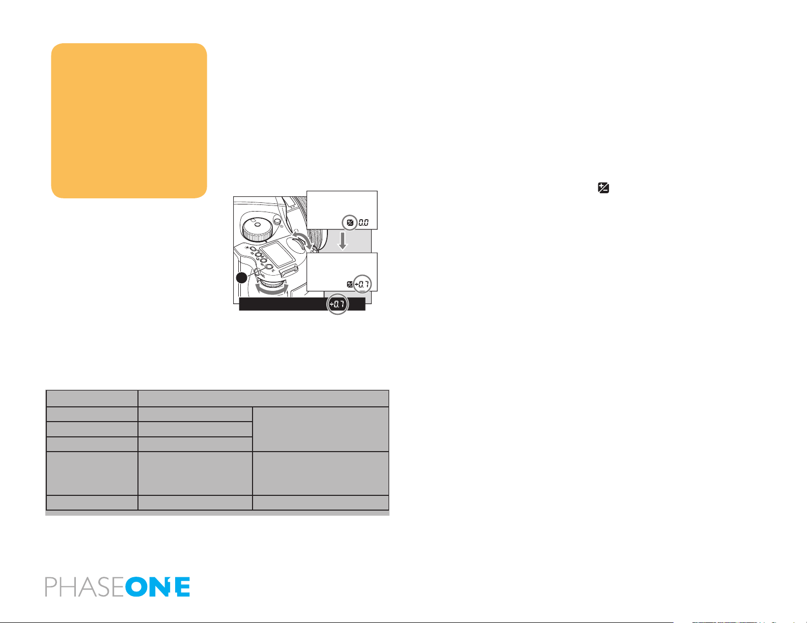
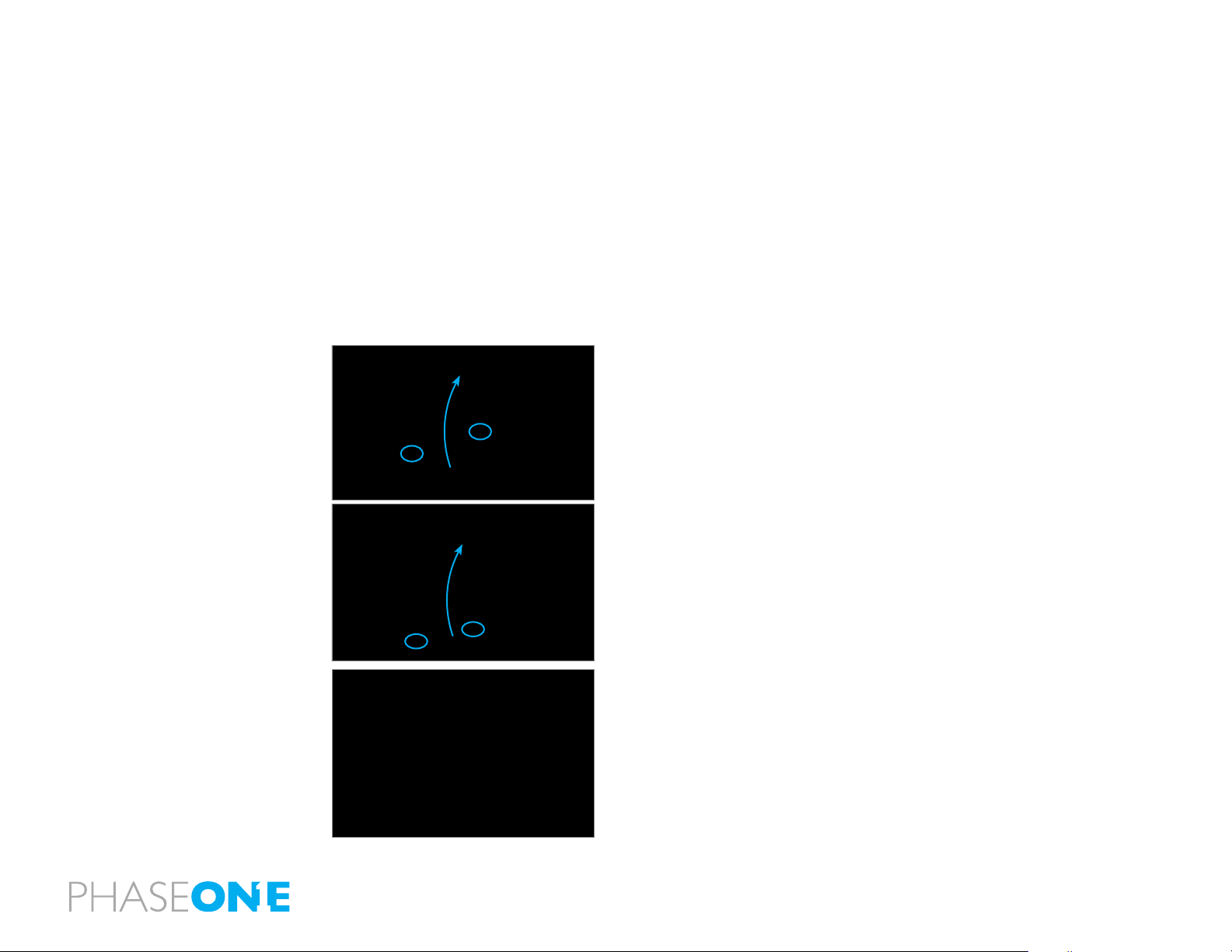
1. Press the Exposure Compensation button [A] so that icon appears on the
camera’s top LCD. When the front or rear dial is turned counter-clockwise, the
exposure is increased and when it is turned clockwise, it is decreased. The
exposure compensation value can be checked on the external LCD or LCD
inside the viewnder.
2. After taking the pictures, press the Exposure Compensation button
[A] again to return the exposure compensation value to 0. The exposure
compensation value mark on the external LCD is cleared and the exposure
compensation function is released.
9.2 AE Lock
X
CF
M
C3
Tv
C2
Av
C1
P
AE lock function is useful in a number of shooting scenarios but is particularly
useful when capturing panoramic images where a consistent exposure is
needed to seamlessly stick images together in post production.
NOTICE:
[ ] in the viewnder LCD blinks to indicate
the exposure is locked, when you continue
to take the next picture in the AE lock mode.
If you turn the shutter release mode selector
lever to the L (power OFF) position, or after
elapse of one hour, the AE lock mode will
automatically be cancelled.
In the Manual M exposure mode, you cannot
use the AE lock function.
When the dierence between the metered
value and the set value is displayed, press
the AEL button [A] for approximately one
second, and one-push shift function will be
activated and the camera will automatically
adjust the shutter speed.
A
The AEL button will lock the Auto-exposure value as the photo is being
recomposed.
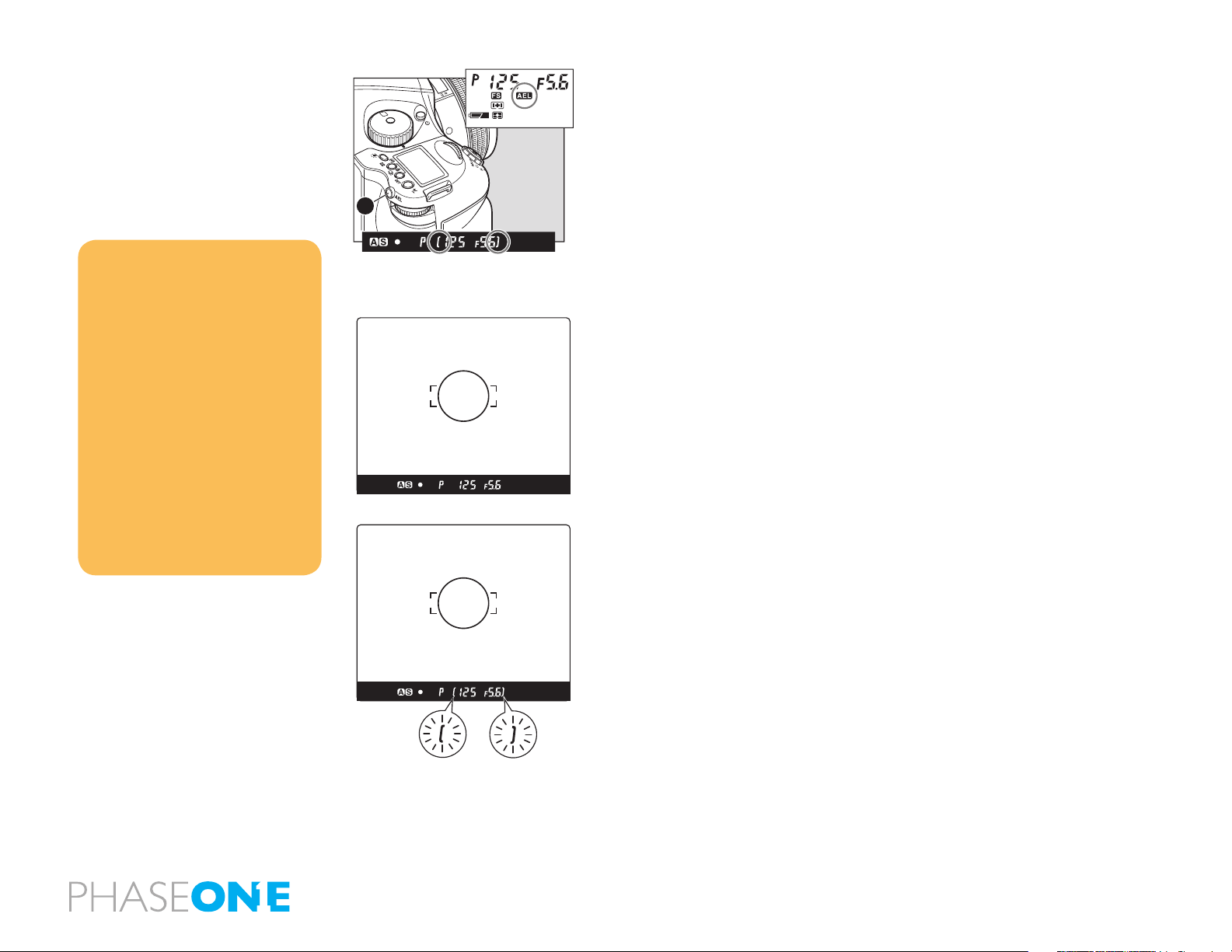
1. Turn the shutter release mode selector lever to S or C.
2. Turn the exposure mode setting dial and select P, Av or Tv.
3. Focus on the subject for metering exposure, and press the AEL button on
the rear of the grip. [ ] Will appear on the viewnder LCD, indicating that
the exposure value is locked.
4. Slide the camera to recompose the shot, and take the picture.
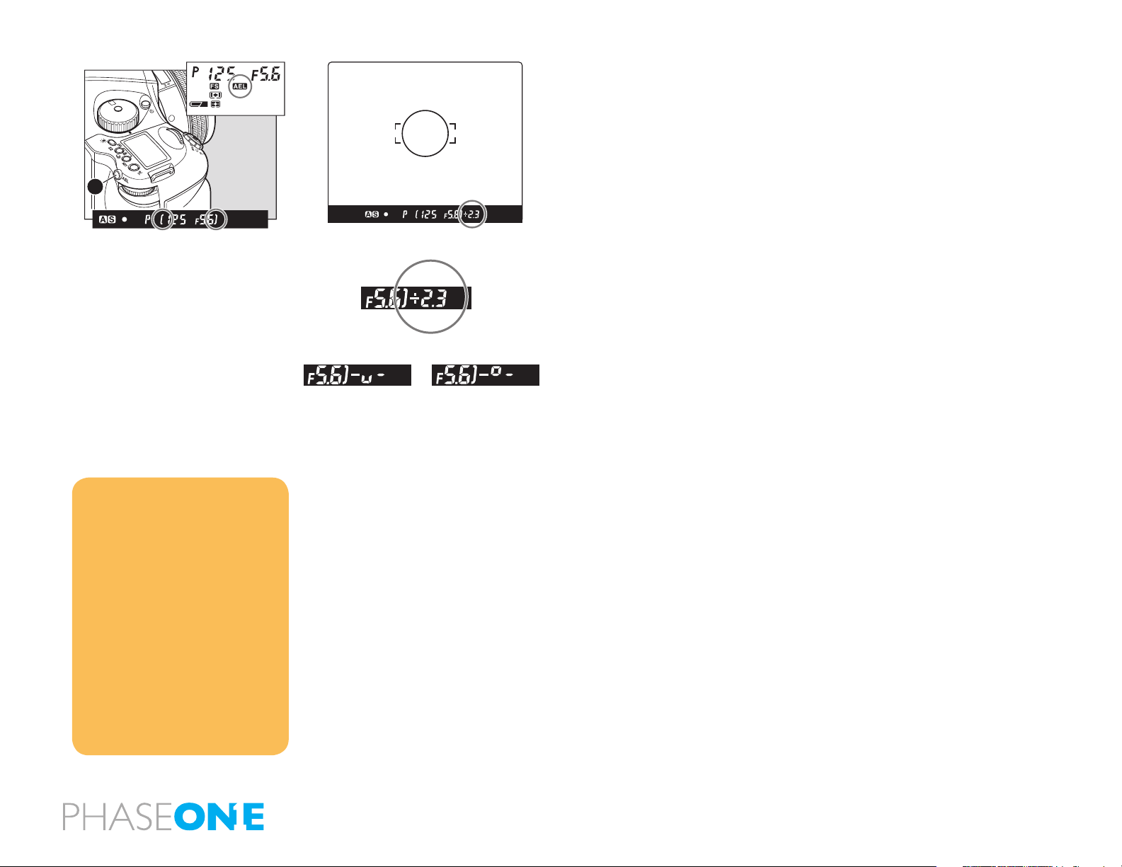
When you press and hold AEL button the over/under exposure value will be
shown to the far right in the viewnder LCD.
101
9.3 Metered-Value Dierence Indicator
X
CF
M
C3
Tv
C2
Av
C1
P
A
Keep pressing the AEL button [A] and the dierence between the metered
exposure value and the exposure of the new composition will be displayed
on the viewnder LCD. This function can be used to see if an object of very
dierent brightness levels can be properly photographed.
If the dierence between the set value and the metered value exceeds
6EV, the viewnder LCD blinks “– u –” for underexposure and “– o – ” for
overexposure.
NOTICE:
The way to cancel the AE lock can be
changed. C-11 AEL function lock/unlock mode
[AEL]
Half-pressing of he shutter release button
can activate the AE lock mode. C-10 Release
button [HALF]
The assignment of the AEL button and AFL
button can be swapped by using C-09 AEL &
AFL button [AEFL]
Exposure compensation and autobracketing function can be used when the
camera is in the AE lock mode in normal
operation or with the mirror locked up.
By turning the front or rear dial in the AE lock mode, you can change the
aperture and shutter speed value without changing the exposure value that
is set when entered into AE lock mode.
In the P mode (Program AE) mode, turning either the front or rear dial shifts
the program to PH and PL. When in Av (Aperture priority AE) or Tv Shutter
priority AE), turning one of the dials changes both the aperture and shutter
speed values.
102
NOTICE:
When you want to cancel the autobracketing mode, turn the rear dial to
change “On” to “OF”
9.4 Auto Bracketing
X
CF
M
C3
Tv
C2
Av
C1
P
Auto Bracketing can be used when it is dicult to determine your exposure
compensation value. This function automatically captures dierent exposure
variations in succession. The bracketing margin can be selected as desired
for shooting in Auto Bracketing mode.
NOTICE:
After multiple turns, the mark [RP] will appear
in the main LCD.
Repeat turning will lead to a countdown
being displayed on the main LCD and after
taking a photo the camera will return to Auto
Bracketing mode.
The setting for the Auto Bracketing will
be stored by pressing any other button or
leaving the camera for 5 seconds.
A
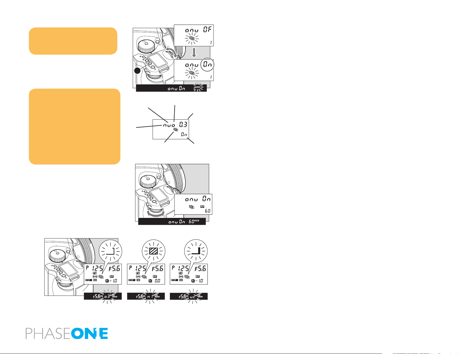
Underexposure
Standard
Auto Bracketing Icon
X
CF
M
C3
Tv
C2
Av
C1
P
Overexposure
Bracketing Margin
Setting selection
1. Turn the Shutter Release Mode Lever to the S or C position.
When set at the S position, you can shoot a single frame with each full press
of the Shutter Release button. In the C mode, the camera takes a series of
three frames successively with one press of the shutter release button.
2. Turn on Auto Bracketing by pressing the Auto Bracketing button[A] for
approximately one second. The Auto Bracketing icon will blink on the top
LCD panel. Turn the front dial (before this indicator times out) and change
OF on the display to On.
3. When the shutter button is pressed in Auto Bracketing mode, the auto
bracketing mark will blink on the LCD inside the viewnder. The bracket step
width is displayed and the Auto Bracketing icon will also blink.
4. To deactivate the bracketing function, press the Auto Bracketing set
button[A], turn the rear dial, set auto bracketing mode to OF, and release.
Then press the Auto Bracketing set button [A] or half-press the shutter button
to return to the normal display mode.
X
CF
M
C3
Tv
C2
Av
C1
P
103
AE Settings Under Auto-bracketing Mode
Exposure Mode Setting
P
Av
Tv
M
X
Program AE Shutter speed varies
Aperture Priority AE Shutter speed varies
Shutter Priority AE Aperture varies
Manual Mode Shutter speed varies
X-sync mode No setting
Single-Frame Mode (S)
Press the shutter release button for each shot. The camera meters adequate
exposure value for each shot and performs Auto Bracketing. The camera
stays in the Auto Bracketing mode until you cancel the Auto Bracketing
mode manually.
Continuous Mode (C)
By pressing the shutter release button once, the camera takes 3 shots in
series. With each full press of the shutter release button, the camera repeats
auto-bracketing. The standard (normal) exposure value will be xed when
you take the rst frame.
Cancelling Auto Bracketing
When you want to cancel the auto-bracketing mode, turn the rear dial to
change “On” to “OF”.
NOTICE:
When exposure compensation is initiated
by pressing the exposure compensation
button, shooting in Auto Bracketing mode
is possible using the exposure value to
which the exposure compensation value
has been added.
104
NOTICE:
Auto bracketing exposures can be made
when the auto bracketing mode is set
before taking photos with mirror up.
After 10 seconds, mirror up photography
will be cancelled
The mirror will return to the original
position if the lens is removed from the
camera body
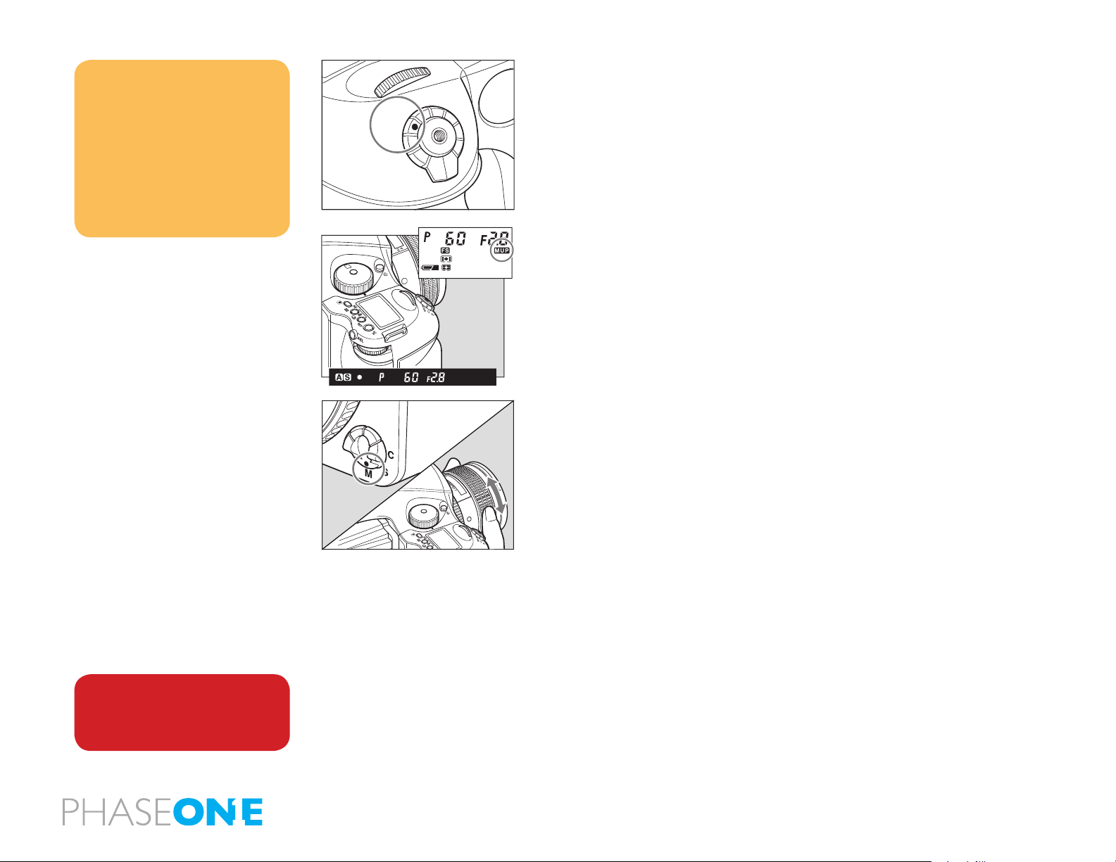
9.5 Taking Photos with the Mirror Up
This function prevents mirror-caused vibrations which may blur an image
when shutter speed is slow. A electromagnetic Cable Release RE401 (optional)
M.UP
C
S
L
is recommended to use with the mirror-up function.
1. Set the drive dial to M.UP.
2. Select S (single focus mode) by turning the focus mode selector lever.
3. Turn the exposure dial to P, Av or Tv exposure mode.
X
CF
M
C3
Tv
C2
Av
C1
P
4. Ensure the subject is in focus and that composition and exposure have
been determined.
5. The mirror moves up when the shutter release button is fully pressed.
6. Press the shutter release button again to take pictures.
In the Manual Mode
Follow steps 1 through 3 of the above auto focusing steps and continue with
the steps below.
2.25
0.7
25
22
0.8
ft
m
1-3 (reference steps 1-3 in the Mirror Up Autofocus method)
WARNING:
DO NOT point the lens at the sun during the
Mirror Up mode. The sun’s intense light can
scorch and damage the shutter curtain.
4. Set the focus mode selector lever to M (manual focus mode). Turn the
lens-focusing ring to focus.
5. Determine the exposure, focusing and frame structure by pressing the
shutter release button halfway while looking into the viewnder.
6. Lock the mirror up by pressing the shutter release button.
7. Press the shutter release button again to take pictures.
105
9.6 Mirror Up Delay
X
CF
M
C3
Tv
C2
Av
C1
P
X
CF
M
C3
Tv
C2
Av
C1
P
22
11
4
4
11
22
5
20
0
AF
MF
1:28
80mm
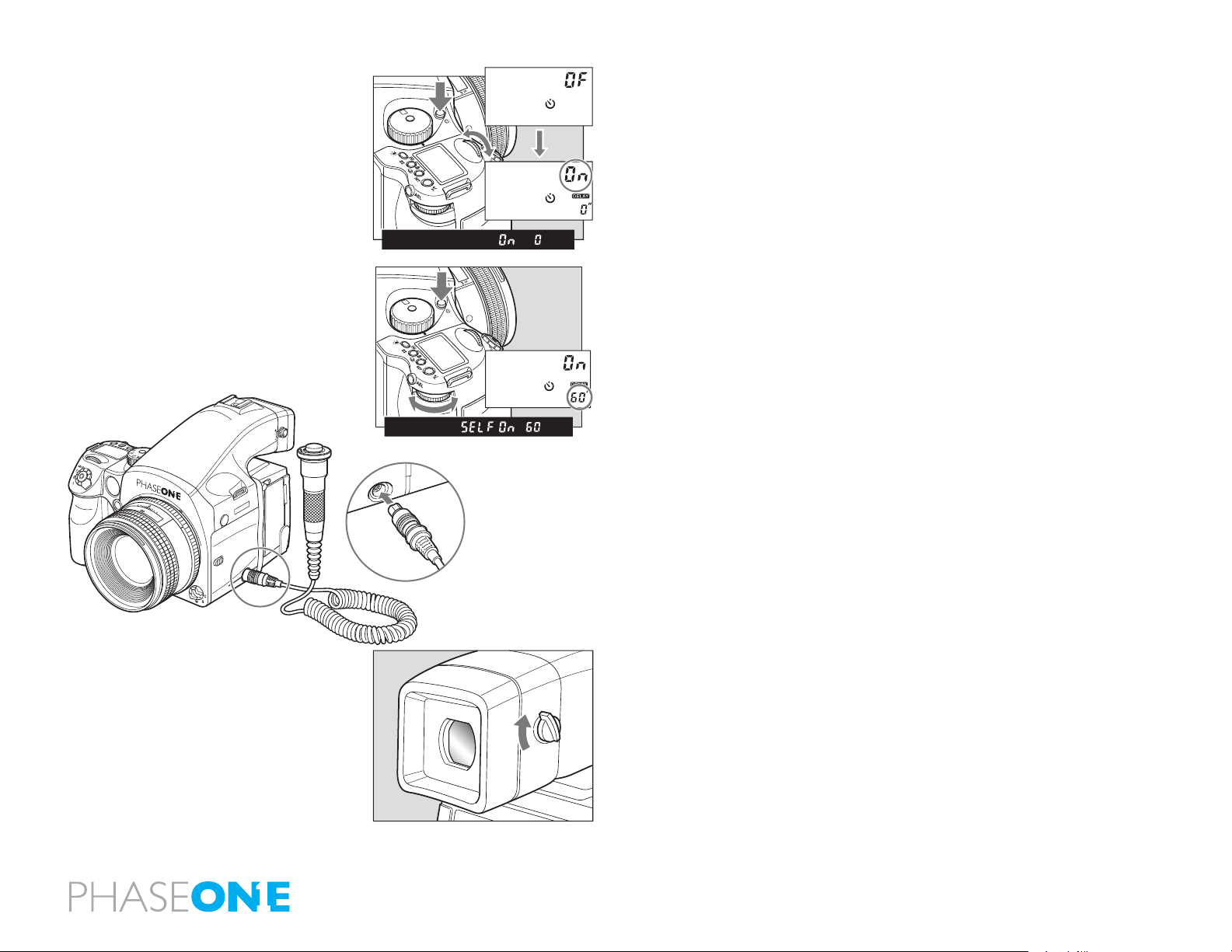
To change from the Self-timer to the Mirror Up setting, press the shutter
button so the mirror goes into the upright position. Once the set time
has expired the shutter will release, and the mirror will return to the lower
position. Separately purchased electronic cable release RE401 can be used
to eliminate camera shake.
When using autofocus the operational method is the same as 1 to 3 when
using M.UP and autofocus.
1-3 (reference steps 1-3 in the Mirror Up Autofocus method).
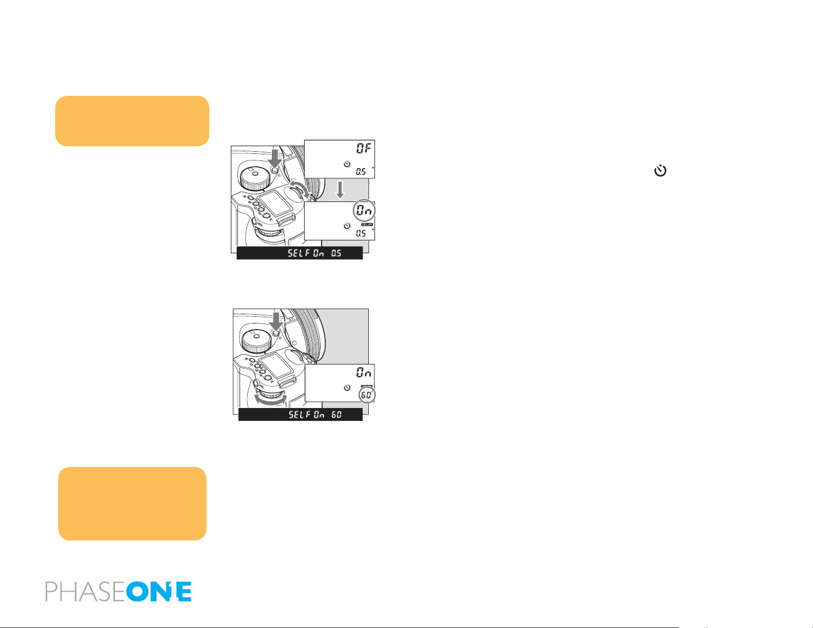
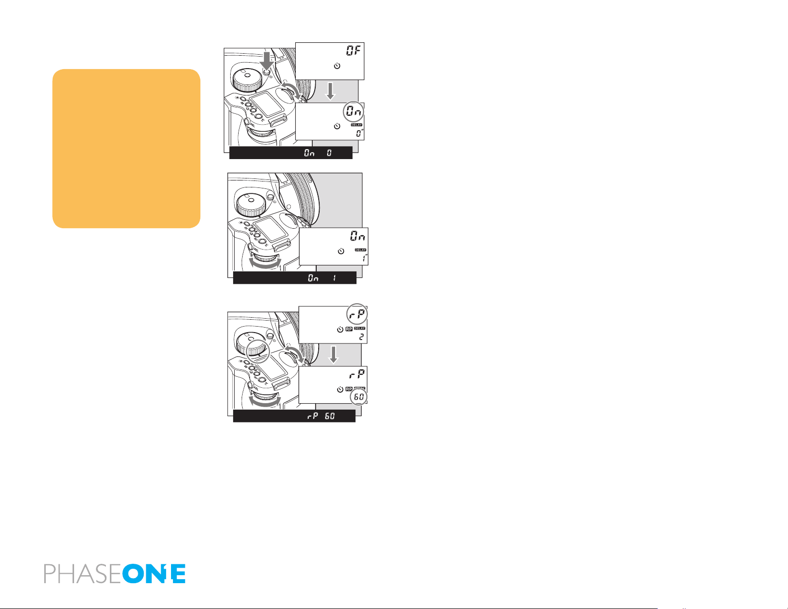
4. Press the Self-timer button and turn the front dial to ON.
5. Turn the rear dial to select the time needed. 0.5/1 seconds to 10 seconds
allows for increases by the second, 10 to 90 seconds increases by 10 seconds
per turn. For 2 to 10 minutes the value by the minute and 10 to 60 minutes
increases by 10 minutes per turn.
6. Line up the photograph through the viewnder and half press the shutter
button to ensure the focus and framing is correct.
7. Full-press the shutter button and the mirror will go to the upper position,
then after the set time the shutter will release and the mirror will return to
the lower position.
Electronic Shutter Release Contact
For Mirror Up, long exposure, or slow shutter shooting, use the magnetic
cable release RE401 or the remote control RS402. The assisting release
contact is to insert the cable.
Eyepiece Shutter
Close the eyepiece shutter when there is a strong light source behind the
camera.
106
NOTICE:
As the camera is electronically controlled
even during exposures, it is recommended
to replace batteries before bulb exposure.
NOTICE:
Using “tIME” (Time) setting, the shutter will
open and close according to the number of
times you press it.
“tIME” (Time) photography is electronically
controlled so it is possible that the batteries
will drain quickly. In the case, please replace
the batteries with new ones.
9.7 Bulb Mode & Long Exposure
C2
C1
C3
P
CF
Av
X
M
Tv
v
M
X
T
Av
CF
P
C3
C1
C2
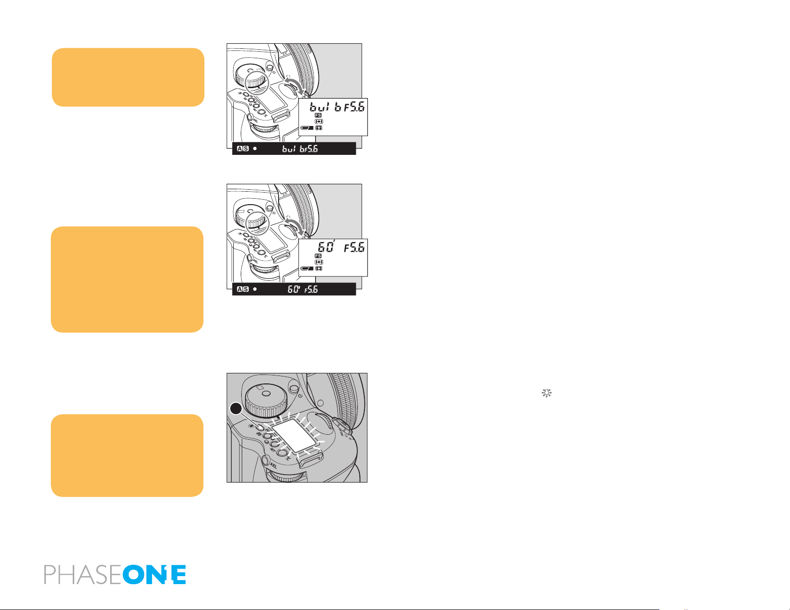
To make an exposure longer than 30 seconds, adjust the shutter speed
to “B” (bulb). In order to prevent camera shake, use the RE401 or RS402
electromagnetic shutter release and tripod.
1. Turn the exposure mode dial to M (manual mode).
2. Turn the front dial to select ‘bulb’, then turn the rear dial to set the aperture.
3. Determine the composition, focus and then take the picture. The shutter
remains open as long as the shutter release button is pressed.
Setting Long Exposures
When photographing under normal conditions, the shutter speed can be
adjusted for longer exposures.
Turn the front dial for shooting time settings. New time settings include 1,
bulb, tine(Time), 2, 4, 8, 15, 30, 60.
NOTICE:
When releasing the shutter, or pressing the
backlight button [A]
while the backlight is on, the backlight will
go OFF.
Choose the time of display light. C-03
Sleeptimer [HOLd]
X
CF
M
C3
Tv
C2
Av
C1
P
A
9.8 Camera Display Light
Press the backlight button[A] to illuminate the top display to see it at night
or in dark places.
The backlight will go on for approximately 20 seconds and turn o unless it
is pressed again.
The backlight will be lit for approximately another 10 seconds when
operating the camera.
107

NOTICE:
The setting will be stored after one second.
Dial lock can not be set when the exposure
mode is P (program AE).
Even while dial lock is set, the front dial or
rear dial can still be used to perform the
various settings. (Dial lock is temporarily
released.)
9.9 Front/Rear Dial Lock Mechanisms
CF
C3
X
C2
M
C1
Tv
Av
P
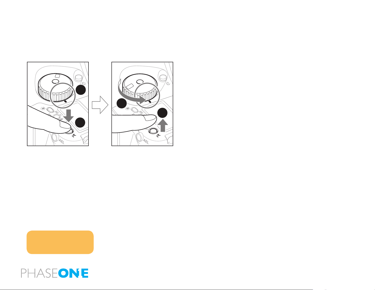
When the Electronic Dial Lock is On, all currently set values in Av (Aperture
Priority AE), Tv (Shutter Priority AE) and M (Manual mode) cannot be adjusted
with the front or rear dials. This prevents accidental change of shutter speed
or aperture values.
X
CF
M
C3
Tv
C2
Av
C1
P
Press down the two lock buttons [A] and [B] at the same time for approximately
one second, until the On indicator blinks.
A
B
To release the mode, hold down the same buttons until OF blinks.
is displayed on the main LCD to indicate that operation of the front and
rear dials is locked.
When the dial lock is ON, the shutter speed and aperture will not change
CF
C3
X
C2
M
C1
Tv
Av
P
even if you turn the front or rear dial.
When you activate the electronic dial lock, and then operate the electronic
dial, the dial lock indicator on the main panel blinks for three seconds to
show that the electronic dial lock is functioning.
108
Notice:
To release the self timer while it is
operating, turn o the power (by setting
the drive dial to L)
9.10 Self-Timer Mode
The default setting for the Self-Timer mode to release the shutter is 10
seconds after the shutter release button is pressed. The self timer lamp
ashes slowly for the rst 7 seconds, and then ashes quickly for the last 3
seconds before the shutter is released. This function can be used to avoid
camera shake, to take group photos or for self-portraiture.
1. Mount the camera on a tripod.
X
CF
M
C3
Tv
C2
Av
C1
P
2. Switch the shutter release mode selector to the (self timer mode).
3. Turn the front dial, and set the self-timer mode to ON.
4. Check the view by looking through the viewnder. Make sure that the
focus is correct, press the shutter release button and the shutter will be
released after 10 seconds.
Changing the Self-Timer Duration
Notice:
In the Self-timer setting, put the drive
dial to M.UP (mirror up) mode. Should
you wish to operate with mirror up and
delay, simply switch the drive dial to
M.UP(mirror up) mode in the Self-timer
setting.
X
CF
M
C3
Tv
C2
Av
C1
P
1. Press the Self-Timer button to activate this function.
2. Turn the rear dial to change the duration of the Self-Timer. 0.5/1 seconds
to 10 seconds allows for increases by the second, while 10 to 90 seconds
increases by 10 seconds per turn. For 2 to 60 minutes increases by 10 minutes
per turn.
Releasing Self-Timer mode
1. Press the Self-Timer button to activate this function.
2. Turn the front dial to “OF”
109
Notice:
Repeat turning (according to the number
of times) will lead to a countdown
appearing in the display.
9.11 Interval Photography
X
CF
M
C3
Tv
C2
Av
C1
P
Interval photography can used for a variety of shooting scenarios such as
such as to capture cloud movement or a ower coming into bloom.
1. Ensure the camera is rmly secured on a tripod.
After setting the interval photography,
turn the drive dial to “M.UP” (mirror up
mode) and you can operate in mirror up
delay mode. While photographing in this
setting the “AEL” will be displayed on the
main LCD.
When using auto bracketing, the interval
function cannot be used at the same time.
2. Press and Self-Timer button twice.
3. Turn the front dial to display interval mode as On.
4. Turn the rear dial to set the interval time. Settings include 0 seconds (no
X
CF
M
C3
Tv
C2
Av
C1
P
interval time), 1 to 10 seconds (increased by the second), 10 to 90 seconds
(increased in units of 10 seconds), 2 to 10 minutes (increased by the minute)
or 10 to 60 minutes (increased in units of 10 minutes per turn).
5. Turn the front dial to the repeat mode to select how many shots you want
in your interval session, 1-10, or up to 60 in intervals of 10. If you want to
make a motion lm of your session and need more images, try shooting
tethered to a computer and set the interval to ON. The camera will do a shot
until you stop the session. Remember to leave enough free hard disk space
on your computer.
X
CF
M
C3
Tv
C2
Av
C1
P
7. Check the focus and framing in the viewnder then press the shutter.
Cancelling Interval Mode
1. Press the interval mode button for interval mode.
2. Turn the front dial to “OF”
110
1.5
22 2211 114 4
54 7
1.51.2 2
When the aperture is open (the subject depth is small)
ft
m
When the aperture is stopped down (the subject depth is large)
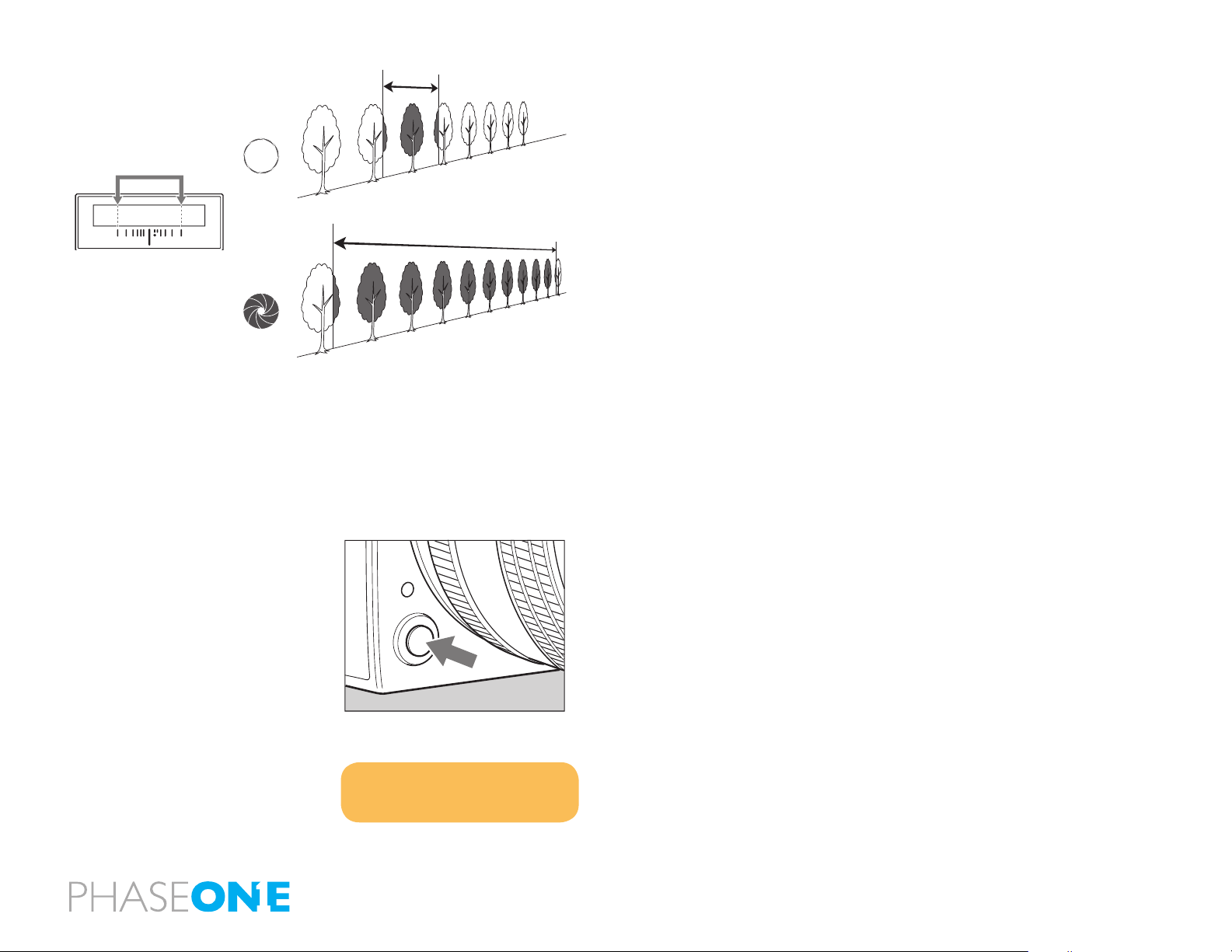
9.12 Depth of Field
Depth of eld (D.O.F.) is dened as the zone of sharpness before and behind
the plane of focus. It depends on distance to subject, focal length of lens,
aperture setting and distance the lens is focused at.
In addition to visual observation via the depth of eld preview button, the
D.O.F. can be determined by using the depth of eld scale on each lens. The f/
stop numbers appear on both the right and left side of the white index mark
in the center of the scale. Simply read the gures which appear above the f/
stop numbers on the distance scale of the lens.
NOTICE:
While operating the preview button, you
cannot release the shutter
Depth of Field Preview Button
When the preview button is pressed in, the depth of eld for the aperture set
on the camera can be checked by looking through the viewnder.
After focusing, press the preview button. The diaphragm will be stopped
down to the set aperture.
Web Resources
http://www.cambridgeincolour.com/tutorials/depth-of-eld.htm
http://en.wikipedia.org/wiki/Depth_of_eld
111
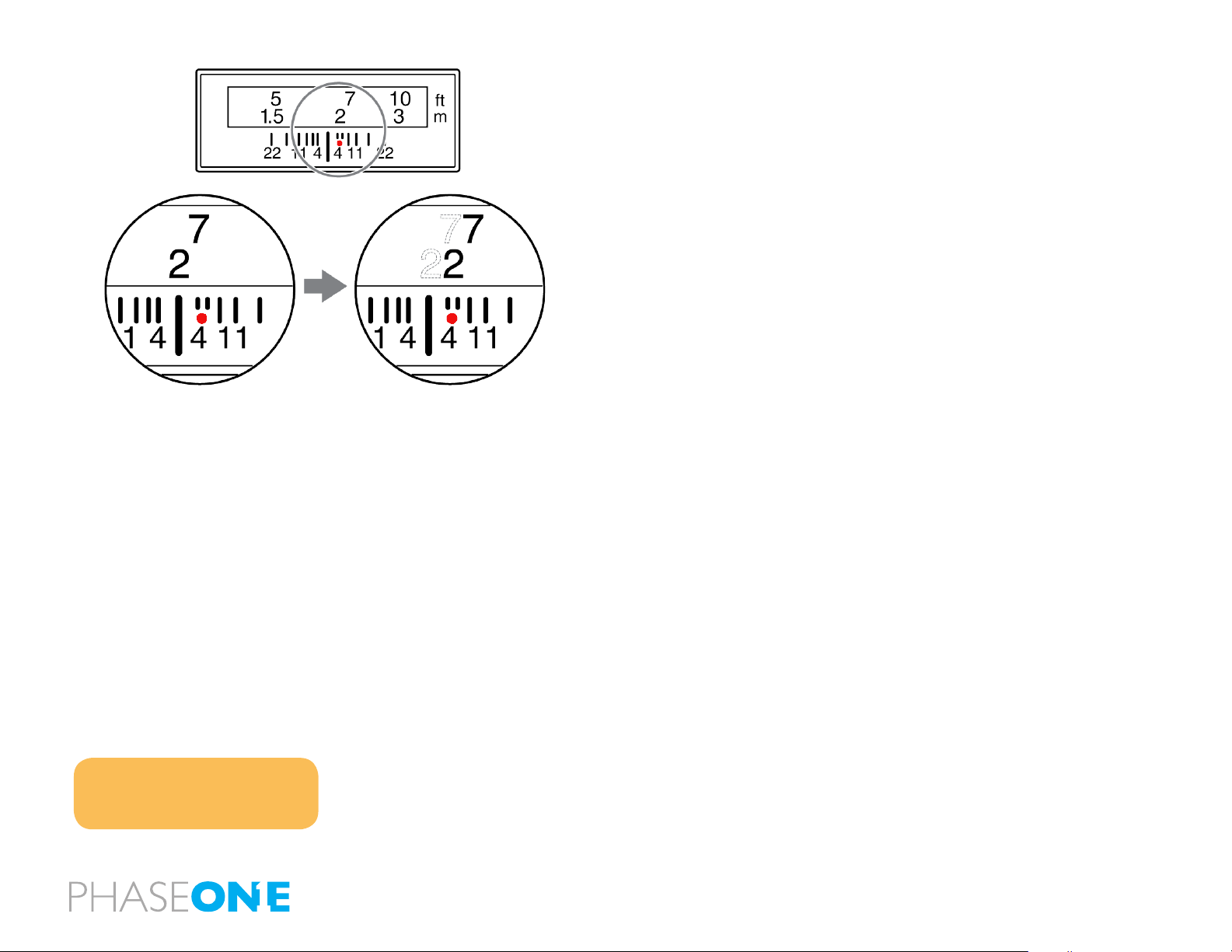
9.13 Infrared Photography
Infrared Photography is complicated when using digital backs, as the digital
back is adjusted to match the viewable light perfectly.
Use a dedicated digital back for infrared photography. The IQ back needs to be
adjusted to work properly for infrared photography. DO NOT TRY THIS AT HOME!
– All corrections in this area must be done by Phase One to ensure precision.
If you remove the protective glass or make other physical adjustments on
the back the warranty will immediately be void.
If you are considering Infrared Photography, please contact your local Phase
One dealer for technical advice and pricing.
Infrared light has a slightly dierent area of sharpness compared to the
viewable light so when the distance is set on the lens, you should always
manually correct sharpness, to be in front of the red dot.
Do not use your camera’s light meter when photographing infrared, as the
light meter is aimed towards reading the visible light.
NOTICE:
You cannot take photos in AE modes when
using an infrared lm as the AE is based on
visible light.
112
9.14 Custom Function
P
C1
Av
C2
Tv
C3
M
CF
X
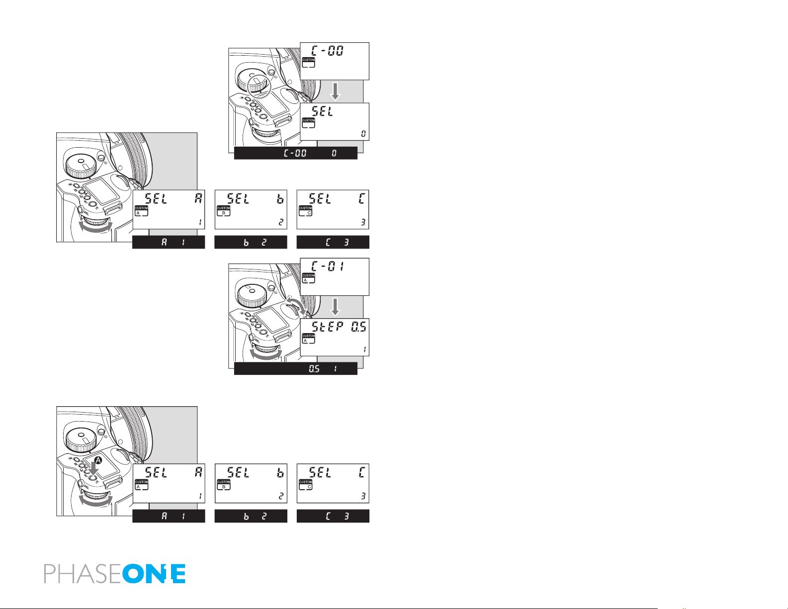
The custom functions can store separate three dierent camera set-ups.
When at C-00, chose 1 (A), 2 (B), or 3 (C) to store a specic set of user function
selections for the group of custom settings from C-01 to C-19.
The C-00 is set to 0 which is the settings used for the default set.
P
C1
Av
C2
Tv
C3
M
CF
X
1. Turn on the power.
Turn the shutter release mode lever to the S or C position.
2. Turn the exposure mode dial to select CF (Custom Function mode).
3. Turn the rear dial to select the settings for user A, B, or C.
4. Turn the front dial to select the item you want to set.
X
CF
M
C3
Tv
C2
Av
C1
P
Clear all Custom Functions
Set mode dial button to CF, then press +/- button for 5 seconds, this will
reset ALL Custom Functions to the factory default.
Setting Custom Functions to Default
1. By turning the exposure mode dial, CF (custom function mode) can be
selected.
2. By turning the rear dial, user A, B or C can be selected.
Setting Custom Functions
P
C1
Av
C2
Tv
C3
M
CF
X
3. Press and hold down set button (for longer than 1 second) and settings
for A,B,C can be initialized, or the settings can be returned to “default”.
113

9.15 Types of Custom Functions
C-00 Custom functions prole [SEL]
0: None (default=0)
1: A
2: B
3: C
When “0” has been selected and set, none of the custom items can be set.
C-01 EV-Steps [StEP]
This function is used to set the size of increments concerning the shutter
speed, f-number and exposure compensation value.
0: 0.3 (1/3EV step: default setting)
1: 0.5 (1/2EV step)
2: 1.0 (1EV step)
0: Alkaline
1: NiCd, NiMH, Li–ion
2: Li-ION (Only for use with Li-Ion battery Kit or Vertical Grip)
C-05 Bracketing [Stno]
Setting bracket’s width for auto bracketing setting
0: 3 Exposures
1: 5 Exposures
2: 7 Exposures
C-06 Front/Rear dial [dF]
This function is used to interchange the functions of the front and rear
dials in the M (manual mode).
0: Front dial: TV, rear dial: Av [OF]
1: Front dial: AV rear dial: Tv [On]
C-02 Lens change [IrIS]
This function is used to set the f-number display method for the previously
used lens when the lenses have been interchanged. The default setting
is “0” in which case the f-number of the lens prior to the changeover is
displayed.
0: Previous f-number
1: Maximum aperture setting
2: Minimum aperture setting
C-03 Sleeptimer [HOLd]
This function is used to set the time for sleep mode to be established after
the camera’s power is turned on. The default setting is 15 seconds.
0: 15 seconds
1: 30 seconds
2: 60 seconds
3: Disabled
The batteries will continuously lose power when “On” (no sleep mode)
has been set.
C-04 Battery Type [batt]
This function is used to set the batteries used in the camera so that the
remaining battery charge will be displayed correctly on the external LCD
panel.
C-07 Rear dial in P mode [d_AC]
Initializing the P mode on the rear dial then changing the function to the
front dial will cancel out P mode function on the rear dial.
0: Enable
1: Disable
C-08 Dial Direction [d_dl]
This function is used to determine the direction in which the electronic dial
is to be rotated to increase and decrease shutter speed, the f-number, and
exposure compensation.
0: CW: Decrease [OF]
1: CW: Increase [On]
C-09 AEL & AFL button [AEFL]
This function is used to set whether to interchange the operations of the
front and rear AEL and AFL buttons.
0: Default setting (front: AFL, rear: AEL) [OF]
1: Switched (front AEL, rear: AFL) [On]
C-10 Release button [HALF]
This function is used to set the AE lock and AF operations when the shutter
release button is half-pressed.
0: AF operation (default setting)
1: AF & AE operation
2: Only shutter release
114

C-11 AEL function lock/unlock mode [AEL]
This function is used to set the method of operating the AEL button to
lock AE. At the default setting, when the AEL button is pressed, AE is
locked; pressing the button again releases the AE lock. At the “1” setting
(released after one shot), after AE lock is set, it is released when the shutter
is triggered. At the “2” setting, AE lock is only kept while the AE lock button
is being pressed.
0: One shot
1: Continuous
2: While pressed
C-12 AFL [AFL]
This function is used to set the AF lock method when the AFL button is
operated. AF >< Lock is activated with one press of the auto-lock button
then deactivated with a second press.
0: While pressed (default setting)
1: AF operation
2: Continuous
C-13 M-mode AEL [OnEP]
When using M (manual mode) one push function, the shutter speed or
aperture value can be set automatically by pressing AEL button.
0: Shutter speed shift [tv]
1: Aperture value shift [Av]
2: No [no]
C-14 AF assist setting [AF_L]
The AF auxiliary light res automatically when the subject is too dark to
perform AF, but this function can be used to prevent the AF auxiliary light
from ring.
0: On [On]
1: O [OF]
C-15 Flash sync. [FLSY]
When shooting moving subjects with ash you can set the synchronization
timing. This allows you to have the ash re at the beginning of the exposure
or at the end of the exposure.
0: First (default setting)
1: Second
C-16 Beep [bu]
When the SET button is pressed a beep sounds
0: ON (AF) (Default setting)
1: ON
2: OFF
C-17 Shutter TV, AV & P [Sh_P]
When using P, Av or Tv mode and the leaf shutter lens is attached but you
prefer to use the focal plane shutter.
0: Mixed. Default (Focal Plane shutter operation at < 1S)
1: Leaf shutter
2: Focal plane shutter
C-18 Shutter in M & X [Sh]
When initializing the setting, use of the lens shutter (and its respective
ranges) or the focal plane shutter can be chosen when the leaf shutter lens
is attached.
0: Mixed. Default (Focal Plane shutter operation at < 1S)
1: Leaf shutter
2: Focal plane shutter
C-19 AF Priority [AF_2]
Accuracy of auto-focusing priority (default setting) or speed priority can be
decided. Use the front dial to scroll to Custom function 19 and the rear dial
to set AF Priority to one of the following:
00: Speed
01: Accuracy
Please note: On IQ, P 65+ or P 40+ digital backs, this CF function can also
be set from within the digital back menu system: Menu > 645DF > Setup
Custom A > AF priority
C-20 AF Fine Tune
Use the front dial to scroll to Custom function 20. Use the rear dial to ne-tune
the focus point on a subject that is closer or further away from the camera.
50: Neutral factory calibration
Minus: Move AF point closer
Plus: Move AF point further away
115
C-97 Support for Mamiya ZD backs
This function should ONLY be activated when shooting on a Mamiya ZD
back.
0: Default setting NO Mamiya ZD back on the camera body
1: Mamiya ZD back on camera body
C-98 Lens rmware version
The current rmware version can be checked.
C-99 Body rmware version
The current rmware version of the body can be checked.
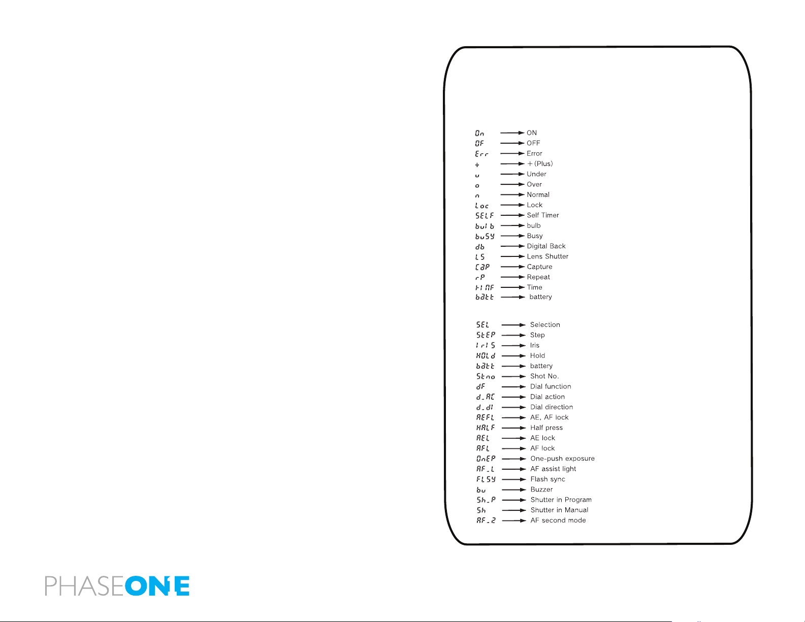
Liquid Crystal Display
Due to the limitations of the space and letters, words and letters on
the LCD are abbreviated.
Display examples of the main LCD
Display examples in the custom function mode
116
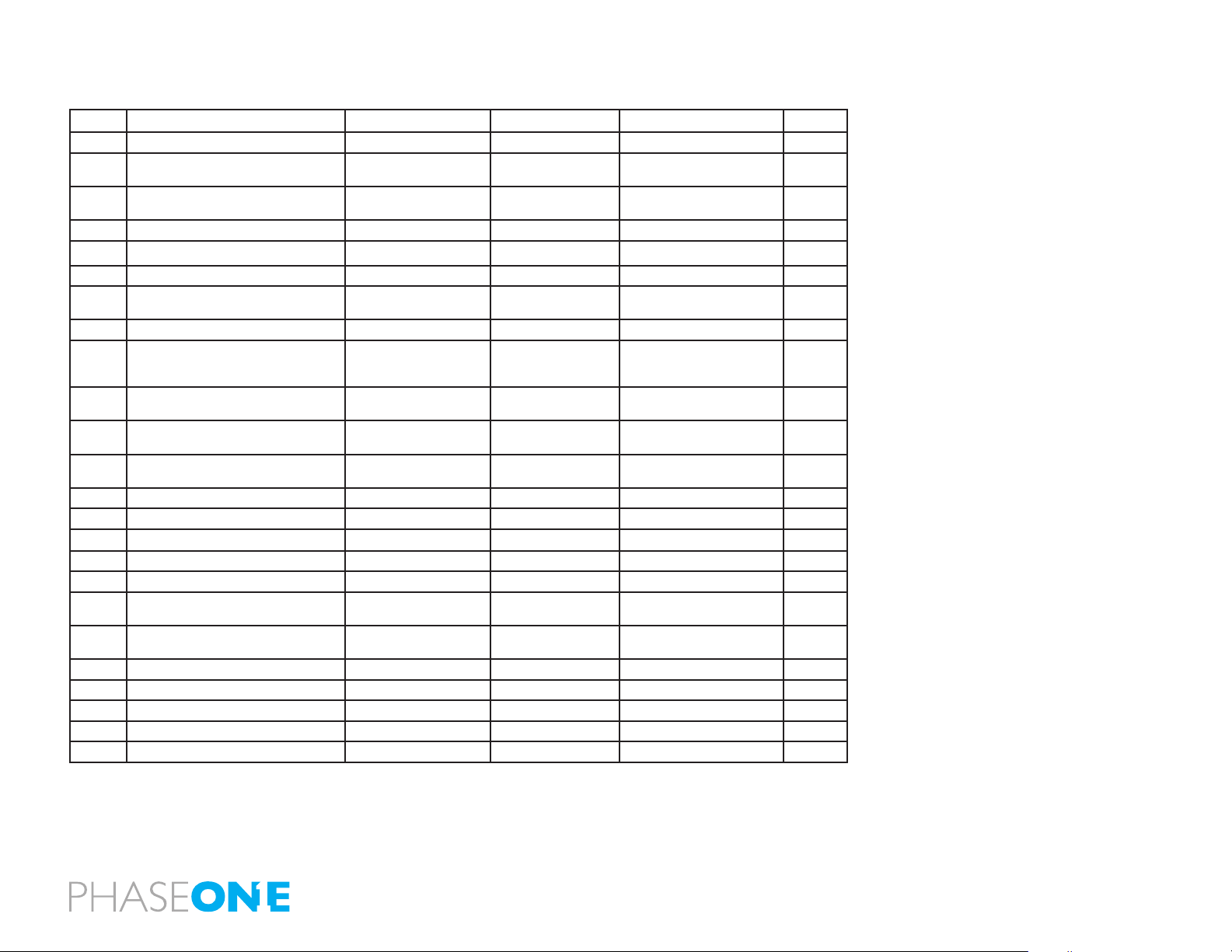
Custom Functions overview
No. Item Initial setting (0) 1 2 3
C-00 Custom Function User Last used User A User B User C
C-01 Steps of aperture, shutter speed,
Exposure compensation
C-02 Aperture setting after lens change Previous aperture value Maximum aperture
C-03 Time to sleep 15 sec 30 sec. 60 sec. ON
C-04 Battery type Alkaline NiMH or NiCD Future feature
C-05 Auto Bracketing steps 3 5 7
C-06 Front/Rear dial function exchange in manual
mode
C-07 Disable Rear dial in P mode Yes No
C-08 Dial Function direction No switching Switched
C-09 AEL & AFL button exchange Front: AFL
C-10 Shutter half-press function AF operation AF operation &
C-11 AEL function lock/unlock mode Continuous One shot While the shutter button is
C-12 AFL lock mode setting Set with AF lock only AF operation Continuous
C-13 One push function M-Mode Shutter speed shift Aperture value shift O
C-14 AF assist beam Fires Does not re
C-15 Flash sync. timing Front Curtain Rear Curtain
C-16 Beep ON (AF) ON OFF
C-17 Choose shutter function (P, Av or Tv mode) Mixed.
C-18 Shutter function in Manual mode Mixed.
C-19 AF Speed High Speed mode High accuracy mode
0.3
1/3 EV step
Front: TV
Rear : AV
Rear : AEL
(When inside the range of the
leaf shutter lens)
(When inside the range of the
leaf shutter lens)
0.5
1/2EV step
Minimum aperture setting
setting
Front:Av
Rear :Tv
CCW : Increase
CW : Decrease
Front: AEL
Rear : AFL
AE Lock
Only Leaf shutter Only Focal plane shutter
Only Leaf shutter Only Focal plane shutter
1.0
1 EV step
OFF
(no function)
pressed
C-97 Mamiya ZD digital back support NO Mamiya ZD back Mamiya ZD back
C-98 Lens Firmware version
C-99 Body Firmware version
117
C2
C1
9.16 Custom Dial Modes C1, C2 or C3
Mode dial options C1, C2 and C3 can be used to store preferred settings.
These settings can be changed instantly to suit the photographer's needs.
Users can change the settings on the camera body or via an IQ back.
Programmable settings are exposure mode, P (program AE), Av (aperture
priority AE), Tv (shutter speed priority AE), X (synchro mode), M (manual
v
v
CF
C3
X
M
Tv
Av
P
T
M
A
X
CF
P
C1
C2
C2
1
mode), focus area and spot metering.
Programming the Custom Dial Modes C1, C2 or C3 via the camera body
1. Go to the setting you wish to assign to C1, C2 or C3.
3
4
2
* The illustration shows the exposure mode Av (aperture priority AE)
being recorded to C2.
NOTICE:
Even when the power is switched o,
the mode recorded will still be saved to
C mode.
2. After arriving at the setting you wish to assign, hold the SET button down
while turning the mode dial to C1, C2 or C3. When you release the SET button,
the chosen setting will be programmed to your selection of C1, C2 or C3.
C1, C2 or C3 modes can be changed while photographing. However after
taking a photo in a mode other than the modes selected in C1, C2 or C3, when
you turn the dial back to a C mode setting the change will not be saved.
118
9.17 Lenses and Multi Mount
When it comes to lenses, Phase One provides the widest range of possibilities
to ensure photographers get the most creative freedom from their Phase
One camera.
This chapter looks at some possible lens systems. However, it is worth noting
that there are even more applicable lenses available than presented in the
upcoming pages. User can nd more information from dedicated Phase One
dealers on items such as mount-adaptors for example the Phase One MultiMount.
N.B. Errors or damage caused by third party products are not covered by the
warranty. Please test new products with caution.
9.18 Functions of the Phase One Lens
The Phase One 80mm f/2.8 is a sharp and well tested digital lens. The lens
is mounted by aligning the white dot on the lens with the white dot on the
camera body. Carefully mount the lens by turning it clockwise, until a click
is heard. If you feel resistance or if you hear a scratching-like sound stop and
retry – NEVER use force when mounting the lens as it should always slide into
place without resistance.
9.19 Function of the Phase One Lens Adaptor
To mount the Phase One Multi-Mount, match the white dot on the camera
up with the white dot on the Multi-Mount and turn slowly clockwise. NEVER
use force to mount the ring. When the Phase One Multi-Mount is mounted
you can t Carl Zeiss/Hasselblad V and Hasselblad 200series lenses on the
camera.
119

9.20 List of Alternative Lenses
Recommended Digital lenses
Producer Specs Limitations Adaptor/Mount notice
Mamiya 28 f.4,5 AFD Mamiya 645AFD Sekor
Mamiya 75-150 f.4,5 Mamiya 645AFD Sekor
Mamiya 35 f.3,5 Mamiya 645AFD
Mamiya 45 f.2,8 Mamiya 645AFD
Mamiya 55 f.2,8 Mamiya 645AFD
Mamiya 150 f.3,5 Mamiya 645AFD
Mamiya 210 f.4,0 Mamiya 645AFD ULD
Mamiya 300 f.4,5 Mamiya 645AFD APO
Mamiya 55-110 f.4,5 Mamiya 645AFD
Mamiya 105-210 f.4,5 Mamiya 645AFD ULD
Schneider Kreutnach 55 f.2,8 Mamiya 645AFD Leafshutter
Schneider Kreutnach 80 f.2,8 Mamiya 645AFD Leafshutter
Schneider Kreutnach 110 f.2,8 Mamiya 645AFD Leafshutter
Producer Specs Limitations Adaptor/Mount Notice
Recommended MF lenses
Mamiya A 500 f.4,5 1+2 Mamiya 645 MF
Mamiya A 300 f.2,8 1+2 Mamiya 645 MF+APO
Mamiya A 200 f.2,8 1+2 Mamiya 645 MF+APO
Mamiya 55 1+2 Mamiya 645 leafshutter
Mamiya 80 f.2,8 N/L 1+2 Mamiya 645 leafshutter
Mamiya 150 f.3,8 N/L 1+2 Mamiya 645 leafshutter
Mamiya 105-210 f.4,5 1+2 Mamiya 645
Mamiya 500 f.5,6 1+2 Mamiya 645
Mamiya 55-110 f.4,5 N 1+2 Mamiya 645
Mamiya 150 f.2,8 1+2 Mamiya 645
Mamiya 300 1+2 Mamiya 645
Mamiya 24 f.4,0 1+2 Mamiya 645
Mamiya 35 1+2 Mamiya 645
Mamiya 150 f.3,5 N 1+2 Mamiya 645
Mamiya 45 1+2 Mamiya 645
Mamiya 210 N 1+2 Mamiya 645
Mamiya 80 f.1,9 1+2 Mamiya 645
Mamiya 55 1+2 Mamiya 645
Mamiya 80 f. 2,8 N 1+2 Mamiya 645
Hartblei MC TS-PC 45 f. 3,5 mamiya/Pentacon six super-rotator tilt/shift
Hartblei MC Hartblei 2x converter pentacon six
Producer Specs Limitations Adaptor/Mount Notice
Arsat MC Arsat 30 f.3,5 sheye Pentacon six
Arsat MC Arsat 45 f.3,5 Wide Angle Pentacon six
Arsat MC PCS Arsat 45 f.3,5 Pentacon six shift
Arsat MC PCS Arsat 55 f.4,5 Pentacon six shift
Arsat MC PCS Arsat 65 f.3,5 Pentacon six shift
Arsat MC Arsat 80 f.2,8 Pentacon six
Arsat MC Arsat 600 f.8,0 Pentacon six Mirror
Lenses usable in combination with Phase One Multi-Mount
Carl Zeiss CFi 30 f.3,5 3 hasselblad V
Carl Zeiss CFE 40 f.4,0 3 hasselblad V
Carl Zeiss CFi 50 f.4,0 3 hasselblad V
Carl Zeiss CFi 60 f.3,5 3 hasselblad V
Carl Zeiss CFE 80 f.2,8 3 hasselblad V
Carl Zeiss CFi 100 f.3,5 3 hasselblad V
Carl Zeiss CFE 120 f. 4,0 3 hasselblad V
Carl Zeiss CFi 150 f.4,0 3 hasselblad V
Carl Zeiss CFE 180 f.4,0 3 hasselblad V
Carl Zeiss CFi 250 f.5,6 3 hasselblad V
Carl Zeiss CFE 350 f.5,6 3 hasselblad V SA
Special purpose lenses
Mamiya 120 f.4,0 MACRO Mamiya 645 MF
Mamiya 50 SHIFT 1 Mamiya 645 MF
Mamiya 645 Auto bellows unit 1 Mamiya 645
Mamiya 80 MACRO 1 Mamiya 645
Other lenses usable in combination with adapter
Hasselblad 30 sheye
Hasselblad 40
Hasselblad 50
Pentacon ektogon 50
Arsat 55mm Shift
Biometar 80mm
Biometer 120mm
Sonnar 180mm
Limitation codes:
1: Stopped down metering not possible
2: Discontinued
3: Leaf shutter disables, only aperture priority
120

NOTICE
Since the Focusing Screen’s surfaces are soft
and easily damaged, handle them carefully.
Never touch the surface with bare ngers.
Should dust settle on it, merely blow away
by using a blower.
10.0 Maintenance
The Phase One 645DF+ generally needs very little maintenance. But this is
A
a professional tool and should be treated with care and caution. Always do
test shots before a photographic session if the camera for any reason has not
been used for a long period of time.
If the Focusing Screen needs cleaning, send
it to the nearest authorized Phase One
service center.
Do not attempt to clean the surface of the
Focusing Screen, as it is very delicate.
Do not touch and damage the mirror in any
way.
A frequently used product should be inspected periodically at the nearest
ocial Phase One repair center. Do NOT try to repair any camera, lens or back
errors or malfunctions – Please consult your local dealer.
10.1 Changing the Focusing Screen
1. Remove the lens.
2. Pull the Focusing Screen Release lever A forward, as illustrated, with
tweezers to ease the Focusing Screen down.
3. Remove the Focusing Screen from the Focusing Screen Frame by grasping
the tab on the edge of the screen with tweezers as illustrated.
4. When installing the screen, pinch the tab of the screen with tweezers, and
place the screen on the screen frame.
5. Push the screen frame up using the tweezers until hearing a clicking sound.
The screen is now properly installed. Never press down on other parts as this
will aect the focus function.
121

Notice:
Make sure to re-install the empty battery
case into the body.
10.2 Battery Socket
Never leave batteries in the socket if the camera or back is not planned to be
used for longer periods.
Keep contacts clean and dry at all times.
The empty battery cassette must be
inserted into the body.
The batteries may generate heat if the
external battery case is connected to the
body while the batteries are loaded on the
body.
M.UP
C
External Battery Socket
Use an external battery case PE401 when using the camera in cold
temperatures where the battery capacity may drop.
1. Turn the shutter release mode selector lever to the L position (power o).
S
L
2. Use a coin or similar object to turn and remove the external battery socket
cap.
3. Remove the battery case from the camera body
4. Connect the external battery case to the body. Connect the plug of the
external battery case in which the batteries are installed, to the external
battery socket.
5. Reinstall the original battery case, from which the batteries were removed,
in the body. Turn the battery case lock to lock it in the body.
A
10.3 Tripod/Electronic Shutter Release Contact
Keep all contacts clean and dry at all time.
B
When using a tripod with 3/8” screw (instead of 1/4” screw) remove the small
screw[A] from the tripod screw hole on the bottom of the body using a plus
screwdriver, then use a coin to remove the tripod screw adapter bushing[B].
You will nd Electronic Shutter Release both on the camera body and on the
back. When used, it is recommended to use the shutter release on the back.
Keep both contacts dry and clean.
122

10.4 Camera Display Error-Notication
When Any of These Displays Appear
When Any of These Displays Appear...
LCD display
The camera caution mark will blink if the camera body detects an abnormality.
Problems
S
Causes and remedies
Remedies
End
123

10.5 Lens Maintenance
Never touch the inner optics of the lens with your ngers. Keep the inner
optics perfectly clean with air, a lens brush or the dry cloth delivered with
the lens.
Do not touch the contacts. Keep the contacts clean with either a dry cloth or
by using a breglass brush. Do not use any other tools on the lens.
The lens is not waterproof. It should be immediately dried with a cloth if
becomes wet. If it is exposed to salt, moisten a cloth, wring it and carefully
clean.
10.6 Back Maintenance
Cleaning the CCD
The Phase One IQ back must have the protection plate tted when it is not
attached to a camera. Dust may accumulate on the IR lter, which will degrade
the image quality if not removed. Please follow the directions included in the
CCD cleaning kit that came with the IQ back.
10.7 IR Filter on the CCD
The IR lter (Infrared reduction lter) is permanently mounted on top of the
CCD. The lter may not be removed for several reasons:
• The focusing of the IQ back camera back will be damaged
• It is only possible to remount the lter without dust getting in between the
lter and the CCD if you have access to special clean room facilities
• The Phase One Product Warranty is terminated
124

10.8 645DF+ Camera Body Specifications
l Open platform for maximum choice and compatibility
l Durable, proven platform for secure operation
l Ergonomic handling and ease of use
l Use Phase One digital lenses, Mamiya AF/AFD lenses or Hasselblad
V lenses
l Exposures from 1/4000s to 60 minutes
l Flash synchronization up to 1/1600 sec.
Shutter speed from 1/4000s to 60 minutes, extremely high flash synchronisation up to 1/1600 second to stop
action with fast shutter speed or flash.
The mirror and viewfinder of the Phase One 645DF+ camera are almost three times larger than those of 35mm
cameras, providing much greater control of focus and composition.
While hosting a complete list of features and custom functions, the Phase One 645DF+ camera is extremely easy
to use. All settings important to the exposure are easily controlled by manual dials and soft buttons.
Camera type Modular 645 AF SLR body
Phase One Digital focal plane lenses,
Lenses
Backs Open platform back mount
Auto focus
Shutter
Flash
Light
Metering
Mirror-Up Electronically-activated by switch on grip
Schneider Kreutznach leaf shutter lenses and
Mamiya 645 AFD lenses
Compatible with Hasselblad V lenses
TTL phase-dierence AF with 3 focus points
Focus conrmation in manual mode
Infrared AF assists for unfailing focus
Auto focus lock for swift AF/ M shift
1/4000s to 60 minutes
Up to 120 frames per minute
Shutter speed bracketing
Focal plane shutter: Up to 1/125s
Leaf shutter lenses: Up to 1/1600s’ 1
curtain ash synchronization
X sync terminal and support for TTL ash
TTL metering (average, spot and auto)
Programmable AEL button
Exposure compensation: +/- 5EV
st
and 2nd
Viewnder
Focusing Screen
Selftimer Self-timer from 2 to 60 sec
Remote
Stop Down
Preview
Tripod Socket 1/4 inch and 3/8 inch included
Power
Requirements
User
conguration
Size W, H, D // 6, 5, 7.2" // 153, 128, 184mm
Weight 35 oz. / 1030g. w/o batteries
Content is subject to change without notice
Fixed prism viewnder
Exchangeable diopter from -5 to +3
LCD panel with full exposure information
Interchangeable focus screens
Laser engraved mask for digital back
Matte, Grid, Checker, Microprism
Screw-in cable release on shutter button
Terminal for electronic triggering devices
Stop down button on front of camera
Rechargeable Li-ion battery or
6 AA batteries (standard or rechargeable)
External battery pack – 6 AA batteries
External AC adapter
3 Custom dial modes for capture settings
36 custom settings
Customizable dials and buttons
125

10.9 Phase One 645DF+ Housing Specication
Camera type : 6x4.5cm format, electronically controlled focal-plane shutter, TTL multiple mode AE, AF single
lens reex
Actual Image size: 56x41.5 mm
Lens mount :
stopped-down exposure metering)
Viewnder : Fixed prism viewnder magnication x0.71; built-in diopter adjustment (-2.5 to +0.5, optional
diopter correction lenses provide adjustment ranges of -5 to -2 diopter and 0 to +3 diopter); built-in eye-piece
shutter
Focusing screen : Interchangeable, Matte (standard), Checker, and Microprism Type C for Non-AF M645 lenses.
Field of view : 94%* of actual image
Viewnder info : Focus mark, defocus mark, warning mark, aperture value, shutter speed, metering mode (A, S,
A/S), exposure compensation value (dierence between set value and metered value) and ash ready/ OK lamp with
TTL Metz connection.
AF method :
to EV18 (ISO 100)
Focus area : Displays the focus area in the viewnder screen
AF assist beam : Activates automatically under low light, low contrast.
Range: 9m (when using AF80mm f/2.8 D lens)
AF lock : By pressing the shutter release button halfway down in the AF-S mode, or by pressing the AFL
button.
Exposure modes : Aperture-priority AE, shutter-priority AE, programmed AE (PH, PL setting possible), and manual
AE meteringmode : TTL metering, center-weighted average (AV), spot (S), and variable ratio (A-S auto)
Increments of shutter : Both the shutter speed and the aperture level can be set to 1/3 or speed and aperture 1/2
using the electronic dial lock function
Metering range : EV 2 to EV 19 (with ISO100 and AF80mm f/2.8 D lens)
Exposure compensation : Expandable to ±5 EV
AE lock : With AEL button; canceled by pressing the button again. When AEL button is pressed, exposure
compensation and metering dierence is displayed in the viewnder. (+-6EV, 1/3 steps in M mode).
Shutter :
Shutter speed : AE 30 to 1/4000 sec. (1/8 step), manual 30 to 1/4000 sec. (1/2 or 1/3 steps), 1 min-60 sec. (1
step), X, bulb (Bulb, electronically controlled), tIME, shutter curtain protection mechanism
Auto bracket shot:Enable with auto bracket button (3 frame shots, 5 frame or 7 frame shot with auto bracketing).
Specify 1/3, 1/2, 2/3 or 1EV steps.
Flash synch : X contact point, 1/125 seconds. Synchro speed can be changed away from terminal.
Mamiya 645 AF Mount, compatible with M645 Mount (manual focus conrmation, focus aid,
TTL phase dierence detection method; sensor: CCD line sensor (I+I type); operating range: EV0
Electronically controlled vertical metal focal-plane shutter. (vertical travel)
Flash control : TTL direct ash control, supports Metz SCA3002 system (SCA3952 Adapter)
Mirror up shot : Select by pressing the mirror up button.
LCD displays : Program AE mode icon, synchro mode icon, shutter speed, aperture, custom function icon, user
function icon, focal plane mode icon, lens shutter mode icon, AE lock icon, auto focus lock icon, mirror up icon, focus
area icon, auto bracketing icon, self timer icon, repeat mode icon, delay mode icon, remaining battery power icon, spot
metering icon, dial lock icon, ash compensation icon, exposure compensation icon, exposure compensation, delay
time.
Sync terminal : X contact (sync speed 1/125 sec.)
Cable release socket : On shutter button
Remote-control terminal : On side of body; electromagnetic cable release RE401 and RS402
Self timer : Self timer intervals can be set from 0.5 to 90 sec.: 0.5-10 sec. by the second, 10 to 90 sec. in 10 sec.
units, 2 to 10 mins by the minute and 10 to 6 mins in units of 10 minutes.
Depth-of-eld conrmation : Preview Button on body
Custom settings : 19 items
Tripod socket : U 1/4 inch and U 3/8 included
Power requirements : Rechargeable Li-ion battery or 6 AA batteries (alkaline or rechargeable)
External power socket : An external battery case can be connected.
Size & weight : 6 ”(W )X5 ”(H)X6 ”(D) / 153(W )X128(H)X152(D)mm
2.3 pounds / 1,030 g (body only)
* This information is based on a linear (horizontal/vertical) measurement.
126

11.0 Software
Capture One Pro is a professional RAW converter and image editing software.
It contains all the essential tools and high-end performance in one package
to enable you to capture, organize, edit, share and print images in a fast,
exible and ecient workow.
Please go to http://help.phaseone.com/en for further information regarding
Capture One. (This online Users Guide can also be found under the Help
menu on Windows and Mac). A PDF of the Capture One User Guide can also
be found on the USB memory stick that came with you IQ back.
11.1 To Import Images...
1. Go to File and select “Import Images…” The dialog box will open to
browse les.
2. Navigate to the applicable folder, card or disk in the Locations tool.
3. Select Capture folder (import location) and type in the job name and
Metadata (copyright, caption) if desired.
4. If you want to select a naming format for the imported les, press “Format” in the Naming tool.
5. You can select all or specic images to import.
6. Press “Import All”. You can continue working while images are imported
in the background.
Inserting a memory card into a card reader will automatically bring up the
Import Images dialog window.
Shooting Tethered
Capture One Pro is also used to shoot tethered from an IQ back. Find out
more on page 53 or for more information please consult the online User
Guide available in the Capture One Help menu or go direct to
http://help.phaseone.com/CO7/Capture/Tethered-Shooting.aspx
127

12.0 End User Support Policy
Phase One guarantee World Class Support and Service with every purchased
product. Please check www.phaseone.com for the latest updated support
policy.
Worldwide Dealer Network
At Phase One we think globally but act locally. Phase One’s products are sold
through a worldwide network of dedicated and competent local partners to
make after-sales support convenient for you.
Phase One’s local partners oer rst line support to their customers. Many
provide additional services such as training, extended warranty agreements,
upgrade programs, and many other services that will add value to your
Phase One investment. Contact your local Phase One partner to discuss your
options. Digital camera back pricing and repairs are also handled locally.
If there is no local partner in your area, then please contact Phase One
directly, and we will assist you directly or through one of our partners.
Find your local Phase One partner or take advantage of Phase One’s wide
range of on-line support tools at http://support.phaseone.com
128

12.1 Web Resources
Phase One oer users a host of online resources including inspire, enthuse
and inform. Find detailed information including User Guides and manuals
about Capture One or our Digital Backs from www.phaseone.com
Knowledge Base
Phase One’s searchable Knowledge Base at http://support.phaseone.com
provides detailed answers to many users questions. This ‘self-service’ site is
free of charge and available to all Phase One owners.
Capture One On-line Support Forums
Go to Phase One’s ocial support forum to share your experiences and
get assistance from other Phase One owners as well as from Phase One’s
Technical Support team at http://support.phaseone.com
Some Phase One partners oer on-line support forums, hosted from their
own web pages. Please note that these forums are governed by separate
rules. Phase One oers no guarantees and assumes no responsibility or
liability with respect to the support provided by our local partners.
Many resources and tutorials are created on voluntary basis, and Phase
One is always interested in seeing your videos, reviews, blogs or websites
concerning Phase One.
PhaseOneDK Ocial YouTube Channel
Check out our Youtube channel that provides access to tutorials, showcases,
technical videos and more at http://www.youtube.com/PhaseOneDK
Twitter, Facebook and Google+
There are plenty of ways to get in touch with Phase One across all the main
social media platforms. Finds us on facebook follows us on Twitter and
connect with us on Google+ for the latest product news, promotions and
much more.
129

130

User Guide: Appendix
13.0 Open Platform – Freedom of Choice
Phase One’s Open Platform policy delivers maximum choice and compatibility
with a wide range of dierent camera platforms.
This section covers the IQ back’s compatibility with the Hasselblad V and
H series, Mamiya RZ67, Phase One 645, Mamiya 645, Contax 645 and View
Camera solutions.
Double Exposure Protection
It is not possible to accidentally double expose an image by capturing one
shot quickly after another when an IQ back is used on cameras such as the
Phase One 645DF+/DF/AF, Mamiya 645DF/AFDIII or Hasselblad 555 ELD
(DIG mode). The electronic communication with the body ensures that the
IQ back is ready before allowing release of the next shot. However, users of
other camera bodies that do not use the electronic interface from the IQ will
have to wait for the ready beep signal before releasing the next shot.
Viewnder Masks
Cameras including the Mamiya RZ67 and Hasselblad V-series need a
viewnder mask as the image area of these models is dierent to the image
sensor size of the three IQ models. Go to page 92 to nd out more about
the IQ sensors and go to page 155 for the full list of focusing Screens and
viewnder masks.
131

13.1 IQ Back and Phase One 645AF/DF/DF+ and Mamiya 645 AFD
The IQ back is fully integrated with the Phase One and Mamiya 645 camera
series and functions as a part of the whole camera system. The IQ back
communicates with the cameras through a fast internal electrical computer
interface.
Find out more about the Phase One DF+ camera and IQ back from page 12.
13.2 Mounting IQ back on the Phase One 645 AF &
Mamiya 645 AFD Series
Ensure that the camera mirror is up and the shutter is open when no digital
back is attached. When attaching the IQ back to the camera body the shutter
will close and the mirror will come down.
1. Place the bottom of the IQ back in the locking mechanism.
2. Press the button (circled above left) with your thumb and lever the back
into place.
3. Release the button to lock into position.
Failure to perform this procedure properly can cause an error with the camera
body where the shutter will continuously open and close. If this occurs, remove
the IQ back and follow steps 1 to 3 again.
132

13.3 More Details: Phase One and Mamiya 645 Series Cameras
Power Management and Shutter Latency
The IQ CCD is put to sleep to reduce power consumption when it is not in
use. The IQ needs to wake up before shooting and the timing of this wake up
signal is referred to as the Latency.
The Phase One and Mamiya 645 camera body response time is independent
of the shutter latency setting so it is therefore recommended to keep the
latency on the Normal (default) setting, as this will ensure a longer battery
life.
Studio Flash Sync on the Camera Body
A ash sync lead should be connected to the camera body when using the
IQ back on Phase One 645AF or 645DF/DF+, Mamiya AFD or AFDII models.
Always use a ash cable and/or equipment that provides grounding for the
ash.
Image Orientation
The CCD in the IQ back is positioned in a landscape orientation. However, the
IQ back has an internal sensor that detects when it has been rotated. Thus,
when the camera is rotated and an image is captured in portrait position
the image will appear correctly oriented on the LCD and in the Capture One
application.
Image (left) features the V-Grip Air. Phase One Part # 71507
133

Exposure Mode Dial
Mirror Up
When using mirror up with the Drive Dial in the M.UP position ensure that
the Exposure Mode Dial and the focus mode are both in Manual mode (M).
It is not possible for the camera to measure light or focus when the mirror is
up. Please consult the Mamiya 645 Instruction manual to learn how to use
Mirror Up.
Shutter Release Button
Drive Dial
*Do not touch the mirror
Mirror*
Viewnder Masking
The image area of the Phase One and Mamiya 645 cameras is approximately
56x42 mm. Viewnder masking is not necessary for IQ280 and IQ260 models
as their light sensitive CCD measures 53.9x40.4 mm.
134

14.0 IQ Back for Mamiya RZ67
The IQ backs are compatible with the Mamiya RZ PRO II and PRO IID with the
use of an adaptor plate.
The 645DF+ version of an IQ back can be used on a Mamiya RZ PRO IID with
a Mamiya RZ PRO IID adaptor plate. (Phase One Part # 70994)
The Hasselblad V version of an IQ back can be used on the older version
Mamiya RZ PRO II with a Mamiya RZ Pro II adaptor. (Phase One Part# 70964)
N.B. It is possible to use a Hasselblad V version of an IQ back on the new
Mamiya RZ67 PRO IID by getting the back mount plate modied with the
following Mamiya service part number: Y22995-RZ.
14.1 Mounting IQ Back on the Mamiya RZ67
1. Place the bottom of the IQ back in the locking mechanism.
2. Press the button at the top of the back with your thumb and lever the back
into place.
3. Release the button to lock into position.
N.B. It is important to ensure that the bottom part of the IQ back is attached
correctly before the upper locking mechanism is pressed together.
Mounting the IQ Back Vertically
The CCD in the IQ back is positioned in a landscape orientation. However, it
is possible to mount the IQ back in an upright orientation to capture images
in a portrait format without having to rotate the camera. The IQ back has an
internal sensor that detects when it has been rotated so images will appear
correctly oriented on the LCD and in the Capture One application.
Mount the IQ back in the portrait position by lining up the adapter mount to the
corresponding indentations on the left side of the back. Press the button (circled
left) and lever the back into place. Release the button to lock into position.
135

14.2 Viewnder Masking
The image area of Mamiya RZ67 at 56x69.5 mm is larger than the size of the
three IQ model’s sensors so it is necessary to insert a viewnder mask.
There are two dierent masks available for the Mamiya RZ67 according to
which IQ is being used. (The size IQ280 and IQ260 models CCD is 53.9x40.4
mm while the IQ140’s CCD measures 43.9x32.9mm). Please check page 155
for the relevant viewnder mask.
1.
3.
2.
4.
Insert a Viewnder Mask
1. Remove the protection tape from the mask.
2. Dismount the prism/waist-level nder and remove the focus screen.
3. Place the viewnder mask in the bracket that holds the focusing screen.
4. Re-mount the viewnder focus screen.
5. Re-attach the prism/waist-level nder.
N.B. Please check the relevant Mamiya RZ67 manual regarding how to
dismount the viewnder and remove the focus screen.
136

14.3 More Details: Mamiya RZ67
Mode Selector
The mode selector on the trigger button should be turned to the white dot
when used with the IQ back. The selector should be set to the orange dot to
avoid draining the small battery when the IQ back is attached to the body
and not in use.
Warning: Even if the IQ back is turned o, the battery will drain slowly if the
orange dot is not selected
Shutter Latency Setting Mamiya RZ PRO II
An IQ back should be set to Normal Latency when it is used with a Mamiya
RZ PRO II.
Shutter Latency Setting Mamiya RZ PRO IID
Select the special Mamiya RZPRO IID camera mode, which available in the
Camera mode menu to ensure that the correct latency setting is used.
Studio Flash Sync on the RZ lens
A ash sync lead should be connected to the port on a lens when an IQ back
is used on a Mamiya RZ67 PRO IID. On the older PRO II, use the ash sync
connector on the Adapter plate. (The ash sync port on the IQ back is for use
with Large format cameras where no digital interface is available).
Mirror Up
Mirror up operation is only recommended if using Mamiya’s own double
cable release.
Double Exposure
Is is only possible to get a double exposure when a Hasselblad V mount
plate is being used. Avoid a double exposure by waiting for a ready-beep
from the IQ back before capturing another image.
137

15.0 IQ Back for Hasselblad V Series
The Phase One IQ back can be mounted on a wide range of Hasselblad
cameras including Hasselblad 555 ELD, 553 ELX, 501 CM and 503 CW.
15.1 Mounting the IQ Back on a Hasselblad V Series Camera
1. Place the bottom of the IQ back in the locking mechanism.
2. Press the button at the top of the back with your thumb and lever the back
into place.
3. Release the button to lock into position.
N.B. It is important to ensure that the bottom part of the IQ back is attached
correctly before the upper locking mechanism is pressed together.
Mounting the IQ Back Vertically
The CCD in the IQ back is positioned in a landscape orientation. However, it
is possible to mount the IQ back in an upright orientation to capture images
in a portrait format without having to rotate the camera. The IQ back has an
internal sensor that detects when it has been rotated so images will appear
correctly oriented on the LCD and in the Capture One application.
Mount the IQ back in the portrait position by lining up the adapter mount
to the corresponding indentations on the left side of the back. Press the lock
button (circled left) and lever the back into place. Release the button to lock
into position.
Warning! DO NOT MOUNT WHILE IN S OR RS MODE
N.B. The Phase One IQ back should not be mounted while the camera is set
to mirror up (S or RS modes). The camera should be set to AS, A or 0 mode.
Also ensure that the lens is not jammed when connecting the ash sync
cable to the Phase One IQ back.
138

15.2 Mounting a Viewnder Mask on a Hasselblad V Series Camera
The image area of a Hasselblad V camera body at approx. 6x6cm is a dierent
size to the three IQ model’s sensors so it is necessary to insert a viewnder
mask.
1.
2.
There are two dierent masks available for
according to which IQ is being used. The size IQ280 and IQ260 models CCD
is 53.9x40.4 mm while the IQ140’s CCD measures 43.9x32.9mm. Please check
page 155 for the relevant viewnder mask.
Hasselblad V series cameras
Insert a Viewnder Mask
1. Remove the protection tape from the mask.
2. Dismount the waist-level nder and remove the focus screen.
3. Place the viewnder mask in the bracket that holds the focusing screen.
4. Re-mount the viewnder focus screen.
5. Slide the waist-level nder back into place.
3.
4.
N.B. Please check the relevant Hasselblad camera manual instructions before
removing the focus screen.
139

15.3 More Details: Hasselblad V Series
Sync Cable
A sync cable is always connected from the lens to the small connector in the
front plate on either the left or right side of the IQ back regardless of which
Hasselblad V type camera used.
Flash Lead Connection
A ash cable is always connected to the F-connector on the IQ back with all
Hasselblad V series cameras.
Mirror Up and Shutter Latency Setting
Set the Latency to Zero when shooting with a Hasselblad V, 903 CW and 905
CW.
Tethered Capture
Plug a FireWire 800 cable into the IQ back for tethered capture to a computer
using Capture One Pro.
140

15.4 Hasselblad 555 ELD
Ensure that the shutter release on the front of the Hasselblad 555 ELD is in
the DIG position when using a Phase One IQ back.
If for any reason you have to use the 555ELD in Film position (E.g. If the DIG
is not working) then set the IQ to Zero Latency.
Shutter Latency Setting
The IQ back can be used with both Normal and Zero latency with the
Hasselblad 555 ELD.
An IQ back has a default Normal latency setting that helps to save battery
life. But users may experience unwanted double exposures when using a
two-shot release cable.
Motor Cable on Hasselblad 555 ELD
A motor cable is not required when using an IQ back on a Hasselblad 555
ELD body.
141

15.5 Hasselblad 553 ELX
When using the IQ back on some Hasselblad motorized bodies (i.e. Hasselblad
ELX or Hasselblad ELM series), a motor cable is supplied to enable users to
re the camera shutter from a computer using the Capture One Pro Capture
button. (See circled button left).
Cable Connections
The cable is connected between the multi-connector on the IQ back and the
DIN connector on the Hasselblad. Ensure that A or AS mode are not used.
WARNING! Please note that the Phase One IQ back should not be mounted
while the camera is set to mirror up (S or RS modes). Make sure that the lens
is not jammed or locked open on the “B” setting when connecting the ash
sync cable to the Phase One IQ back.
Shutter Latency Setting
Set the latency setting to Normal on the IQ back while using a Hasselblad
553 ELX.
142

15.6 Hasselblad 501 CM and 503 CW without Winder
The Phase One IQ back can also be used with mechanical Hasselblad cameras
such as the 501 CM and 503 CW. These cameras are operated in single shot
mode via the shutter release button or a standard cable release.
WARNING! Please note that the Phase One IQ back should not be mounted
while the camera is set to mirror up. Also ensure that the lens is not jammed
or locked open on the “B” setting when connecting the ash sync cable to
the Phase One IQ back.
Shutter Latency Setting
Set the latency setting to Normal on the IQ back while using a mechanical
Hasselblad. Set the latency setting to Zero whilst using the Mirror Up function or if you need to rapidly press the shutter button. Precautions must be
taken not to trigger the shutter too fast when using Normal latency. If any
problems arise, it is recommended that users look at the green LED on the
back while slowly pressing the mechanical trigger on the camera body. Users can safely press the button all the way in the moment the LED ashes.
15.7 Hasselblad 503 CW with Winder CW
WARNING! Please note that the Phase One IQ back should not be mounted
while the camera is set to mirror up. Make sure that the lens is not jammed
or locked open on the “B” setting when connecting the ash sync cable to
the Phase One IQ back.
Set the Shutter Latency to Zero when using a 503 CW winder with an IQ back.
143

15.8 Cables shipped with IQ back for Hasselblad V
Classic and Value Added backs come with all the cables needed for the specic camera platform. A Value Added back also comes with an additional
50300143 cable for use with large format and technical cameras.
Part# 50300145 Motor cable for Hasselblad ELX. (Used for host capture when
the IQ back is used on a Hasselblad ELX body).
Part# 50300148 Sync cable short (For use with all Hasselblad medium format
bodies)
Part# 50300143 Multi connector to Lens sync (for use with Large format - in
two shot mode)
Part# 50300144 This cable is available as a separate purchase only.
From multi connector to mini jack female (for use to adapt older Large format
walk-up cables or older Kapture Group one shot adaptor cables to connect
to the multiport).
144

16.0 IQ Back for Hasselblad H Series
The Phase One IQ (H-mount) digital back is designed specically for
Hasselblad H1 and H2 cameras.
16.1 Mounting the IQ back on the Hasselblad H1/H2
1. Ensure that the mirror is up and the shutter is open. (This is the default
position when no cassette is attached to camera body).
2. Place the bottom of the IQ back in the locking mechanism.
3. Lever the back into place.
4. Do not let go of the back until you hear a clicking noise that signals the
back is locked into position. The mirror will come down and shutter will close
when IQ back is attached to the camera.
N.B. It is important to ensure that the bottom part of the IQ back is attached
correctly before the upper locking mechanism is pressed together.
Removing the IQ back from the Hasselblad H1/H2
1. Rotate and press the silver button (illustrated left) to unlock the back.
(Ensure that the back is supported in your hand before pressing this button).
2. Gently lever away the top of the back rst. Be careful with the contacts
and protective glass on the back.
N.B. Your IQ back should always be protected by its plate when it is not
attached to the camera.
145

16.2 Viewnder Masking
The image area of the Hasselblad H1/H2 cameras is 56x41.5 mm. A viewnder
mask is only needed for the smaller size of the IQ140 CCD that measures
44x33mm. Viewnder masking is not necessary for IQ280 and IQ260 models
as their light sensitive CCD measures 53.9x40.4 mm.
Please check page 155 for the relevant viewnder mask.
1.
3. 4.
2.
Insert a Viewnder Mask
1. Remove the protection tape from the mask.
2. Dismount the prism/waist-level nder and remove the focus screen.
3. Place the viewnder mask in the bracket that holds the focusing screen.
4. Re-mount the viewnder focus screen.
5. Re-attach the prism/waist-level nder.
N.B. Please check the relevant Hasselblad H-series manual regarding how to
dismount the viewnder and remove the focus screen.
146

16.3 More Details: Hasselblad H Series
Camera Display
The Hasselblad H1/H2 incorporates a screen that displays information about
the camera set-up. It shows the aperture value, AF mode, shutter speed etc.
The Hasselblad H1/H2 will also display some IQ back information on this
screen. For example, error messages including ”Digital back storage media
is full” will be displayed on the screen if the CompactFlash in the IQ back is
full to capacity.
ISO Settings
The ISO value is also displayed on the H1/H2 camera screen. The ISO setting
can be adjusted from the camera back or in Capture One software when
shooting tethered.
Please consult page 61 of this manual for details on setting the ISO. Go to
page 53 for more information about tethered shooting.
Auto Exposure
All the Hasselblad H1/H2 auto exposure modes are fully supported by the
IQ back.
Please check the relevant Hasselblad H-series manual for more information
on exposure modes.
147

Viewnder Information
The viewnder information bar is located below the image area within
the viewnder display. It displays the camera’s exposure mode and values
etc. It also includes a counter with the number of captures remaining on
the storage media. (See top bar circled left). ‘99’ is the maximum number
displayed. ‘99’ will continue to be displayed if there are more than that
remaining on a CompactFlash card. An ‘E’ indicates that the storage media
is full. Users will have to delete some captures or replace the CompactFlash
card before continuing. (See bottom bar circled left).
Double Exposure Protection
It is not possible to accidently double expose an image by capturing one
image quickly after another when an IQ back is used on a Hasselblad H1/H2.
N.B. At the end of an exposure, image information has to be moved from the
CCD to the processing system. During this short period of time the CCD must
be protected from light exposure. The IQ back ensures that the CCD is safely
cleared of information by disabling the Hasselblad camera’s shutter release
during this procedure.
Image Orientation
The CCD in the IQ back is positioned in a landscape orientation. However, the
IQ back has an internal sensor that detects when it has been rotated. Thus,
when the camera is rotated and an image is captured in portrait position
the image will appear correctly oriented on the LCD and in the Capture One
application.
148

Flash Lead Connection
A ash cable is always connected to the Hasselblad H1/H2 camera body.
The ash sync cable must not be connected to the camera back when used on
a Hasselblad H1/H2. The ash sync connector on the IQ back is only intended
for use with a Phase One FlexAdaptor or other large format adaptors.
16.4 Cables Shipped with IQ back for Hasselblad H
No cables are required to use the IQ back with a Hasselblad H1/H2.
A Value Added IQ back comes with an additional multi-connector to Lens
sync cable (part# 50300143) for use with large format cameras in two shot
mode.
Part# 50300144 This cable is available as a separate purchase only.
From multi-connector to mini jack female (for use to adapt older Large
format wake-up cables or older Kapture Group one shot adaptor cables to
connect to the multiport).
149

17.0 IQ Back for Contax 645
The Phase One IQ (Contax mount) digital back is designed specically for the
Contax 645 camera. The IQ back communicates with the Contax 645 through
a fast internal electrical computer interface and utilizes TTL phase dierence
detection type auto focus system.
17.1 Mounting IQ Back on a Contax 645
1. Place the bottom of the IQ back in the locking mechanism.
2. Press the button at the top of the back with your thumb and lever the back
into place.
3. Release the button to secure it into position.
4. Lock the IQ back into place by sliding the switch left towards the release
button. (See switch circled below left).
N.B. It is important to ensure that the bottom part of the IQ back is attached
correctly before the upper locking mechanism is pressed together.
Removing the IQ back from the Contax 645
1. Slide the locking switch to the right position.
2. Press the button (circled left) to unlock the back. (Ensure that the back is
supported in your hand before pressing this button).
3. Gently lever away the top of the back rst. Be careful with the contacts
and protective glass on the back.
N.B. Your IQ back should always be protected by its plate when it is not
attached to the camera.
150

17.2 Viewnder Masking
The image area of the Contax 645 camera is 56x41.5 mm. A viewnder mask
is only needed for the smaller size of the IQ140 CCD that measures 44x33mm.
Viewnder masking is not necessary for IQ280 and IQ260 models as their
light sensitive CCD measures 53.9x40.4 mm.
Please check page 155 for the relevant viewnder mask.
1.
3.
2.
4.
Insert a Viewnder Mask
1. Remove the protection tape from the mask.
2. Dismount the prism/waist-level nder and remove the focus screen.
3. Place the viewnder mask in the bracket that holds the focusing screen.
4. Re-mount the viewnder focus screen.
5. Re-attach the prism/waist-level nder.
N.B. Please check the relevant Contax 645 manual regarding how to dismount
the viewnder and remove the focus screen.
151

17.3 More Details: Contax 645
Exposure Modes
The Contax 645 manual (M) and semi-auto exposure modes (Av, Tv) are fully
supported by the IQ back. Please note that Bulb is only supported on Contax/
IQ back when used in conjunction with the Live View function. Go to Chapter
20 (from page 156) for more information about Live View.
Please check the relevant Contax 645 manual for more information on
exposure modes.
Ensure that exposure times are limited between 1/4000 second and approx.
1 second to obtain the highest possible quality with an IQ back and Contax
645. Please note that it is not possible to expose images longer than 60
seconds with an IQ back.
ISO Settings
The Contax 645 exposure modes use the ISO value set in the IQ back. The ISO
setting can be adjusted from the camera back or in Capture One software
when shooting tethered.
Please consult page 61 of this manual for details on setting the ISO. Go to
page 53 for more information about tethered shooting.
Double Exposure Protection
It is not possible to accidently double expose an image by capturing one
image quickly after another when an IQ back is used on a Contax 645 e.g.
when using the continuous drive mode.
152

TTL ash
Using TTL ash with the Contax 645 camera and IQ back will result in a 2
f-stop overexposure. When using TTL ash, the exposure compensation on
the ash unit must therefore be set to –2 f-stops.
This overexposure happens because the CCD element reects light dierently
than lm and this cannot be communicated to the Contax.
Image Orientation
The CCD in the IQ back is positioned in a landscape orientation. However, the
IQ back has an internal sensor that detects when it has been rotated. Thus,
when the camera is rotated and an image is captured in portrait position
the image will appear correctly oriented on the LCD and in the Capture One
application.
17.4 Flash Lead Connection
A ash cable is always connected to the Contax 645 camera body.
The ash sync cable must not be connected to the camera back when used
on a Contax 645. The ash sync connector on the IQ back is only intended for
use with a Phase One FlexAdaptor or other large format adaptors.
153

17.5 Cables Shipped with IQ back for the Contax 645
(Value added only)
Part# 50300143 Multi-connector to Lens sync (for use with Large format - in
two shot mode)
Part# 50300144 This cable is available as a separate purchase only.
From multi-connector to mini jack female (for use to adapt older Large
format wake-up cables or older Kapture Group one shot adaptor cables to
connect to the multiport).
Part# 50300154 From multi-connector to mini jack on the Contax handgrip
(used to enable Host Capture from Computer)
N.B. Operating the camera from the host computer
The supplied release cable must be connected between the multiple-pin
connector on the IQ back and the mini-jack connector placed at the bottom
of the handgrip on the Contax camera house.
154

18.0 IQ Back for View Cameras
The Phase One IQ back is compatible with most technical view cameras and
large format cameras via camera interface adaptors. The IQ back supports
most mechanical shutters and some electronic shutters from Horseman,
Schneider and other manufacturers.
Phase One Sleeping Architecture
The Phase One Sleeping Architecture has been developed to help produce
noise free exposures without the use of active cooling of the CCD. The
sleeping architecture ensures minimum heat build up inside the back by
putting all the unused circuits to sleep, and only powering the circuits that
are actually needed at any given time.
155

18.1 Using the 2-shot Release
The IQ back can be used with mechanical shutters that can be red twice
within four seconds. The rst release of the shutter activates the digital
back; the second release is for the exposure. If the time limit of four seconds
is exceeded, the camera gives a warning ‘beep’ followed by a ‘two shoot
error’ warning that will be displayed on the LCD screen.
There are several automatic or semi-automatic two shoot solutions available
from third parties manufacturers to use with a mechanical shutter. Please ask
your dealer for more information.
18.2 Using the 1-shot Release
The 1-shot release cable is created to simplify your studio workow.
1. Connect the ash exit (circled left) on the shutter and plug the opposite
end to the multi-pin port on the IQ back. (Via Part# 50300144 From multiconnector to mini jack female)
2. Connect a ash sync lead to the port on the IQ back.
3. Close the shutter if necessary.
4. Push the button on the 1-shot release lead to ‘wake up’ the camera back .
(circled left) and take the shot within a few seconds.
N.B. It is not possible to control the exposure or trigger the shutter from
Capture One when using a fully manual camera. Only limited EXIF data
is recorded when shooting with manual cameras. The IQ back will add a
calculated approximate shutter speed but the aperture value will not be
recorded.
156

18.3 Phase One FlexAdaptor
The Phase One FlexAdaptor is available for use with most large format
cameras.
The Phase One FlexAdaptor can automatically stitch two or three images
together using the Stitch function in Photoshop.
Please see the reference manual that comes with the FlexAdaptor for more
details.
18.4 Shutter Latency Settings for the FlexAdaptor and Other
Technical Camera Adaptors
The Phase One FlexAdaptor and other technical camera adaptors for the IQ
back can be used with both normal and zero shutter latency.
Select the Normal latency setting if the IQ back is used on a camera with a
2-shot release. (See 18.1)
Please note: The Zero shutter latency setting will increase the power
consumption of the IQ back, as it will be constantly prepared for exposure.
157

19.0 List of Focusing Screens and Viewnder Masks
19.1 Full Frame Focusing Screens or with Engraved Masking
Part #
70756 Focusing Screen for Phase One 645 Camera
(Standard Full Frame IQ280/IQ260)
70754 Focusing Screen IQ140 for Phase One 645 Camera
70757 Focusing Screen for Phase One 645 Camera SD402
(Checker Grid)
70758 Focusing Screen for Phase One 645 Camera SA402
(Microprism for non AF lenses)
19.2 Viewnder Masks
Part #
40101906 Viewnder Mask for Phase One IQ140 for Hasselblad H1/H2
40101903 Viewnder Mask for Phase One IQ140 for Phase One/
Mamiya 645 AFD
40101905 Viewnder Mask for Phase One IQ140 for Contax 645
40101901 Viewnder Mask for Phase One IQ140 for Hasselblad V
40101929 Viewnder Mask for Phase One IQ140 for Mamiya RZ
40102056 Viewnder Mask for Phase One IQ260/IQ280 for Mamiya RZ
0102044 Viewnder Mask for Phase One IQ260/IQ280 for Hasselblad V
158

20.0 Live View
The Live View function is intended for use when a camera is mounted on a
tripod and the subject is stationary.
Live View is ideal for use with technical view cameras in a studio environment or for architectural photography, where photographers would ordinarily have to rely on an external viewnder or a separate focusing glass /
sliding adaptor.
The Live View function enables photographers to compose an image
directly on the high resolution display of the IQ digital back. Focus can be
checked by zooming into a subject on the screen by up to 400%.
159

20.1 Starting Live View
1. Live View is accessed from the Context Menu (circled left) in the lower
right corner.
The Context menu is always visible on the Home screen. Tap the lower right
corner of the screen to reveal the icon if it is hidden in some of the Play
mode displays.
2. Select the Live View (movie camera) icon from the context menu. (Circled
left).
3. When Live View is activated ensure that a Live View white balance is
applied. Tap the lower right corner of the screen to bring up the context
menu and select the White Balance Picker (Circled left).
Go to page 158 for more information about Live View white balance.
160

20.2 White Balance
1. After selecting the White Balance Picker, tap the screen to select a neutral
area to calibrate the Live View.
2. If a precise white point is dicult to achieve in full screen view, slide a
nger on the left side of the screen to zoom into to a part of the image that
you want to use as white reference.
Exit the White Balance mode by deselecting the picker in the context menu.
Alternatively, press and hold the upper left physical button on the IQ back
to return to the Home screen.
Go to page 159 to nd out more about the zoom function.
20.3 Quality and Brightness
1. Go to the context menu and select the Live View exposure controls icon
(circled left).
2. Two sliders will appear at the bottom of the screen to help users adjust
the live view to suit the ambient lighting conditions being used. The top
slider is a speed vs. quality slider. Increase the quality by moving slide to the
right or achieve a faster frame rate on the left. The lower slider controls the
brightness of the Live View.
161

20.4 Zoom
Zoom into the live view by sliding a nger up in the left side of the screen.
Double tap on the image to bring up a 100% view. If a zoom is already applied, double tap the screen to return to a full image view.
20.5 Grid
1. Go to the context menu and select the Grid icon (circled left) to apply
a default grid. Press and hold the Grid icon to select one of a selection of
other grid options to apply to the live view.
20.6 Auto Stop and Start
Live View will be paused if the screen is not touched for one minute.
Touch the screen again to restart Live View.
162

20.7 Accessories
Live View is easily overexposed in due to the high sensitivity of the IQ CCD
sensor and its large size. It is sometimes necessary to take steps to prevent
overexposure by either stopping down the aperture or by using a Neutral
Density lters (ND lters ). ND lters are widely available, and it is even possible to get variable ND lters, that can prove invaluable when working in
changeable outdoor ambient light.
Recommended Suppliers
Schneider Optics:
http://www.schneideroptics.com/lters/index.htm
Lee Filters:
http://www.leelters.com/camera/products/nder/ref:C475674681BB1B/
Sing Ray Vari ND:
http://www.singh-ray.com/varind.html
163

20.8 Live View Camera Support
The Phase One IQ back Live View function is supported on both medium
and large format view cameras. Find out how to operate Live View from the
following list of cameras:
View Cameras
1. Open the lens and select the desired aperture value.
2. Activate Live View on the IQ back.
Phase One 645AF/645DF/645DF+
1. Activate Live View on the IQ back.
2. Adjust the exposure time dial until the camera display states ‘time’.
3. Press the camera shutter button.
Hasselblad H1/ H2
1. Activate Live View on the IQ back.
2. Select the M (Manual) mode.
3. Select the desired aperture value.
4. Set the shutter to ‘T mode’ .
N.B. It is only possible to change the aperture when the camera body is
idle/not exposing. Please exit the T-mode to change aperture.
164

Hasselblad V
1. Activate Live View on the IQ back.
2. Select B (Bulb) mode.
Mamiya RZ67 Pro II/Pro IID
1. Activate Live View on the IQ back.
2. Select B (Bulb) mode.
N.B. It is only possible to change the aperture when the camera body is
idle/not exposing. Please exit the Bulb mode to change aperture.
Contax 645
1. Activate Live View on the IQ back.
2. Select B (Bulb) mode.
3. Select the desired aperture value.
N.B. It is only possible to change the aperture when the camera body is
idle/not exposing. Please exit the Bulb mode to change aperture.
165
 Loading...