

Page 1

Wireless Module
All Rights Reserved. SparkLAN may make changes to specification and descriptions at any time without prior notice.
www.sparklan.com / sales@sparklan.com / +886 2 2659-1880
WPEQ-261ACNI(BT)
ver.1.0
Embedded Application
Applications include medical devices,
security systems, industrial PC, Point of Sale,
digital signs, set-top/net-top box, embedded
/ tablet PC’s, Vehicle mounted front, Robot/
Intelligent Gateway, Gaming machine, etc.
Key Feature
● Supports low power PCIe (w/L1 substate) interfaces
for WLAN and USB1.1 interface for Bluetooth.
● Support Bluetooth 4.2 + HS, BLE, ANT+ and be backwards
compatible with Bluetooth 1.2, 2.X + enhanced data rate.
● Supports 20/40 MHz at 2.4 GHz and supports 20/40/80 MHz
at 5 GHz (SW PL determines 2.4 GHz HT40/VHT40 support)
● Compatible for 5 GHz 802.11ac, or 2.4/5 GHz 802.11n WLAN
applications.
WPEQ-261ACNI(BT)
WPEQ-261ACNI(BT) is high performance 802.11ac/a/b/g/n dual band 2T2R Industrial-Grade (-40°C ~+85°C)
Wi-Fi / Bluetooth 4.2 combo mini PCIe module, multiple output (MU-MIMO) with two spatial streams
IEEE802.11 ac/a/b/g/n WLAN standards and Bluetooth 4.2+HS, designed to deliver superior integration of
WLAN / Bluetooth and low energy technology.
It supports Windows and Linux Drivers solution. WPEQ-261ACNI(BT) is using a QCA6174A along with
Windows and Linux driver which provide excellent solution for Automation / Robotic various applications.
Adopting the latest 802.11ac solution. WPEQ-261ACNI(BT) is dual band AC on 2.4GHz+5GHz and
incorporates the latest Bluetooth 4.2. The download speed are 300Mbps on N networks and 867Mbps on
AC network. WPEQ-261ACNI (BT) is integrates the Bluetooth transmission technology for voice and data
transfers between devices in a short distance.
Certification
Dipole Ant.
■ FCC ■ CE (RED EN 300 328 V2.1.1 / EN 301 893 V2.1.1)
■ IC ■ MIC
□ NCC □ ASNZS
Page 2

Wireless Module
All Rights Reserved. SparkLAN may make changes to specification and descriptions at any time without prior notice.
www.sparklan.com / sales@sparklan.com / +886 2 2659-1880
WPEQ-261ACNI(BT)
ver.1.0
Standards
IEEE 802.11ac/a/b/g/n (2T2R)
Bluetooth V4.2, V4.0 LE, V3.0+HS, V2.1+EDR
Chipset
Qualcomm QCA6174A
Data Rate
802.11b: 11Mbps / 802.11a/g: 54Mbps / 802.11n: MCS0~15/ 802.11ac: MCS0~9
Bluetooth: 1 Mbps, 2Mbps and Up to 3Mbps
Operating Frequency
IEEE 802.11 ac/a/b/g/n ISM Band, 2.400GHz~2.497GHz, 4.900GHz~5.845GHz
*Subject to local regulations
Interface
PCIe: WLAN / USB: Bluetooth
Form Factor
Half Mini PCIe
Antenna
2xIPEX connectors (ANT1 for WIFI+BT, ANT2 for WIFI)
Modulation
802.11b: DSSS (DBPSK, DQPSK, CCK)
802.11a/g: OFDM (BPSK, QPSK, 16-QAM, 64-QAM)
802.11n: OFDM (BPSK, QPSK, 16-QAM, 64-QAM)
802.11ac: OFDM (BPSK, QPSK, 16-QAM, 64-QAM, 256-QAM)
Power Consumption
TX: 610mA / RX: 285mA
Operating Voltage
DC 3.3V
Operating Temperature Range
-40°C~+85°C
Storage Temperature Range
-40°C~+85°C
Humidity
(Non-Condensing)
5%~90% (Operating)
5%~90% (Storing)
Dimension (in mm)
29.85mm (±0.15mm) x 26.65mm (±0.15mm) x 2.65mm (±0.2mm)
Weight (g)
≦ 6g
Driver Support
Windows 7/8.1/10
Linux (Open Source), Recommend Kernel v4.0+
Security
64/128-bits WEP, WPA, WPA2, 802.1x
Specification
Page 3
Wireless Module
All Rights Reserved. SparkLAN may make changes to specification and descriptions at any time without prior notice.
www.sparklan.com / sales@sparklan.com / +886 2 2659-1880
WPEQ-261ACNI(BT)
ver.1.0
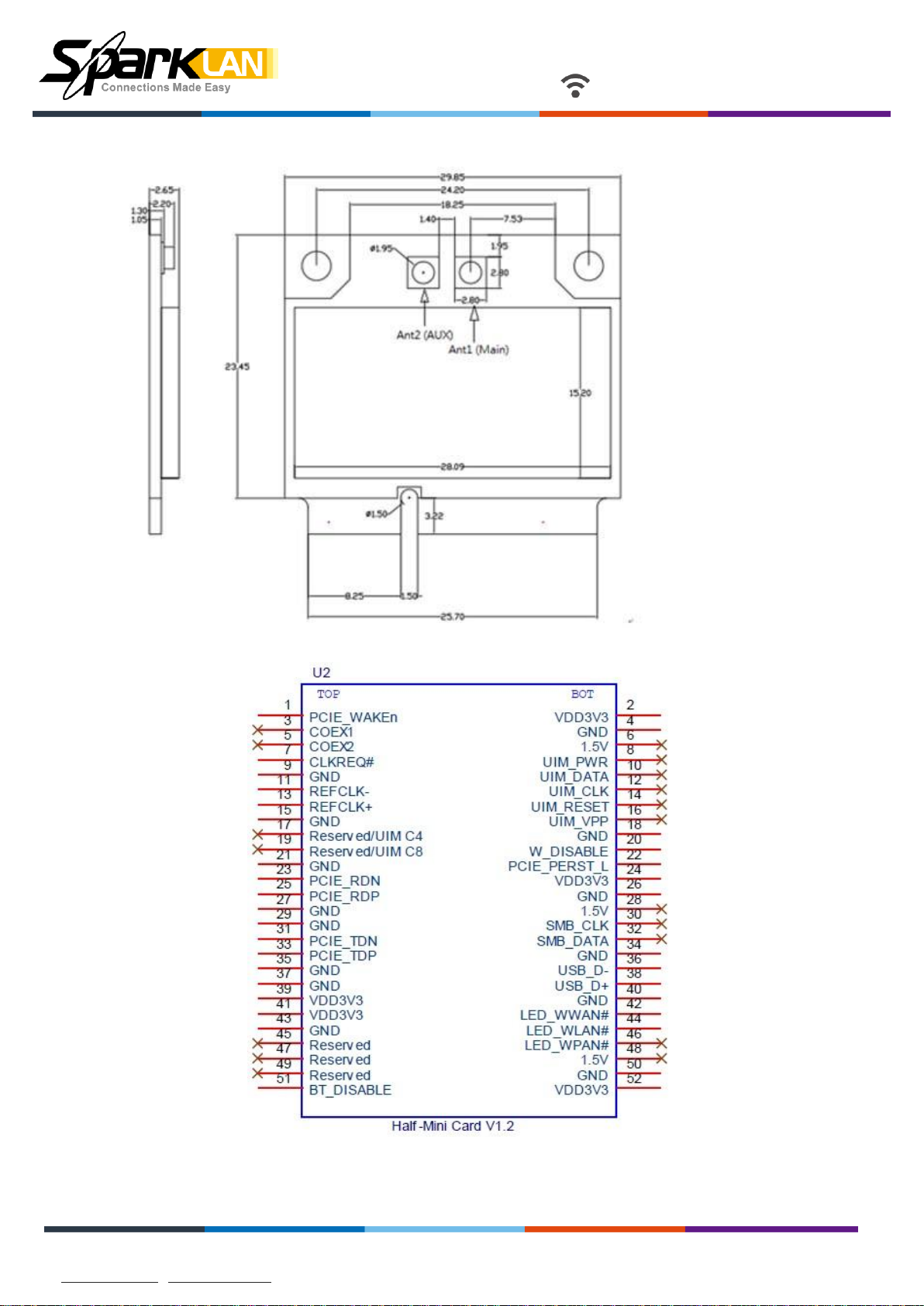
Mechanical Dimension (mm)
Pin Assignment
Page 4

Wireless Module
All Rights Reserved. SparkLAN may make changes to specification and descriptions at any time without prior notice.
www.sparklan.com / sales@sparklan.com / +886 2 2659-1880
WPEQ-261ACNI(BT)
ver.1.0
TOP
Pin#
Pin Name
Type
Description
1
PCIE_WAKE_L
O
PCIe wake signal
3
NC - No connect
5
NC - No connect
7
PCIE_CLKREQ_L
I/O
PCIe clock request
9
GND
-
Ground connections
11
PCIE_RCLK_P
I
PCI Express differential clock input- Positive
13
PCIE_RCLK_N
I
PCI Express differential clock input- Negative
15
GND
-
Ground connections
17
NC - No connect
19
NC - No connect
21
GND
-
Ground connections
23
PCIE_TX_P
O
PCI Express transmit data- Positive
25
PCIE_TX_N
O
PCI Express transmit data- Negative
27
GND
-
Ground connections
29
GND
-
Ground connections
31
PCIE_RX_N
I
PCI Express receive data-Negative
33
PCIE_RX_P
I
PCI Express receive data-Positive
35
GND
-
Ground connections
Pin Assignment
Page 5

Wireless Module
All Rights Reserved. SparkLAN may make changes to specification and descriptions at any time without prior notice.
www.sparklan.com / sales@sparklan.com / +886 2 2659-1880
WPEQ-261ACNI(BT)
ver.1.0
37
GND
-
Ground connections
39
VDD_3V3
I
VDD system power supply input
41
VDD_3V3
I
VDD system power supply input
43
GND
-
Ground connections
45
NC - No connect
47
NC - No connect
49
NC - No connect
51
BT_RF_KILL_L
-
Turn off BT RF analog and front-end. Active low
BOTTOM
Pin#
Pin Name
Type
Description
2
VDD_3V3
I
VDD system power supply input
4
GND
-
Ground connections
6
NC - No connect
8
NC
-
No connect
10
NC
-
No connect
12
NC
-
No connect
14
NC
-
No connect
16
NC
-
No connect
18
GND
-
Ground connections
20
WLAN_RF_KILL_L
I
Turn off WLAN RF analog and front-end. Active low.
22
PCIE_PERST_L
I
PCIe host indication to reset the device Active low.
24
VDD_3V3
I
VDD system power supply input
Page 6
Wireless Module
All Rights Reserved. SparkLAN may make changes to specification and descriptions at any time without prior notice.
www.sparklan.com / sales@sparklan.com / +886 2 2659-1880
WPEQ-261ACNI(BT)
ver.1.0
26
GND
-
Ground connections
28
NC
-
No connect
30
NC
-
No connect
32
NC
-
No connect
34
GND
-
Ground connections
36
USB_D-
I/O
USB serial differential data Negative
38
USB_D+
I/O
USB serial differential data Positive
40
GND
-
Ground connections
42
WLAN_LED
OD
WLAN LED
44
BT_LED
OD
Bluetooth LED
46
NC
-
No connect
48
NC
-
No connect
50
GND
-
Ground connections
52
VDD_3V3
I
VDD system power supply input
Hardware Setup:
Insert WPEQ-261ACNI(BT) into the mini pcie slot of end product.
Connects two external antenna at I-PEX connectors on the board.
Note to the voltage level should be 3.3V.
Software setup:
Page 7

Introduction
The Atheros 802.11n + Bluetooth Adapter supports 802.11n and Bluetooth EDR2.0
operation. The card uses the Atheros Client Utility (ACU) which is a user-mode utility
designed to edit and add profiles for selected Atheros network interface adapters.
System Requirements
Laptop/ PC containing:
32-bit PCI Express Bus
32 MB memory or greater
300 MHz processor or higher
Microsoft Windows 2000, Windows Millennium Edition, Windows 98 Second
Edition, Windows XP, or Windows NT 4.0 (with Service Pack 6)
Profile Management
Configure the wireless network adapter (wireless card) from the Profile Management tab
of the Atheros Client Utility.
Add a profile
Edit a profile
Import a Profile
Export a Profile
The wireless network adapter works in either infrastructure mode (which uses an access
point) or ad hoc mode (a group of stations participating in the wireless LAN).
Order profiles
Switch to a different profile
Remove a profile
Connect to a Different
Network
Create or Modify a Configuration Profile
To add a new configuration profile, click New on the Profile Management tab. To modify
a configuration profile, select the configuration from the Profile list and click the Modify
button.
The Profile Management dialog box displays the General tab. In profile management:
Edit the General tab.
Edit the Security tab.
Edit the Advanced tab.
To configure a profile for ad hoc or access point (infrastructure) mode, edit the Network
Type field on the Advanced tab.
Note that the ACU only allows the creation of 16 configuration profiles. After the
creation of 16 profiles, clicking the New button displays an error message. Remove an
old profile or modify an existing profile for a new use.
Page 8

Remove a Configuration Profile
1. Go to the Profile Management tab.
2.
Select the profile to remove from the list of configuration profiles.
3.
Click the Remove button.
Auto Profile Selection Management
Including a profile in the auto selection feature allows the wireless adapter to
automatically select that profile from the list of profiles and use it to connect to the
network.
Including a profile in auto profile selection:
1. On the Profile Management tab, click the Order Profiles button.
2. The Auto Profile Selection Management window appears, with a list of all created
profiles in the Available Profiles box.
3. Highlight the profiles to add to auto profile selection, then click Add. The profiles
appear in the Auto Selected Profiles box.
Ordering the auto selected profiles:
1. Highlight a profile in the Auto Selected Profiles box.
2. Click Move Up, Move Down, or Remove as appropriate. The first profile in the Auto
Selected Profiles box has highest priority, and the last profile has lowest priority.
3. Click OK.
4. Check the Auto Select Profiles box.
5. Save the modified configuration file.
When auto profile selection is enabled by checking Auto Select Profiles on the Profile
Management tab, the adapter scans for an available network. The profile with the
highest priority and the same SSID as one of the found networks is the one that is used
to connect to the network. If the connection fails, the adapter tries the next highest
priority profile that matches the SSID, and so on.
With auto profile selection enabled, the wireless adapter scans for available networks.
The highest priority profile with the same SSID as a found network is used to connect to
the network. On a failed connection, the adapter tries with the next highest priority
profile.
Page 9

Switching to a Different Configuration Profile
1. To switch to a different profile, go to the Profile Management tab.
2. Click on the profile name in the Profile List.
3. Click the Activate button.
The Profile List provides icons that specify the operational state for that profile. The list
also provides icons that specify the signal strength for that profile.
Import and Export Profiles
Importing a Profile
1. From the Profile Management tab, click the Import button. The Import Profile
window appears.
2. Browse to the directory where the profile is located.
3. Highlight the profile name.
4. Click Open. The imported profile appears in the profiles list.
Exporting a Profile
1. From the Profile Management tab, highlight the profile to export.
2. Click the Export button. The Export Profile window appears.
3. Browse to the directory to export the profile to.
4. Click Save. The profile is exported to the specified location.
TCP/IP Configuration
Configuring the TCP/IP Address for the network device:
1. After configuring the wireless network adapter properties, open the Control Panel and
open Network and Dial-up Connections.
2. Find the Local Area Connection associated with the wireless network adapter. Right-
click that connection, and click Properties.
3. Select Internet Protocol (TCP/IP) and click Properties.
4. Click the radio button Use the following IP address, then enter an IP address and Subnet
mask. Assigning an IP address and Subnet mask allows stations to operate in access
point mode (infrastructure mode) or in ad hoc mode and to have Internet access. Default
gateway and DNS server information is also required. IP configuration information
(DHCP to assign the IP address, gateway and DNS server IP addresses) is usually
obtained from the corporate IT staff.
5. Click OK to finish.
Page 10

General Tab
In the Atheros Client Utility, access the General tab by clicking New or Modify on the
Profile Management tab. Edit the fields in the General tab to configure the configuration
profile. Make sure to also edit the Security and Advanced tabs.
Profile Name
Client Name
Network Names (SSIDs)
Advanced Tab
In the Atheros Client Utility, access the Advanced tab by clicking New or Modify on the
Profile Management tab, then clicking the Advanced tab in Profile Management. Edit
the fields in the Advanced tab of Profile Management to configure the profile.
Transmit
Power Level
Power Save
Mode
Selects the transmit power level in mW. Actual transmit power may be
limited by hardware.
Specify:
Identifies the configuration profile. This name must be
unique. Profile names are not case sensitive.
Identifies the client machine.
The IEEE 802.11 wireless network name. This field has a
maximum limit of 32 characters.
Configure up to three SSIDs (SSID1, SSID2, and SSID3).
Maximum mode causes the access point to buffer incoming messages
for the wireless adapter. The adapter periodically polls the access
point to see if any messages are waiting.
Normal uses maximum when retrieving a large number of packets,
then switches back to power save mode after retrieving the packets.
Off turns power saving off, thus powering up the wireless adapter
continuously for a short message response time.
Network Type
802.11b
Preamble
Authentication
Mode
For infrastructure (access point) networks, click the Preferred APs button to specify up to
four access points to which the adapter should attempt to associate.
Specifies the network as either infrastructure or ad hoc.
Specifies the preamble setting in 802.11b. The default setting is Short &
Long (access point mode), which allows both short and long headers in
the 802.11b frames. The adapter can only use short radio headers if the
access point supports and uses them. Set to Long Only to override
allowing short frames.
Select the mode the wireless adapter uses to authenticate to an AP:
Auto causes the adapter to attempt authentication using shared, but
switches it to open authentication if shared fails.
Open enables an adapter to attempt authentication regardless of its
WEP settings. It will only associate with the access point if the WEP
keys on both the adapter and the access point match.
Shared only allows the adapter to associate with access points that
have the same WEP key.
Page 11

Security Tab
In the Atheros Client Utility, access the Security tab by clicking New or Modify on the
Profile Management tab. Click the Security tab in the Profile Management window.
Edit the fields in the Security tab of Profile Management to configure the profile. To
define the security mode, select the radio button of the desired security mode. Make sure
to also edit the General and Advanced tabs.
WPA/WPA2
WPA/WPA2
Passphrase
802.1x
Enables the use of Wi-Fi Protected Access (WPA).
Choosing WPA/WPA2 opens the WPA/WPA2 EAP drop-down
menu. The options include:
EAP-FAST
EAP-TLS
EAP-TTLS
PEAP (EAP-GTC)
PEAP (EAP-MSCHAP V2)
LEAP
Enables WPA/WPA2 Passphrase security. Click on the Configure
button and fill in the WPA/WPA2 Passphrase.
Enables 802.1x security. This option requires IT administration.
Choosing 802.1x opens the 802.1x EAP type drop-down menu. The
options include:
EAP-FAST
EAP-TLS
EAP-TTLS
PEAP (EAP-GTC)
PEAP (EAP-MSCHAP V2)
LEAP
If the access point that the wireless adapter is associating to has
WEP set to Optional and the client has WEP enabled, make sure that
Allow Association to Mixed Cells is checked on the Security Tab to
allow association. Note: If the Lock checkbox is checked, you cannot
change any values in this profile. See your system administrator.
Pre-Shared Key
(Static WEP)
None
Enables the use of pre-shared keys that are defined on both the
access point and the station.
To define pre-shared encryption keys, choose the Pre-Shared Key
radio button and click the Configure button to fill in the Define Pre-
Shared Keys window.
If the access point that the wireless adapter is associating to has
WEP set to Optional and the client has WEP enabled, make sure that
Allow Association to Mixed Cells is checked on the Security Tab to
allow association.
No security (not recommended).
Page 12

Using EAP-TLS Security
To use EAP-TLS security In the Atheros Client Utility, access the Security tab in the
Profile Management window.
1. On the Security tab, choose the WPA radio button.
OR: On the Security tab, choose the 802.1x radio button.
2. Choose EAP-TLS from the drop-down menu.
Enabling EAP-TLS security:
To use EAP-TLS security, the machine must already have the EAP-TLS certificates
downloaded onto it. Check with the IT manager.
1. If EAP-TLS is supported, choose EAP-TLS from the drop-down menu on the right,
then click the Configure button.
2. Select the appropriate certificate authority from the list. The server/domain name
and the login name are filled in automatically from the certificate information. Click
OK.
3. Click OK.
4. Activate the profile.
Using EAP-TTLS Security
To use EAP security In the Atheros Client Utility, access the Security tab in the Profile
Management window.
1. On the Security tab, choose the WPA/WPA2 radio button.
OR: On the Security tab, choose the 802.1x radio button.
2. Choose EAP-TTLS from the drop-down menu.
Enabling EAP-TTLS security:
To use EAP-TTLS security, the machine must already have the EAP-TTLS certificates
downloaded onto it. Check with the IT manager.
1. If EAP-TTLS is supported, choose EAP-TTLS from the drop-down menu on the right,
then click the Configure button.
2. Select the appropriate certificate from the drop-down list and click OK.
3. Specify a user name for EAP authentication:
Check Use Windows User Name to use the Windows user name as the EAP user
name.
OR: Enter an EAP user name in the User Name field to use a separate user name
and password and start the EAP authentication process.
4. Click Advanced and:
Leave the server name field blank for the client to accept a certificate from any
server with a certificate signed by the authority listed in the Network Certificate
Authority drop-down list. (recommended)
Enter the domain name of the server from which the client will accept a
certificate.
Change the login name if needed.
5. Click OK.
6. Enable the profile.
Page 13

Using PEAP (EAP-GTC) Security
To use PEAP (EAP-GTC) security In the Atheros Client Utility, access the Security tab in
the Profile Management window.
1. On the Security tab, choose the WPA radio button.
OR: On the Security tab, choose the 802.1x radio button.
2. Choose PEAP (EAP-GTC) from the drop-down menu.
To use PEAP (EAP-GTC) security, the server must have WPA-PEAP certificates, and the
server properties must already be set. Check with the IT manager.
1. Click the Configure button.
2. To avoid the need to log on again after resuming operation (for example, after your
computer goes into standby or hibernate mode), check Always Resume the Secure
Session.
3. Select the appropriate network certificate authority from the drop-down list.
4. Specify a user name for inner PEAP tunnel authentication:
Check Use Windows User Name to use the Windows user name as the PEAP
user name.
OR: Enter a PEAP user name in the User Name field to use a separate user name
and start the PEAP authentication process.
5. Choose Token or Static Password, depending on the user database.
Note that Token uses a hardware token device or the Secure Computing SofToken
program (version 1.3 or later) to obtain and enter a one-time password during
authentication.
6. Click Settings... and:
Leave the server name field blank for the client to accept a certificate from any
server with a certificate signed by the authority listed in the Network Certificate
Authority drop-down list. (recommended)
Enter the domain name of the server from which the client will accept a
certificate.
The login name used for PEAP tunnel authentication fills in automatically as
PEAP-xxxxxxxxxxxx, where xxxxxxxxxxxx is the computer's MAC
address. Change the login name if needed.
7. Click OK.
8. Enable the profile.
Page 14

Using PEAP-MSCHAP V2 Security
To use PEAP-MSCHAP V2 security In the Atheros Client Utility, access the Security tab
in the Profile Management window.
1. On the Security tab, choose the WPA radio button.
OR: On the Security tab, choose the 802.1x radio button.
2. Choose PEAP (EAP-MSCHAP V2) from the drop-down menu.
To use PEAP (EAP-MSCHAP V2) security, the server must have WPA-PEAP certificates,
and the server properties must already be set. Check with the IT manager.
1. Click the Configure button.
2. Select the appropriate certificate from the drop-down list.
3. Specify a user name for inner PEAP tunnel authentication:
Check Use Windows User Name to use the Windows user name as the PEAP
user name.
OR: Enter a PEAP user name in the User Name field to use a separate user name
and start the PEAP authentication process.
4. Click Advanced and:
Leave the server name field blank for the client to accept a certificate from any
server with a certificate signed by the authority listed in the Network Certificate
Authority drop-down list. (recommended)
Enter the domain name of the server from which the client will accept a
certificate.
The login name used for PEAP tunnel authentication fills in automatically as
PEAP-xxxxxxxxxxxx, where xxxxxxxxxxxx is the computer's MAC
address. Change the login name if needed.
5. Click OK.
6. Enable the profile.
Page 15

Using LEAP Security
To use security In the Atheros Client Utility, access the Security tab in the Profile
Management window. LEAP security requires that all infrastructure devices (e.g. access
points and servers) are configured for LEAP authentication. Check with the IT manager.
Configuring LEAP
On the Security tab, choose the WPA radio button. Choose WPA-LEAP from the
drop-down menu.
OR: On the Security tab, choose the 802.1x radio button. Choose LEAP from the
drop-down menu.
1. Click the Configure button.
2. Specify a user name and password. Select to Use Temporary User Name and
Password by choosing the radio button:
Check Use Windows User Name to use the Windows user name as the LEAP
user name.
OR: Check Manually Prompt for LEAP User Name and Password to
manually login and start the LEAP authentication process.
Select to Use Saved User Name and Password by choosing the radio button:
Specify the LEAP user name, password, and domain to save and use.
3. Enter the user name and password.
4. Confirm the password.
5. Specify a domain name:
Check the Include Windows Logon Domain with User Name setting to pass
the Windows login domain and user name to the RADIUS server. (default)
OR: Enter a specific domain name.
6. If desired, check No Network Connection Unless User Is Logged In to force the
wireless adapter to disassociate after logging off.
7. Enter the LEAP authentication timeout time (between 30 and 500 seconds) to
specify how long LEAP should wait before declaring authentication failed, and
sending an error message. The default is 90 seconds.
8. Click OK.
9. Enable the profile.
Page 16

g
Pre-Shared Encryption Keys
Defining pre-shared encryption keys:
1. Click the Pre-Shared Key (Static WEP) radio button on the Security tab.
2. Click the Configure button.
3. Fill in the fields in the Define Pre-Shared Keys dialog box:
Key Entry
Encryption
Keys
WEP Keys
WEP Key
4. Click OK for the changes to take effect.
Overwriting an Existing Static WEP Key
1. Click the Pre-Shared Key radio button on the Security tab.
2. Click on Configure.
3. In the window, all existing static WEP keys are displayed as asterisks for security
reasons. Click in the field of the existing static WEP key to overwrite.
4. Delete the asterisks in that field.
5. Enter a new key.
6. Make sure to select the Transmit Key button to the left of this key is selected for the
key to transmit packets.
7. Click OK.
Determines the entry method for an encryption key: hexadecimal (0-9,
A-F), or ASCII text (all keyboard characters except spaces).
Selects the default encryption keys used. Only allows the selection for
a shared First, Second, Third, or Fourth key whose corresponding
field has been completed.
Defines a set of shared encryption keys for network configuration
(1-4)
security. At least one Shared Key field must be populated to enable
security using a shared key.
Click on the radio button to set the key as the default encryption key.
Defines the size for each encryption key. The options include:
Size
64-bit (enter 10 digits for hexadecimal, 5 ASCII characters)
128-bit (enter 26 digits for hexadecimal, 13 digits for ASCII)
152-bit (enter 32 di
its hexadecimal, 16 digits for ASCII)
Disabling Static WEP
To disable static WEP for a particular profile, Select any other security option on the
Profile Management tab to automatically disable static WEP
OR: choose None on the Security tab to disable security, and click OK (not
recommended).
Page 17

Using WPA Passphrase Security
To use WPA Passphrase security In the Atheros Client Utility, access the Security tab in
the Profile Management window.
1. On the Security tab, choose the WPA Passphrase radio button.
2. Click on the Configure button.
3. Fill in the WPA Passphrase.
4. Click OK.
Zero Configuration
This section describes the operation of the Atheros Client Utility (ACU) and Windows
XP Wireless Configuration Service (WZCS).
Wireless Network Configuration
The Windows WZCS is a service that manages the wireless connection in a largely
dynamic way. Only minimal connection information must be identified and configured.
To set Zero Configuration on Windows XP, take the following steps:
1. In Windows XP, open the Wireless Network Configuration Properties dialog box.
2. Select the check box “Use Windows to configure my wireless network settings” to set
Zero Configuration.
When this check box is selected, Windows XP takes control of these settings for all
configuration profiles:
SSID
Security keys
Ad hoc settings
Note that Windows XP takes control of these settings for all configuration profiles, thus users can
not ( create new profiles with different settings while using Windows Zero Configuration.
The Zero Configuration settings override all configuration profiles, even when you select
other options. However, the ACU does still control the following settings when Zero
Configuration is set:
Power settings
Active/Passive scanning (where applicable)
Transmit power
Wireless band
Short/Long preamble (802.11b)
When Zero Configuration is in use, a pop-up message is displayed on the ACU when
you attempt to create or edit a configuration profile from the Profile Management tab of
the ACU.
Page 18

g
To turn Zero Configuration off on Windows XP, take the following steps:
1. In Windows XP, open the Wireless Network Configuration Properties dialog box.
2. Clear the check box “Use Windows to configure my wireless network settings” to set
Zero Configuration. When this check box is cleared, all profile settings are controlled
by the configuration profile, which is set up from the ACU Profile Management tab.
Check the Status Information or Diagnostics
The Atheros client utility includes a number of tools to display current diagnostics and
status information.
Check current status
Check driver information
Check receive and transmit diagnostics
Current Status
The Current Status tab contains general information about the program and its
operations. The Current Status tab does not require any configuration. The following
table describes the items found on the Current Status screen.
Profile Name
Link Status
Wireless Mode
IP Address
Network Type
The name of the current selected configuration profile. Set up the
configuration name on the General tab.
Shows whether the station is associated to the wireless network.
Displays the wireless mode. Configure the wireless mode on the
Advanced tab.
Displays the computer's IP address.
The type of network the station is connected to. Options include:
Infrastructure (access point)
Ad Hoc
Confi
ure the network type on the Advanced tab.
Current Channel
Server Based
Authentication
Data Encryption
Signal Strength
Click the Advanced button to see the advanced status diagnostics.
Shows the currently connected channel.
Shows whether server based authentication is used.
Displays the encryption type the driver is using. Configure the
encryption type on the Security tab.
Shows the strength of the signal.
Page 19

Adapter Information Button
The Adapter Information button contains general information about the network
interface card (the wireless network adapter) and the network driver interface
specification (NDIS) driver. Access the adapter information from the Diagnostics tab.
Card Name
MAC Address
Driver
Driver Version
Driver Date
Client Name
Name of the wireless network adapter.
MAC address of the wireless network adapter.
Driver name and path of the wireless network adapter driver.
Version of the wireless network adapter driver.
Creation date of the wireless network adapter driver.
Name of the client computer.
Diagnostics Tab
The ACU Diagnostics tab provides allows retrieval of receive and transmit statistics. The
Diagnostics tab does not require any configuration. It lists these receive and transmit
diagnostics for frames received by or transmitted by the wireless network adapter:
Multicast packets transmitted and received
Broadcast packets transmitted and received
Unicast packets transmitted and received
Total bytes transmitted and received
The Adapter Information button has general information about the wireless network
adapter and NDIS driver. The Advanced Statistics button to shows statistics for
diagnostics for frames received by or transmitted to the wireless network adapter:
Page 20

Transmitted Frames
Frames transmitted
OK
Frames retried
Frames dropped
No ACK frames
ACK frames
RTS frames
Clear-to-send (CTS)
frames
No CTS frames
Retried RTS frames
Retried data frames
Received Frames
Frames received OK
Beacons
Frames with errors
CRC errors
Encryption errors
Duplicate frames
AP mismatches
Data rate mismatches
Authentication time-out
Authentication rejects: the number of AP authentication
failures received by the wireless network adapter
Association time-out
Association rejects: the number of AP authentication rejects
received by the wireless network adapter
Standard MIC OK
Standard MIC errors
CKIP MIC OK
CKIP MIC errors
Scan Available Networks
Click the Scan button on the Profile Management tab to scan for available infrastructure
and ad hoc networks. On this list, click Refresh to refresh the list at any time.
Connecting to a different network
Highlight a network name and click the Activate button to connect an available
network. If no configuration profile exists for that network, the Profile Management
window opens to the General tab. Fill in the profile name and click OK to create the
configuration profile for that network.
Infrastructure
(AP) Network
Connected
Infrastructure
(AP) Network
Page 21

Ad Hoc
Network
Encryption
Active
Connected Ad
Hoc Network
Page 22

g
Display Settings
To change the display settings, choose Options > Display Settings from the menu. The
display settings dialog box contains tools to set the:
Signal Strength Display
Refresh Interval
ACU T ools
Use the Action menu to access the Atheros Client Utility tools:
Enable/Disable Radio
Enable/Disable Tray
Troubleshooting
Units
Data Display
Icon
Sets the units used when displaying signal
strength: percentage (%) or dBm.
Use the up/down arrows to set the display refresh
interval in seconds.
Sets the display to cumulative or relative:
Relative displays the change in statistical data
since the last update.
Cumulative displays statistical data collected
since openin
Enable or disable the RF Signal on all Atheros
station reference designs.
Enable or disable the tray icon.
the profile.
Run the optional Troubleshooting Utility.
Manual LEAP Login
Reauthenticate
Log in to LEAP manually, if LEAP is set to
manually prompt for user name and password on
each login.
Reauthenticate to a LEAP-configured access
point.
Exit
Exit the Atheros Client Utility application.
Page 23

Tray Icon
The tray icon appears at the bottom of the screen, and shows the signal strength using
colors and the received signal strength indication (RSSI).
Hold the mouse cursor over the tray icon to display the current configuration profile
name and association, as well as transmit and receive speed and the wireless adapter
name and IP address. Right-click on the tray icon to:
Help
Open the online help.
Open Atheros Client
Utility
Troubleshooting
Preferences
Enable/Disable Radio
Manual LEAP Login
Reauthenticate
Select Profile
Show Connection
Status
Launch the Atheros Client Utility (ACU).
configure a profile or view status and statistics information.
Run the Troubleshooting Utility.
Set the ACU startup and menu options. Check to start the
Use the ACU to
program automatically when Windows starts, and check
menu items that should appear on the popup menu.
Enable or disable the RF signal.
Log in to LEAP manually, if LEAP is set to manually prompt
for user name and password on each login.
Reauthenticate to the access point.
Click a configuration profile name to switch to. If no
configuration profile exists for a connection, add a profile.
This window displays connection information:
Active Profile
Auto Profile
Selection
Connection
Status
Link Quality
SSID
Access Point
Name
Access Point
IP Address
Link Speed
Adapter IP
Address
Displays the active configuration profile name.
Shows whether auto profile selection is enabled.
Displays whether the adapter is connected to a
wireless network.
Lists the quality of the link connection.
Displays the SSID of the associated network.
Shows the name of the AP the wireless adapter is
connected to.
Shows the IP address of the access point the
wireless adapter is connected to.
Lists the speed of the link connection.
Displays the IP address of the wireless adapter.
Exit
Exit the Atheros Client Utility application.
Page 24

The colors are defined as follows:
Color Quality RSSI*
Green Excellent 20 dB +
Green Good
Yellow Poor
Red Poor < 5 dB
Gray No Connection
*Received signal strength indication RSSI. Displayed in dB or percentage. Enable or
disable the tray icon in the Action menu.
Ad Hoc Mode
In ad hoc mode, a wireless network adapter works within an independent basic service
set (IBSS), as illustrated here. All stations communicate directly with other stations
without using an access point (AP).
10-20 dB +
5-10 dB
No Connection
To connect to an ad hoc network, configure the profile for ad hoc mode.
operation may be limited by Hardware to meet regulatory requirements.
Ad Hoc Mode Profile Configu r ation
To configure a profile in ad hoc mode, change the Network Type in the Profile
Management's Advanced tab. For ad hoc mode, modify the settings:
Network Name (on General Tab)
Transmit Power Level
802.11b Preamble (if using 802.11b)
Wireless Mode When Starting an Ad Hoc Network
Make sure to also edit the General and Security tabs.
Ad Hoc
Page 25

Infrastructure (Access Point) Mode
In infrastructure (access point (AP)) mode, the wireless network adapter participates in a
basic service set (BSS) as a station, and communicates with the other stations through an
AP, as illustrated here.
To connect to an access point network, configure the profile for access point mode.
Infrastructure (Access Point) Mode Profile Configuration
To configure a profile in infrastructure (access point) mode, change the Network Type in
the Advanced tab. For access point mode, modify the settings:
Power Save Mode
802.11b Preamble (if using 802.11b)
Wireless Mode
802.11 Authentication Mode
Make sure to also edit the General and Security tabs.
Page 26

Uninstall an Old Driver
Uninstall an old driver before upgrading to a new NDIS driver release.
To remove the newly installed driver from the system if the system does not have
previously installed versions of the NDIS driver, proceed to Step 4.
1. To remove the NDIS driver from the OS, go to Device Manager, right-click Atheros
AR500x Wireless Network Adapter, and choose Uninstall.
2. Click OK to uninstall the device.
3. When the device is uninstalled from Device Manager, search for and delete the
driver files that reside in the system.
a. Go to the Start menu and choose Search > For Files or Folders.
b. Enter oem*.inf in the Search for files or folders named: field, and enter
Atheros in the Containing text: field.
c. Click Search Now. A few files matching these criteria are possible, if previous
drivers have not been removed properly.
d. Choose the files that have been found and delete them from the system.
4. To complete the uninstallation, remove the file ar5211.sys from the folder
\WINNT\system32\drivers.
Additional Security Features
These security features prevent attacks on a wireless network's WEP keys. The wireless
adapter automatically supports each of these features, but these features must be enabled
on the access point.
Message Integrity Check (MIC)
MIC prevents bit-flip attacks on encrypted packets. In a bit-flip attack, someone
intercepts an encrypted message retransmits it after some alterations. Thus the receiver
accepts the message as legitimate. The MIC adds some bytes to each packet to protect it
against tampering.
Temporal
Broadcast
Key Integrity Protocol (TKIP)
This feature prevents attacks on WEP in which someone catches encrypted packets and
uses their initialization vector (IV) to decipher the WEP key. TKIP removes the
predictability to protect both unicast and broadcast WEP keys.
Key Rotation
EAP authentication provides dynamic unicast WEP keys for wireless adapters, but uses
static broadcast keys. In broadcast WEP key rotation, the access point supplies a
dynamic broadcast WEP key and changes it at intervals.
Page 27

Bluetooth Adapter Installation and Operation
Getting Started
This chapter describes how to install, uninstall, launch, and use the Bluetooth Suite. The
following major topics are covered in this chapter:
”Installing the Bluetooth Suite”
”Launching the Bluetooth Suite”
”Introduction to the Bluetooth Suite”
“Uninstalling the Bluetooth Suite”
Installing the Bluetooth Suite
You either received a password from Atheros to download the Bluetooth Suite software from the
Atheros web site or received the Bluetooth Suite on a CD.
NOTE: If you are installing Bluetooth Suite on a machine that already has an existing Bluetooth
Suite, you need not uninstall it because Bluetooth Suite supports the upgrade feature. If you
need to uninstall Bluetooth Suite, refer to “Uninstalling the Bluetooth Suite” on page 2-10 on h ow
to uninstall Bluetooth Suite.
Software installation is a three-step process and it is important to perform these steps before you
can use the Bluetooth Suite:
1. Installing the Bluetooth Suite
2. Installing the radio (profile) drivers
3. Updating the drivers
All these steps are explained in the installation process.
Downloading the Bluetooth Suite
1. Go to the Atheros Support web site: https://support.atheros.com/
2. Login to the web site using your user name and password provided
by Atheros Support.
3. Go to the AR3011 Software Package & Documentation tab of the Atheros
web site.
4. Download the appropriate Bluetooth Suite release, extract the
files, and save them on your system.
6. Install the Bluetooth Suite by double-clicking on the Bluetooth
Suite
7.
Follow the rest of the installation procedure described in “Copying Bluetooth Suite from the CD”
on page 2-2.
setup.exe file.
Page 28

Copying Bluetooth Suite from the CD
1. Insert the CD containing the Bluetooth Suite into the CD drive.
2. Double Click on the Bluetooth Suite
The InstallShield Wizard starts to prepare the package for installation. The Welcome to
InstallShield Wizard for Bluetooth Suite screen (see Figure 2-1) is displayed.
setup.exe
file.
Figure 2-1. Bluetooth Suite - Welcome Screen
3. Click Next.
You will see the Customer Information screen. See Figure 2-2.
Figure 2-2. Bluetooth Suite Customer Information Screen
Page 29

4. Enter the user name and company name and choose the intended user of this application
- “Anyone who uses this computer (all users)” or “Only for me” and click Next.
You will see Choose Destination Location screen. See Figure 2-3.
Figure 2-3. Bluetooth Suite Choose Destination Location
5. The default destination location is already selected. Click
Change to browse to a different destination.
6. Click Next.
You will see Start Copying Files screen that displays the current settings including user
information, setup type, and destination directory. This allows you to review and
modify the setup information. See Figure 2-4.
Figure 2-4. Bluetooth Suite - Start Copying Screen
Page 30

7. Click Next. The Bluetooth Suite begins to configure and copy the new software. It
also removes any backup files. When the Bluetooth Suite installation is complete, you will
see the Finish screen. See Figure 2-5.
Figure 2-5. Bluetooth Suite - Installation Setup Status
8. When prompted to restart your computer, select Yes, I want to restart my
computer now option and click Finish.
Figure 2-6. Bluetooth Suite - Finishing the Installation
The installation is complete. This process creates a ‘Launch Bluetooth Suite’ shortcut on your
desktop. Now you are ready to run Bluetooth Suite.
Page 31

Launching the Bluetooth Suite
1. Insert the Bluetooth Suite USB device into the USB port of your
system.
NOTE:
New Hardware message.
It displays the blank Atheros Bluetooth Suite screen.
NOTE: If no Bluetooth devices are found within range, it is normal for new
installation. Bluetooth Suite screen does not display such devices when launched for
the first time. You need to click on the Discovery but ton the top left pa n el of the
window to see all the Bluetooth devices in range. See Figure 2-7.
You can insert the Bluetooth Suite USB device in any USB port. You might see Found
2. Double click on the Blueto oth Suite icon on your desktop or choose
start > All Programs > Bluetooth Suite > Launch Bluetooth Suite.
Figure 2-7. Bluetooth Suite Startup Screen During Discovery
When the Bluetooth Suite finds devices in range, it displays them. See Figure 2-8.
Page 32

Figure 2-8. Discovered Bluetooth Devices
NOTE:
devices will show Connected status in Device list. Other devices will display Inrange status.
Trusted remote devices will show Paired status in Device list, and Connected remote
Introduction to the Bluetooth Suite
Now that you have successfully launched the Bluetooth Suite, spend few minutes in getting to
know your Bluetooth Suite. The following few pages explain various features and components
associated with the Bluetooth Suite GUI.
The My Bluetooth Suite is the main screen that consists of three major parts:
Menu bar
Bluetooth Tasks area
Bluetooth devices along with their IP addresses and types are
displayed on the right panel.
In addition, there is a Bluetooth Suite Tray which allows you to launch
the Bluetooth Suite.
Page 33

Menu Bar
Bluetooth menu is the primary menu on the Bluetooth Suite screen. The options associated with
this menu are:
Search for Device
Bluetooth Configuration
Bluetooth Help Topics
Bluetooth Exchange Folder
About Bluetooth
NOTE: Some of these functions are available from the Bluetooth Suite Tray.
These options are described below in detail.
Search For Device
Clicking this button begins to search for remote Bluetooth devices in range. Found devices will
display in right panel.
Bluetooth Configuration
Clicking on the Configuration menu option displays the Bluetooth Suite Configuration screen
which allows you to specify Bluetooth Suite tasks and settings associated with Bluetooth device
recovery and device filters. This function is also available through the toolbar. Nine
configuration screens are associated with Bluetooth Suite. Those screens are:
Bluetooth Suite Settings
Local Device
Bluetooth Security
Profile Manager
Shared Folders
Object Push
Audio
Basic Imaging
Personal Area Networking
Fax Server Configuration
Sync
These options are described in detail in Chapter 3.
Bluetooth Help Topics
Click this button to display any help topics.
Page 34

Bluetooth Exchange Folder
Clicking this button to display the content of Bluetooth exchange folder. From Bluetooth
Suite window, choose Bluetooth->Bluetooth Exchange Folder to access Exchange
share folder for Object Push feature.
Bluetooth Places Panel
When you launch the Bluetooth Suite, various Bluetooth devices in the Bluetooth
neighborhood are listed on the right panel. These typically consist of
audio devices, computers (both laptop and desktop), phones, peripheral
devices such as Fax, printer, mouse, headset, and imaging devices. If
any of these devices are discovered, they are listed on the right
window panel. For example, if a Bluetooth mouse is discovered in the
Bluetooth neighborhood, it is shown as peripheral pointing device, its
brand name, address, and service status (in range, paired, connected or
disconnected). You can select a device and right mouse click button to
select the following:
Name discovery
Delete
Pair
Service Discovery
Properties
See Figure 2-9 for details.
Figure 2-9. Bluetooth Places Device Options
Page 35

Uninstalling the Bluetooth Suite
Anytime you install a new version of Bluetooth Suite, you need to
uninstall any existing version of the Bluetooth Suite. Follow this
procedure to uninstall the Bluetooth Suite.
1. Make sure the Bluetooth dongle is removed from any system USB
port.
2. Choose start > All Programs > Bluetooth Suite > Uninstall Bluetooth Suite.
The system prepares for uninstallation. A screen is briefly displayed that shows that it is ready
to uninstall the program. You will see another screen that prompts you to completely remove
the application and all of its features. See Figure 2-10.
Figure 2-10. Bluetooth Suite Uninstallation Prompt
3. Click Yes.
You will see a Setup Status screen showing that application is being removed followed by
another screen showing Uninstall Complete. See Figure 2-11.
Figure 2-11. Finishing Bluetooth Suite Uninstallation
4. Click Yes, I want to restart my computer n o w.
5. Click Finish.
Page 36

The uninstall is complete. You are ready to reinstall the Bluetooth Suite.
Page 37

Connecting to an HID Device
This chapter describes how to connect the Bluetooth laptop to a Bluetooth HID (Human
Interface Device) such as a mouse.
Setup Requirements
You need the following devices and equipment in order to accomplish this task:
A PC system running Windows with Bluetooth Suite
Atheros Bluetooth USB Adapter (dongle)
Bluetooth mouse with batteries or keyboard
Launching the Bluetooth Suite
1. Double click on the Launch Bluetooth Suite icon on your desktop or
launch it from start > All Programs > Bluetooth Suite > Launch Bluetooth Suite.
It displays theBluetooth Suite start-up screen. See Figure 4-1.
2. Put your mouse in searchable (pairing mode) by doing the
following:
a. Turn On the mouse by pressing down its power On/Off button.
Refer to the mouse documentation on how to do it.
b. Press the connect button on the mouse to put it in pairing
(discoverable) mode. Refer to the mouse documentation for
additional information.
3. Right mouse click on the Bluetooth Suite Tray, and choose My Bluetooth
Place option.
It displays all the peripheral devices in the right panel of the screen indicating that these devices
are in range and available to be connected. It also shows the device name, address, type and
status (in range, paired, or connected).
Page 38

Figure 4-1. Bluetooth Places Screen
4. Make sure the device that you wish to pair or connect is
powered up and in discoverable mode. If it is in range and has
previously been paired, turning on the device will
automatically pair it.
5. Right click on the mouse and choose Pair. It displays the
Bluetooth Pairing Passcode screen. See Figure 4-2.
Figure 4-2. Entering Bluetooth Pairi ng Passcode
6. Enter a passcode to pair with the remote device and click OK.
NOTE:
to find out the passcode of your device and how to change it.
The default code shown is 0000. Refer to the documentation of your mouse
7. Highlight the mouse device under Peripheral Devices in the
left panel and choose Service Discovery. Highlight the device.
Using your laptop pointing device, right click on the Human
Interface Device service and choose the Connect option to
connect to the mouse.
Figure 4-3. Connecting the Mouse
8. Right click the Connect button.
Page 39

9. You will be prompted to make sure the device is in
discoverable mode. Make sure the device in ON and in
connectable mode. See Figure 4-4.
Figure 4-4. Putting Device in Connectable Mode
10. Click OK.
You will notice that the Wizard begins to install software for the HID device. As soon as the
installation is complete, the screen disappears.
Its service status of the HID changes from Disconnected to Connected. Your mouse is now
connected and ready to use. You can perform normal mouse functions using this mouse.
Connecting to a Sync Device
This chapter describes how to connect a Bluetooth laptop to a Bluetooth
device that supports Synchronization profile. The following topics are
covered in this chapter:
“Setup Requirements”
“Launching the Synchronization Process”
Setup Requirements
You need the following devices and equipment in order to accomplish this task:
A laptop system running Windows XP with Bluetooth Suite
Bluetooth USB Adapter
A Bluetooth device such as an e-mail tool and calendar that
supports sync profile
Page 40

Launching the Synchronization Process
1. Launch the Bluetooth Suite.
2. Choose My Bluetooth Place from the Bluetooth tray on your desktop. It displays
the My Bluetooth Place start-up screen.
3. Right mouse click the blank panel and choose Device Discovery option. See Figure
10-1.
Figure 10-1. Bluetooth Suite Discovery Screen
4. Highlight the device that you wish to sync with and pair it. See Figure 10-2.
Figure 10-2. Pairing the Device for Syncing
5. Right mouse click on the desired bluetooth device and select
the Pair option.
Page 41

6. Enter the pairing code (0000) to pair it and click OK. See
Figure 10-3.
Figure 10-3. Bluetooth Devices Pairing
7. You will see the passcode prompt. Enter the passcode (default
is 0000) for the selected device and click OK.
NOTE:
The default code shown is 0000. Refer to the documentation of your device to find out
the passcode of your device and how to change it.
8. Right click the SYNC icon on My Bluetooth Place under the
specified device screen and choose Synchronization option. See
Figure 10-4.
Page 42

Figure 10-4. Bluetooth Synchronization
It displays the Sync screen which allows you to specify sync parameters for both client
and server. See Figure 10-5.
Figure 10-5. Selecting Items to Synchronize
9. Select the Sync items under the server and client that you
wish to synchronize and click OK.
The selected items will be synchronized.
Page 43

Advanced Status Information
Click the Advanced button on the Current Status tab of the Atheros Client Utility to see
advanced information about the program and its operations. The Current Status tab does
not require any configuration. The following table describes the items found on the
Advanced Status screen.
Network Name (SSID)
Server Based
Authentication
Data Encryption
Authentication Type
Message Integrity
Check
Associated AP Name
Associated AP IP
Address
Associated AP MAC
Address
Power Save Mode
Current Power Level
Displays the wireless network name.
Configure the network name on the General tab.
Shows whether server based authentication is used.
Displays the encryption type the driver is using. Configure the
encryption type on the Security tab.
Displays the authentication mode.
Configure the authentication mode on the General tab.
Shows whether MIC is enabled. MIC prevents bit-flip attacks on
encrypted packets.
Displays the name of the access point the wireless adapter is
associated to.
Shows the IP address of the access point the wireless adapter is
associated to.
Displays the MAC address of the access point the wireless
adapter is associated to.
Shows the power save mode. Power management is disabled in
ad hoc mode.
Configure the power save mode on the Advanced tab.
Displays the transmit power level rate in mW.
Current Signal Strength
Current Noise Level
Up Time
802.11b Preamble
Current Receive Rate
Current Transmit Rate
Channel
Frequency
Channel Set
Shows the current signal strength in dBm.
Displays the current noise level in dBm.
Shows how long the client adapter has been receiving power (in
hours:minutes:seconds). If the adapter runs for more than 24
hours, the display shows in days:hours:minutes:seconds.
Displays the 802.11b preamble format.
Configure the preamble format on the Advanced tab.
Shows the current receive rate in Mbps.
Displays the current transmit rate in Mbps.
Shows the currently connected channel.
Displays frequency the station is using.
Shows the current channel set.
Page 44

Wireless Module
All Rights Reserved. SparkLAN may make changes to specification and descriptions at any time without prior notice.
www.sparklan.com / sales@sparklan.com / +886 2 2659-1880
WPEQ-261ACNI(BT)
ver.1.0
Federal Communication Commission Interference Statement
This device complies with Part 15 of the FCC Rules. Operation is subject to the following two conditions: (1)
This device may not cause harmful interference, and (2) this device must accept any interference received,
including interference that may cause undesired operation.
This equipment has been tested and found to comply with the limits for a Class B digital device, pursuant
to Part 15 of the FCC Rules. These limits are designed to provide reasonable protection against harmful
interference in a residential installation. This equipment generates, uses and can radiate radio frequency
energy and, if not installed and used in accordance with the instructions, may cause harmful interference to
radio communications. However, there is no guarantee that interference will not occur in a particular
installation. If this equipment does cause harmful interference to radio or television reception, which can
be determined by turning the equipment off and on, the user is encouraged to try to correct the
interference by one of the following measures:
- Reorient or relocate the receiving antenna.
- Increase the separation between the equipment and receiver.
- Connect the equipment into an outlet on a circuit different from that
to which the receiver is connected.
- Consult the dealer or an experienced radio/TV technician for help.
FCC Caution: Any changes or modifications not expressly approved by the party responsible for
compliance could void the user's authority to operate this equipment.
This transmitter must not be co-located or operating in conjunction with any other antenna or transmitter.
FOR MOBILE DEVICE USAGE (>20cm/low power)
Radiation Exposure Statement:
This equipment complies with FCC radiation exposure limits set forth for an uncontrolled environment.
This equipment should be installed and operated with minimum distance 20cm between the radiator &
your body.
This device is intended only for OEM integrators under the following conditions:
1) The antenna must be installed such that 20 cm is maintained between the antenna and users,
2) The transmitter module may not be co-located with any other transmitter or antenna.
3) Module approval valid only when the module is installed in the tested host or compatible series of host
Page 45

Wireless Module
All Rights Reserved. SparkLAN may make changes to specification and descriptions at any time without prior notice.
www.sparklan.com / sales@sparklan.com / +886 2 2659-1880
WPEQ-261ACNI(BT)
ver.1.0
which have similar RF exposure characteristic with equal or larger antenna separation distance.
As long as 3 conditions above are met, further transmitter test will not be required. However, the OEM
integrator is still responsible for testing their end-product for any additional compliance requirements
required with this module installed
IMPORTANT NOTE: In the event that these conditions can not be met (for example certain laptop
configurations or co-location with another transmitter), then the FCC authorization is no longer considered
valid and the FCC ID can not be used on the final product. In these circumstances, the OEM integrator will
be responsible for re-evaluating the end product (including the transmitter) and obtaining a separate FCC
authorization.
End Product Labeling
FOR MOBILE DEVICE USAGE (>20cm/low power)
This transmitter module is authorized only for use in device where the antenna may be installed such that
20 cm may be maintained between the antenna and users. The final end product must be labeled in a
visible area with the following: “Contains FCC ID: RYK-WPEQ261ACNIBT”. The grantee's FCC ID can be used
only when all FCC compliance requirements are met.
Manual Information To the End User
The OEM integrator has to be aware not to provide information to the end user regarding how to install or
remove this RF module in the user’s manual of the end product which integrates this module.
The end user manual shall include all required regulatory information/warning as show in this manual.
Page 46

Wireless Module
All Rights Reserved. SparkLAN may make changes to specification and descriptions at any time without prior notice.
www.sparklan.com / sales@sparklan.com / +886 2 2659-1880
WPEQ-261ACNI(BT)
ver.1.0
Industry Canada statement:
This device complies with ISED’s licence-exempt RSSs. Operation is subject to the following two conditions:
(1) This device may not cause harmful interference, and (2) this device must accept any interference
received, including interference that may cause undesired operation.
Le présent appareil est conforme aux CNR d’ ISED applicables aux appareils radio exempts de licence.
L’exploitation est autorisée aux deux conditions suivantes : (1) le dispositif ne doit pas produire de
brouillage préjudiciable, et (2) ce dispositif doit accepter tout brouillage reçu, y compris un brouillage
susceptible de provoquer un fonctionnement indésirable.
FOR MOBILE DEVICE USAGE (>20cm/low power)
Radiation Exposure Statement:
This equipment complies with ISED radiation exposure limits set forth for an uncontrolled environment.
This equipment should be installed and operated with greater than 20cm between the radiator & your
body.
Déclaration d'exposition aux radiations:
Cet équipement est conforme aux limites d'exposition aux rayonnements ISED établies pour un
environnement non contrôlé. Cet équipement doit être installé et utilisé à plus de 20 cm entre le radiateur
et votre corps.
This device is intended only for OEM integrators under the following conditions: (For module device use)
1) The antenna must be installed and operated with greater than 20cm between the antenna and users
2) The transmitter module may not be co-located with any other transmitter or antenna.
3) Module approval valid only when the module is installed in the tested host or compatible series of host
which have similar RF exposure characteristic with equal or larger antenna separation distance.
As long as 3 conditions above are met, further transmitter test will not be required. However, the OEM
integrator is still responsible for testing their end-product for any additional compliance requirements
required with this module installed.
Cet appareil est conçu uniquement pour les intégrateurs OEM dans les conditions suivantes: (Pour
utilisation de dispositif module)
1) L'antenne doit être installé et exploité avec plus de 20 cm entre l'antenne et les utilisateurs
2) Le module émetteur peut ne pas être coïmplanté avec un autre émetteur ou antenne.
3) Approbation du Module valable que lorsque le module est installé dans l'hôte testé ou de la série de
l'hôte compatible qui ont même caractéristique de l'exposition aux RF avec la distance égale ou supérieure
Page 47

Wireless Module
All Rights Reserved. SparkLAN may make changes to specification and descriptions at any time without prior notice.
www.sparklan.com / sales@sparklan.com / +886 2 2659-1880
WPEQ-261ACNI(BT)
ver.1.0
séparation antenne.
Tant que les 3 conditions ci-dessus sont remplies, des essais supplémentaires sur l'émetteur ne seront pas
nécessaires. Toutefois, l'intégrateur OEM est toujours responsable des essais sur son produit final pour
toutes exigences de conformité supplémentaires requis pour ce module installé.
IMPORTANT NOTE:
In the event that these conditions can not be met (for example certain laptop configurations or co-location
with another transmitter), then the Canada authorization is no longer considered valid and the IC ID can not
be used on the final product. In these circumstances, the OEM integrator will be responsible for
re-evaluating the end product (including the transmitter) and obtaining a separate Canada authorization.
NOTE IMPORTANTE:
Dans le cas où ces conditions ne peuvent être satisfaites (par exemple pour certaines configurations
d'ordinateur portable ou de certaines co-localisation avec un autre émetteur), l'autorisation du Canada
n'est plus considéré comme valide et l'ID IC ne peut pas être utilisé sur le produit final. Dans ces
circonstances, l'intégrateur OEM sera chargé de réévaluer le produit final (y compris l'émetteur) et
l'obtention d'une autorisation distincte au Canada.
End Product Labeling FOR MOBILE DEVICE USAGE (>20cm/low power)
This transmitter module is authorized only for use in device where the antenna may be installed and
operated with greater than 20cm between the antenna and users. The final end product must be labeled in
a visible area with the following: “Contains IC: 6158A-EQ261ACNIBT”.
Plaque signalétique du produit final
Ce module émetteur est autorisé uniquement pour une utilisation dans un appareil où l’antenne peut être
installée et utilisée à plus de 20 cm entre l’antenne et les utilisateurs. Le produit final doit être étiqueté
dans un endroit visible avec l'inscription suivante: "Contient des IC: 6158A-EQ261ACNIBT".
Manual Information To the End User
The OEM integrator has to be aware not to provide information to the end user regarding how to install or
remove this RF module in the user’s manual of the end product which integrates this module.
The end user manual shall include all required regulatory information/warning as show in this manual.
Manuel d'information à l'utilisateur final
L'intégrateur OEM doit être conscient de ne pas fournir des informations à l'utilisateur final quant à la
façon d'installer ou de supprimer ce module RF dans le manuel de l'utilisateur du produit final qui intègre
ce module.
Page 48

Wireless Module
All Rights Reserved. SparkLAN may make changes to specification and descriptions at any time without prior notice.
www.sparklan.com / sales@sparklan.com / +886 2 2659-1880
WPEQ-261ACNI(BT)
ver.1.0
Le manuel de l'utilisateur final doit inclure toutes les informations réglementaires requises et
avertissements comme indiqué dans ce manuel.
Caution :
(i) the device for operation in the band 5150-5250 MHz is only for indoor use to reduce the potential for
harmful interference to co-channel mobile satellite systems;
(ii) for devices with detachable antenna(s), the maximum antenna gain permitted for devices in the bands
5250-5350 MHz and 5470-5725 MHz shall be such that the equipment still complies with the e.i.r.p. limit;
(detachable antenna only)
(iii) for devices with detachable antenna(s), the maximum antenna gain permitted for devices in the band
5725-5850 MHz shall be such that the equipment still complies with the e.i.r.p. limits as appropriate;
(detachable antenna only)
(iv) where applicable, antenna type(s), antenna models(s), and worst-case tilt angle(s) necessary to remain
compliant with the e.i.r.p. elevation mask requirement set forth in section 6.2.2.3 shall be clearly indicated.
Avertissement:
Le guide d’utilisation des dispositifs pour réseaux locaux doit inclure des instructions précises sur les
restrictions susmentionnées, notamment :
(i) les dispositifs fonctionnant dans la bande 5150-5250 MHz sont réservés uniquement pour une utilisation
à l’intérieur afin de réduire les risques de brouillage préjudiciable aux systèmes de satellites mobiles
utilisant les mêmes canaux;
(ii) pour les dispositifs munis d’antennes amovibles, le gain maximal d’antenne permis pour les dispositifs
utilisant les bandes de 5 250 à 5 350 MHz et de 5 470 à 5 725 MHz doit être conforme à la limite de la p.i.r.e;
(detachable antenna only)
(iii) pour les dispositifs munis d’antennes amovibles, le gain maximal d’antenne permis (pour les dispositifs
utilisant la bande de 5 725 à 5 850 MHz) doit être conforme à la limite de la p.i.r.e. spécifiée, selon le cas;
(detachable antenna only)
(iv) lorsqu’il y a lieu, les types d’antennes (s’il y en a plusieurs), les numéros de modèle de l’antenne et les
pires angles d’inclinaison nécessaires pour rester conforme à l’exigence de la p.i.r.e. applicable au masque
d’élévation, énoncée à la section 6.2.2.3, doivent être clairement indiqués
DETACHABLE ANTENNA USAGE
This radio transmitter (IC: 6158A-EQ261ACNIBT / Model: WPEQ-261ACNI(BT)) has been approved by ISED
to operate with the antenna type listed below with maximum permissible gain indicated. Antenna types not
included in this list, having a gain greater than the maximum gain indicated for that type, are strictly
prohibited for use with this device.
Page 49

Wireless Module
All Rights Reserved. SparkLAN may make changes to specification and descriptions at any time without prior notice.
www.sparklan.com / sales@sparklan.com / +886 2 2659-1880
WPEQ-261ACNI(BT)
ver.1.0
No.
Transmitter
Circuit
Brand
Model
Antenna
Type
2.4G gain with
cable loss (dBi)
5G gain with
cable loss (dBi)
Connector
Type
1
Chain(0)
Chain(1)
Sparklan
AD-301N
Dipole
4.4
B1&2: 5.2
B3&4: 5.8
IPEX MHF I at
modular side &
RP-SMA (M) at
antenna side
2
Chain(0)
Chain(1)
Sparklan
AD-103AG
Dipole
2.02
B1&2: 1.93
B3&4: 2.03
3
Chain(0)
Chain(1)
Sparklan
AD-305N
Dipole
5.0
5.0
4
Chain(0)
Chain(1)
Sparklan
AD-303N
Dipole
3.0
3.0
5
Chain(0)
Chain(1)
Sparklan
AD-302N
Dipole
3.0
2.0
Le présent émetteur radio (IC: 6158A-EQ261ACNIBT / Model: WPEQ-261ACNI(BT)) a été approuvé par ISED
pour fonctionner avec les types d'antenne énumérés ci-dessous et ayant un gain admissible maximal. Les
types d'antenne non inclus dans cette liste, et dont le gain est supérieur au gain maximal indiqué, sont
strictement interdits pour l'exploitation de l'émetteur.
Approved antenna(s) list
 Loading...