

Page 1

Wireless 802.11N Compact AP/Client
Adapter
WCR-150GN
User’s Manual
User’s Guide
Version 1.1
0
Page 2

Copyright Statement
No part of this publication may be reproduced, stored in a retrieval system, or transmitted in any form
or by any means, whether electronic, mechanical, photocopying, recording, or otherwise without the
prior writing of the publisher.
Jan. 2010
User’s Guide
1
Page 3

Contents
1. Introduction ................................................................................................................. 3
2. Safety Notification ....................................................................................................... 4
3. Hardware Installation .................................................................................................. 5
4. First Time Configuration .............................................................................................. 8
4.1 Install Wizard ............................................................................................................ 9
4.2 Operation Mode .......................................................................................................15
5. Internet Settings .........................................................................................................16
5.1 Configuring WAN Interface ......................................................................................16
5.2 Configuring LAN Interface ........................................................................................19
5.3 DHCP Client List ......................................................................................................20
6. Wireless Settings .......................................................................................................21
6.1 Access Point & Router mode ...................................................................................21
6.2 AP Client mode ........................................................................................................30
7. Firewall .......................................................................................................................38
7.1 DMZ .........................................................................................................................38
8. Administration ............................................................................................................39
8.1 Management ............................................................................................................39
8.2 Firmware Update .....................................................................................................40
8.3 Settings Management ..............................................................................................41
8.4 Status .......................................................................................................................42
8.5 Statistics ...................................................................................................................43
9. Troubleshooting – Q & A ............................................................................................44
User’s Guide
2
Page 4

1. Introduction
Thank you for purchasing your WCR-150GN.
This user guide will assist you with the installation procedure.
The package you have received should contain the following items:
WCR-150GN
User Guide CD-ROM
2dBi detachable RSMA Antenna
Universal AC/DC Power Adapter
Combo Cable for RJ-45 Network and Power
Note: if anything is missing, please contact your vendor
User’s Guide
3
Page 5

2. Safety Notification
Your WCR-150GN should be placed in a safe and secure location. To ensure proper operation, please
keep the unit away from water and other damaging elements. Please read the user manual thoroughly
before you install the device.
The device should only be repaired by authorized and qualified personnel.
Please do not try to open or repair the device yourself.
Do not place the device in a damp or humid location, i.e. a bathroom.
The device should be placed in a sheltered and non-slip location within a temperature range of +5
to +40 Celsius degree.
Please do not expose the device to direct sunlight or other heat sources. The housing and
electronic components may be damaged by direct sunlight or heat sources.
User’s Guide
4
Page 6
3. Hardware Installation
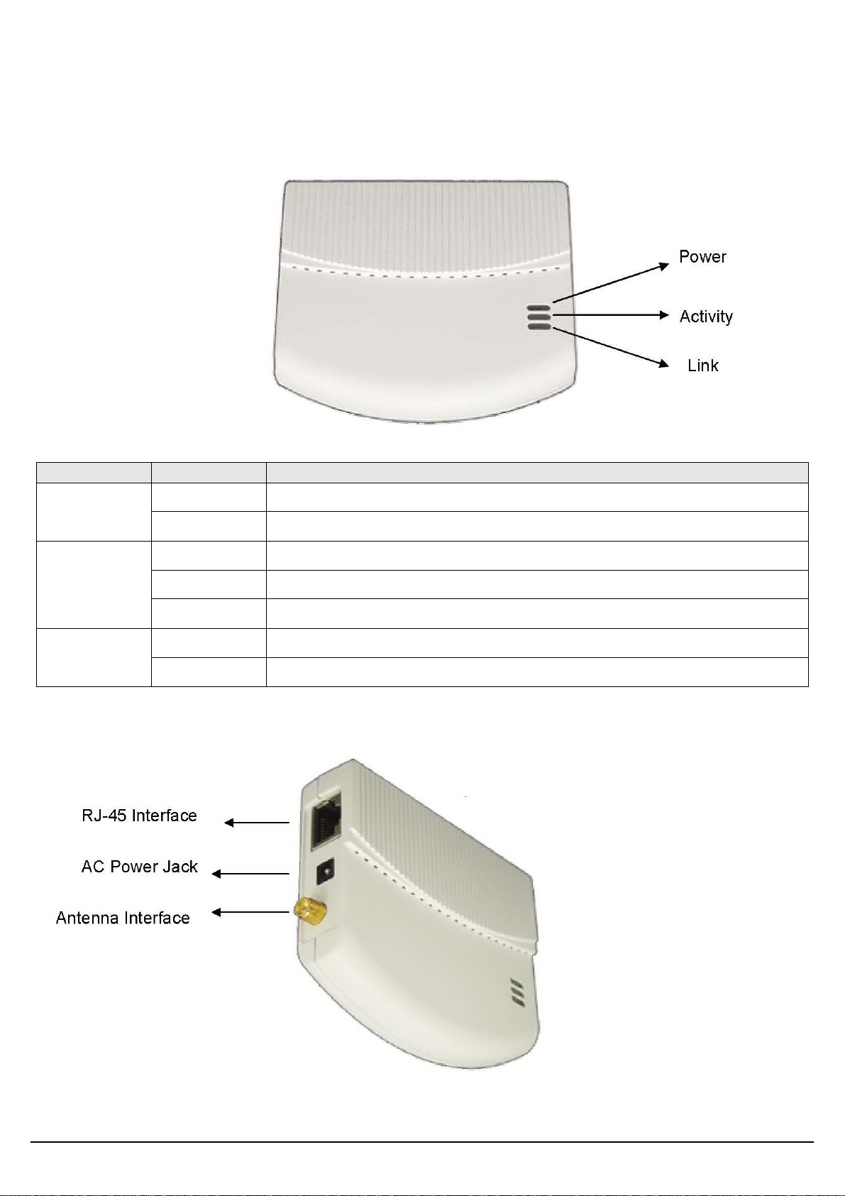
Front Panel
The front panel provides LED status of device. Refer to the following table for the meaning of each
feature.
LED Name Light Status Description
On The device is on and ready.
Power
Off The device is off.
On The device is on and ready.
Activity
Off The device is off.
Flashing The device is transmitting or receiving data.
On The device is connected to an Ethernet network.
Link
Off The device is off or there is no Ethernet connection.
Side view
User’s Guide
5
Page 7
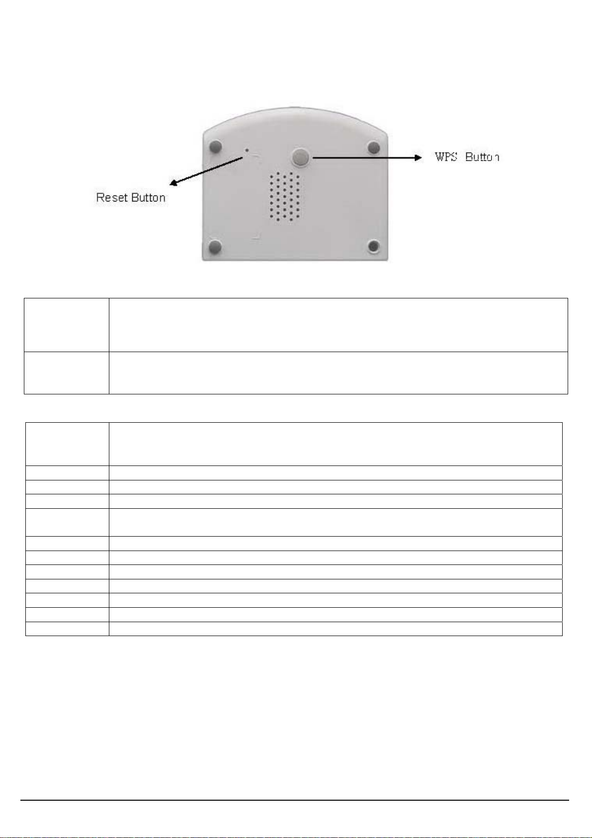
Rear Panel
The rear panel features Reset button and WPS Button. Refer to the following table for the meaning
of each feature.
Ethernet RESET/WPS Power
RESET Button
WPS Button
The RESET button can restore device to factory default settings by press this button
for approx.
Press this button to start WPS function..
Default Settings
Operation
Mode
Access Point
Router
●AP Client
User admin
Password admin
IP Address 192.168.1.250
Router Mode
IP Address
172.32.1.254
Subnet Mask 255.255.255.0
SSID SparkLAN_11N_AP
Channel 6
Mode 11b/g/n mixed mode
Encryption Disabled
WPS Function Disabled
DHCP Server Enabled
User’s Guide
6
Page 8

Hardware Installation for Connection to Your local network
1. Connect the antenna with the WCR-150GN.
2. Plug the power connection into the AC-in port on the unit, and plug the other end into a USB
interface of laptop..
3. Connect the WCR-150GN with your PC or notebook via a LAN cable.
User’s Guide
7
Page 9
4. First Time Configuration
TURN ON POWER SUPPLY
Quick power cycle would cause system corruption. When power on, be careful not to shut down in
about 5 seconds, because data is writing to the flash.
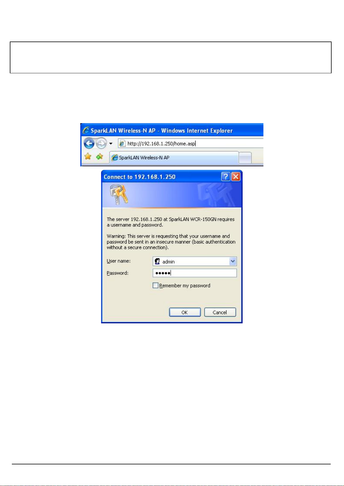
START UP & LOGIN
In order to configure the WCR-150GN, you must use web browser and manually input
http://192.168.1.250 into the Address box and press Enter. The Main Page will appear.
The configuration of this device is through web-browser. To access the configuration interfaces,
make sure you are using a computer connected to the same network as the device. The default IP
address of the device is 192.168.1.250, and the subnet-mask is 255.255.255.0. For the first time
configuration, please login with username: admin and password: admin.
Once you have logged-in as administrator, it is a good idea to change the administrator password to
ensure a secure protection to the WCR-150GN. The “Administrators Settings” can let you change the
password.
Once you have input the correct password and logged-in, the screen will change to the Setup page
screen.
User’s Guide
8
Page 10

4.1 Install Wizard
MAKE CORRECT NETWORK SETTINGS OF YOUR COMPUTER
To change the configuration, use Internet Explorer (IE) or Netscape Communicator to connect the
WEB management 192.168.1.250.
This following screen contains all of the AP's basic setup functions.
Please go to Quick Setup menu by clicking ‘Install Wizard’ button.
User’s Guide
9
Page 11
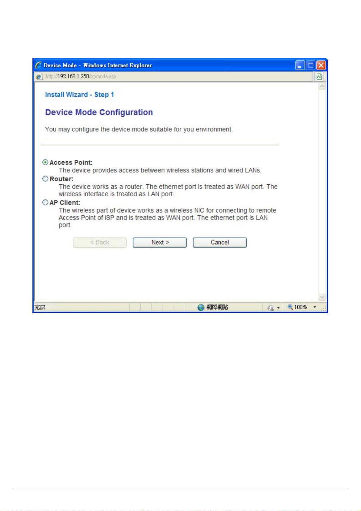
Choose the Device Operation Mode:
You can refer to Chapter 4.2 to choose the mode which you want to perform in this device.
After you finish with all settings, please click ‘Next’ button.
User’s Guide
10
Page 12

This Step is for Router Mode. If you use Access Point mode, please jump to next Step.
Wide Area Network (WAN) Settings:
Choose the Network Type your ISP provides.
You can refer to Chapter 5.1 to setup the different WAN Type.
After you finish with all settings, please click ‘Next’ button.
User’s Guide
11
Page 13
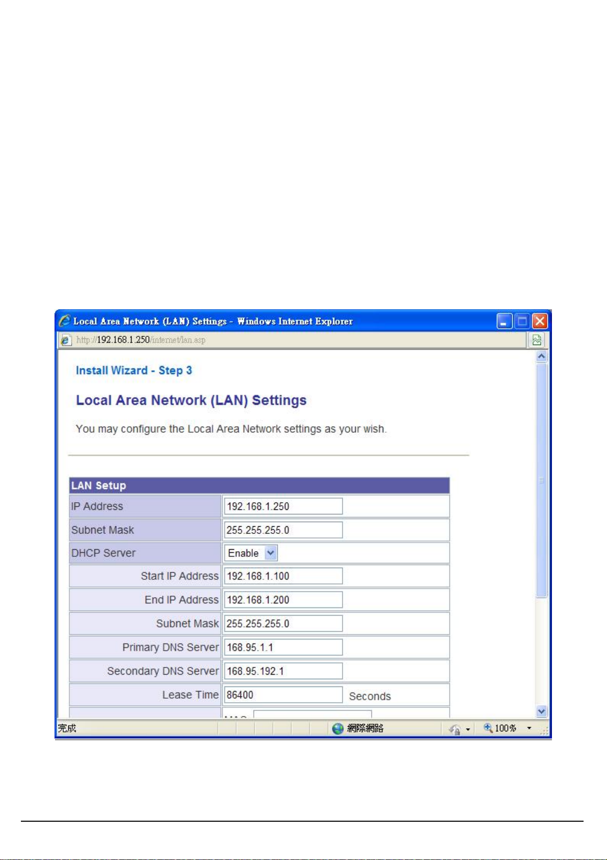
LAN Settings:
IP address:
Please input the IP address of this device.
Subnet Mask:
Please input subnet mask for this network.
DHCP Server:
If you want to activate DHCP server function of this router, select ‘Enabled’, or set it to ‘Disabled’.
Start IP Address:
Please input the start IP address of the IP range.
End IP Address:
Please input the end IP address of the IP range.
Other Settings can refer to Chapter 5.2.
After you finish with all settings, please click ‘Next’ button.
User’s Guide
12
Page 14

Basic Wireless Settings:
Radio State:
If you want to disable wireless function, please select ‘Turn OFF’.
Network mode:
Please select the radio band you want to use.
Network name (SSID):
This is the name of WCR-150GN. You can type any alphanumerical characters here, maximum 32
characters. SSID is used to identify your own wireless AP from others when there are other wireless
APs in the same area.
Hidden SSID:
This option can decide if the wireless AP will broadcast its own SSID or not. You can hide the SSID
of your WCR-150GN, so only people those who know the SSID of your WCR-150GN can get
connected.
Frequency (Channel):
You can keep the default channel setting ‘AutoSelect’ or select a channel from the dropdown list of
‘Channel’. Select one proper channel which does not employ in your environment can reduce radio
interference possibility.
After you finish with all settings, please click ‘Next’ button.
User’s Guide
13
Page 15
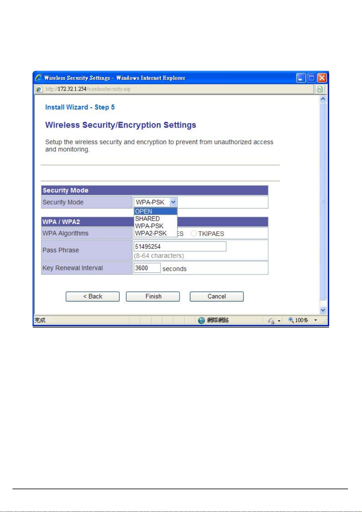
Wireless Security/Encryption Settings:
Please select an encryption method from ‘Security Mode’ dropdown menu, there are four options:
You can refer to Chapter 6.1 for the detail explaining.
After you finish with all settings, please click ‘Finish’ button.
User’s Guide
14
Page 16

4.2 Operation Mode
This device supports 3 modes for the IP network. Choose the Device Mode and click the “Apply”
button to change the modes.
Access Point: The device provides access between wireless stations and LANs. In this mode, the
Ethernet port becomes a “LAN” port.
Router: The device provides Rout er function. Choose this option, the Ethernet port will be acted as
WAN port. You can connect this port to the ADSL, cable modem or other devices for outbound
connection. At the same time, the WLAN interface will be LAN port in this operating mode.
AP Client: In this operating mode, the WLAN interface will be acted as “WAN” and “Wireless
Station (Client mode)” role. In this moment the NAT is enabled. This mode is usually used in WISP
(Wireless Internet Service Provider) application.
User’s Guide
15
Page 17

5. Internet Settings
5.1 Configuring WAN Interface
The device supports three kinds of IP configuration for WAN interface, including Static IP, DHCP
Client and PPPoE. You can select one of the WAN Access Types that depend on your ISP required.
The default WAN Access Type is “Static IP”
STATIC: You can get the IP configuration data of Static-IP from your ISP. You will need to fill the
fields of IP address, subnet mask, gateway address, and one of the DNS addresses.
Subnet Mask
User’s Guide
Item Description
The Internet Protocol (IP) address of WAN interface provided
IP Address
by your ISP or MIS. The address will be your network
identifier besides your local network.
The number used to identify the IP subnet network,
indicating whether the IP address can be recognized on the
LAN or if it must be reached through a gateway.
The IP address of Default Gateway provided by your ISP or
Default
MIS.
Gateway
Default Gateway is the intermediate network device that has
16
Page 18

knowledge of the network IDs of the other networks in the
Wide Area Network, so it can forward the packets to other
gateways until they are delivered to the one connected to the
specified destination.
The IP addresses of DNS provided by your ISP.
DNS (Domain Name Server) is used to map domain names
Primary &
Secondary DNS
to IP addresses. DNS maintain central lists of domain
name/IP addresses and map the domain names in your
Internet requests to other servers on the Internet until the
specified web site is found.
Clone device MAC address to the specify MAC address
required by your ISP.
Fill my MAC button: You can manually input the MAC
MAC Clone
Address for MAC clone, or click the button to input the MAC
Address of the PC which you are using it to configure the
device.
DHCP: All IP configuration data will obtain from the DHCP server when DHCP (Auto config) is
selected.
User’s Guide
Item Description
Clone device MAC address to the specify MAC
MAC Clone
address required by your ISP
17
Page 19

PPPoE: When the PPPoE (Point to Point Protocol over Ethernet) WAN Access Type is selected,
you must fill the fields of User Name, Password provided by your ISP. The IP configuration will be
done when the device successfully authenticates with your ISP.
Item
User Name
Password/
Verify
Password
Operation
Mode
MAC Clone
Description
The account is provided by your ISP.
The password for your account. It is required to input again in
‘Verify Password’ in order to make sure the input password is
correct.
When selecting the “Keep Alive” mode, the redial time can be
set in this field. It will redial the connection to keep it online. The
default value is 60 seconds.
On demand: When selecting the “On Demand” mode, the idle
time can be set in this field. If the network is idle more than this
time, the WAN will disconnect.
Clone device MAC address to the specify MAC address
required by your ISP
User’s Guide
18
Page 20

5.2 Configuring LAN Interface
User’s Guide
Item
IP Address
Subnet Mask
MAC Address
DHCP Server
Description
This is the IP Address for this device. You can login this
device by the IP Address via LAN or WLAN physical
interface and do any necessary configuration change.
This is the subnet mask for the LAN. The default value is
“255.255.255.0”.
The MAC Address of LAN is shown in this field.
You can select to enable DHCP server. When enabling
the DHCP server, you must setup the information below.
19
Page 21

This is the first IP Address of the IP pool which the server
Start IP Address
assigns the IP Address from.
End IP Address
Subnet mask
Primary DNS
Server
Secondary DNS
Server
Lease Time
Statically
Assigned
5.3 DHCP Client List
This is the last IP Address of the IP pool.
This is the subnet mask of this domain. The default value
is “255.255.255.0”.
This is the primary DNS server for the LAN PCs.
This is the second DNS server for the LAN PCs.
This is the DHCP lease time. When it is short, the issued
IP address to DHCP clients will be updated frequently. It
is recommended to keep default setting except for
another purpose.
You can manually assign the IP Address to the certain
PCs. Enter the MAC Address and IP Address in the table.
User’s Guide
20
Page 22

6. Wireless Settings
6.1 Access Point & Router mode
Basic
User’s Guide
Basic Settings
Item Description
Click the “Turn OFF” button to turn off the radio. Click it
Turn On/Off
again to turn on the radio.
The available options are “11b/g mixed mode”, “11b
Network Mode
only”, “11g only”, 11n only, and “11b/g/n mixed mode”.
The SSID is a unique identifier that wireless networking
Network Name
(SSID)
devices use in order to establish and maintain wireless
connectivity. Multiple access point/bridges on a network
or sub-network can use the same SSID. SSIDs are
21
Page 23

case sensitive and can contain up to 32 alphanumeric
characters.
HT Physical Mode
Item Description
Default: Mixed (Mixed, Green Field).
Mixed mode: In this mode the device transmits the
packets with preamble compatible legacy (802.11g), so
they can be decoded by legacy devices. The device
Operating Mode
Channel Bandwidth
MCS
receives and decodes both Mixed Mode packets and
legacy packets.
Green Field mode: the device transmits HT packets
without legacy compatible part. But the device receives
and decodes both Green Field and legacy packets.
This option only works when selecting Band mode in
11b/g/n mixed mode. Click the radio button to choose
between 20 MHz or 20/40MHz. This option affects the
Phy data rate of radio. Please refer to the table below
It is Modulation Coding Scheme. The available options
are “Auto, 0, 1, …, 32”. It changes the modulation of
this device and effect the maximum Physical data rate.
We recommend “Auto” setting. For the details, please
refer to the table below.
The “20/40” bandwidth mode uses 5 channels. For
example, selecting channel 7 and you can select 3 or
Extension Channel
11 for extension channel. Choose the unused channel
for the extension channel.
The table below shows the relationship among Physical data rate, Bandwidth and Guard Interval.
Data
Rate
Mbps
MCS
Bandwidth = 20MHz Bandwidth = 40MHz
Short Guard
Interval
Long Guard
Interval
Short
Guard
Interval
Long
Guard
Interval
0 (1S) 7.2 6.5 15 13.5
1 14.4 13 30 27
2 21.7 19.5 45 40.5
3 28.9 26 60 54
4 43.3 39 90 81
5 57.8 52 120 108
6 65 58.5 135 121.5
7 72.2 65 150 135
User’s Guide
22
Page 24

8 (2S) 14.4 13 30 27
9 28.9 26 60 54
10 43.3 39 90 81
11 57.8 52 120 108
12 86.7 78 180 162
13 115.6 104 240 216
14 130 117 270 243
15 144.4 130 300 270
32 Not
Supported
Not
Supported
6.7 6
MCS: Modulation Coding Scheme
MCS=0~7 (1S, One Tx Stream)
MCS=8~15 (2S, Two Tx Stream)
MCS 32: BPSK
User’s Guide
23
Page 25

Security
Wireless Security/Encryption Settings
Wireless Security/Encryption Settings
Item Description
Security Mode
OPEN, SHARED, WPA-PSK, WPA2-PSK
The available options are shown according to the numbers of the BSSID in the Basic Setting. Each
SSID can setup different encryption type. For example, set up 4 BSSID and 4 sets of security
shows on this page:
Security Mode: Choose one as the wireless authentication among the following types: OPEN,
SHARED, WPA-PSK,, WPA2-PSK
Encryption Type: Select one for the encryption type. The options vary depending on the
Authentication mode. The corresponding options shows below.
Authentication
Open/Shared/WEP
Encryption
type
Key option
Default Key ID, Key content of Key
WEP
Auto
1/2/3/4
User’s Guide
WPA/WPA2-PSK
(Pre-Shared Key)
TKIP, AES,
Pass Phrase (8-64 characters),
TKIP/AES
Key Renewal Interval
(both)
24
Page 26

WEP Encryption Setting
Wired Equivalent Privacy (WEP) is implemented in this device to prevent unauthorized access to
your wireless network. The WEP setting must be as same as each client in your wireless network.
Authentication Type: Open, Shared and Auto. When choose “Open” or “Shared”, all of the
clients must select the same authentication to associate this AP. If select “WEP Auto”, the clients
don’t have to use the same “Open” or “Shared” authentication. They can choose any one to
authenticate.
Default Key ID: Select whether the Key ID as the default Key.
Key 1/2/3/4: Select “ASCII” or “Hex” and then type the key in the text field.
64-bit WEP Encryption:64-bit WEP keys are as same as the encryption method of 40-bit WEP.
When input 10 hexadecimal digits (0-9, a-f or A-F) or 5 ACSII chars as the key, it is using 64-bit
WEP encryption.
128-bit WEP Encryption:128-bit WEP keys are as same as the encryption method of 104-bit
WEP. When input 26 hexadecimal digits (0-9, a-f or A-F) or 13 ACSII chars, it is using 128-bit
WEP encryption.
WPA/WPA2-PSK:
Pass Phrase:
Option: Pass Phrase (8-64 characters). This mode requires only an access point and client station
that supports WPA-PSK. The WPA-PSK settings include Key Format, Length and Value. They
must be as same as each wireless client in your wireless network. When Key format is
Passphrase, the key value should have 8-64 ACSII characters.
Key Renewal Interval:
The WPA Algorithm will regroup the key for a period. The default value is 3600 seconds and you
can adjust the time interval.
Access Policy
For each SSID, the Access Policy can be selected and setup. The policy includes “Reject” and
“Allow”. The Reject policy rejects the station according to the MAC table in the policy configuration,
and let the other stations to connect. The allow policy performs reversely.
Add a station MAC: Key in station MAC Address in the text field. The valid format of the MAC
Address should be “xx:xx:xx:xx:xx:xx”. The station MAC Address can be found on the label or
configure utility of the WLAN card. For deleting one record in the table, click the “Del” button of the
record.
User’s Guide
25
Page 27

WPS
This function helps to establish the Wi-Fi security. For AP mode, it can be setup one WPS method
including PIN (Personal Identification Number) and PBC (Push Button Communication).
To begin the WPS progress, the WLAN security must be setup first. Please setup one among
WPAPSK, WPA2PSK and then apply WPS setting.
PIN: query the PIN code in the utility of WLAN client, and then enter it in the PIN field. The Wi-Fi
link between the WLAN client and the device should be encrypted.
User’s Guide
26
Page 28

PBC: Select PBC, and then you can begin the PBC process. Press the PBC button in the rear
panel can also trigger this process. Press or click the PBC button on the WLAN client to finish the
communication. You can press the PBC button on the WLAN client first and then click the PBC
button on this device to establish the encryption.
The options and the information fields are shown below.
WPS Config
Item Description
Through drop-down manual to enable / disable this
WPS
function.
WPS Summary
Item Description
WPS Current Status
WPS Configured
WPS SSID
It shows the current status of the WPS process.
It indicated whether the WPS is configured.
It is the SSID of this device.
It indicates the authenticate mode of this device. It can
WPS Auth Mode
be configured in the wireless security page.
It indicates the encryption method of this device. Like
WPS Encryption
WPS authentication mode, it can be configured in the
Type
wireless security page.
AP PIN
Auto WPS Settings
It shows the current PIN number of this device.
Press this button to setup the WPS of this device.
WPS Progress
Item Description
Choose to use PIN (Personal Identification Number) or
WPS mode
PBC (Push Button Communication).
User’s Guide
PIN
Input the 8-digits PIN of client.
27
Page 29

Wireless Status
Item
Mode
Band
SSID
Channel
Rate
Security
BSSID
Wireless Station
List
Description
This is the wireless mode for the device such as AP,
client mode.
It shows the current radio mode such as “B/G/N”,
“B/G”, “B only” and “G only”.
It shows the SSID of this device.
It shows the current channel of the radio.
The data rate of this device.
It indicates the encryption type for the radio.
It is the current BSSID of the radio. In this device, it
is also the MAC Address of the WLAN interface.
The number of associated WLAN clients show in this
field.
User’s Guide
28
Page 30

Site Survey
In the Site Survey, the information of nearby APs will be shown here.
User’s Guide
29
Page 31

6.2 AP Client mode
Profile
In the first page, you can see the profile list to show the information including Profile name, SSID,
Network Type, Power Saving Mode, RTS Threshold, Fragment Threshold. Use four buttons to
manage the profile list. The “Add” button is to add a new profile. The “Delete” button is to delete
the selected profile. The “Edit” button is to edit the selected profile. The “Activate” button is to
enable the selected button, so this device will associate to the AP according to the profile.
User’s Guide
30
Page 32

System Configuration
Item Description
Profile Name
SSID
Enter your profile name.
Enter the SSID of the AP or Ad Hoc network.
Choose one between “802.11Ad Hoc” and
Network Type
Infrastructure.
For the Infrastructure network, this device can be setup
Power Saving Mode
to CAM (Constantly Awake Mode) or Power Saving
Mode.
Check the box to setup the RTS Threshold. The default
RTS Threshold
value is 2347 and the available range is from 0 to 2432.
Check the box to setup the Fragment Threshold. The
Fragment Threshold
default value is 2346 and the available range is from
256 to 2432.
Security Policy
Item Description
Please choose the encryption method. The available
Security Mode
options are OPEN, SHARED, WPA-Personal and
WPA2-Personal.
Wire Equivalence Protection (WEP)
Item Description
WEP Key Length
WEP Key Entry
Method
Choose to use 64bit or 128bit length of key.
Select the key type. The available options are ASCII
Text or Hexadecimal.
For WEP key, please input the key1-4. The key text and
WEP Keys
Default Key
the length must match the above settings.
Select the default Tx WEP key.
User’s Guide
31
Page 33

Link Status
The status of the radio shows in this field.
User’s Guide
32
Page 34

Site Survey
Site Survey
Item Description
Check the radio button in front of the SSID and click
Connect
Rescan
“Connect” button to connect.
Click this button to refresh the list.
Check the radio button in front of the SSID and click
Add Profile
“Add Profile” to add the SSID to the profile.
User’s Guide
33
Page 35

Statistics
User’s Guide
34
Page 36

Advanced
Advanced Configuration
Item Description
Wireless Mode
(Infrastructure)
Choose the proper Wireless Mode to connect remote
AP which provided by your WISP.
HT Physical Mode
Item Description
MM (Mixed Mode) or GF (Green Field).
Mixed mode: In this mode the device transmits the
packets with preamble compatible legacy (802.11g), so
they can be decoded by legacy devices. The device
HT Physical Mode
receives and decodes both Mixed Mode packets and
(High throughput)
legacy packets.
Green Field mode: the device transmits HT packets
Channel Bandwidth
User’s Guide
MCS (Modulation
Coding Scheme)
without legacy compatible part. But the device receives
and decodes both Green Field and legacy packets.
Choose “20” for the standard bandwidth or “Auto” to
use the 40MHz bandwidth automatically.
Choose MCS. Please refer to the section of Access
Point.
35
Page 37

WPS
The WPS AP lists in the top of the page. The bottom panel shows the status of WPS.
Please refer to the section 6.1, WPS section of Access Point mode for the operation.
WPS configuration
Item Description
Refresh
Click this button to refresh the WPS AP list.
This device supports Enrollee and Registrar in AP
Mode
Client mode.
This is the PIN code for PIN communication. Click
PIN
PIN Start
PBC Start
Cancel
“Renew PIN” to generate a new PIN code.
Click this button to start PIN process.
Click this button to start PBC communication.
Click this button to cancel the establishing WPS link.
Click this button to discard current PIN and generate a
Renew PIN
new PIN code.
Registrar Mode can let you change the AP, which you connect, information as below.
User’s Guide
36
Page 38

Registrar Settings
Item Description
SSID
Authentication
Encryption
Key
The SSID that you want to change
WPA-PSK, WPA2-PSK
TKIPP, AES
Pass Phrase (8-64 characters), Key Renewal Interval
User’s Guide
37
Page 39

7. Firewall
7.1 DMZ
A De-Militarized Zone is used to provide Internet services without sacrificing unauthorized access
to its local private network. Typically, the DMZ host contains devices accessible to Internet traffic,
such as Web (HTTP) servers, FTP servers, SMTP (e-mail) servers and DNS servers. So that all
inbound packets will be redirected to the computer you set. Generally it is not recommended to
setup DMZ due to fully exposed the PC/server to the Internet, but for some application using
uncertain incoming ports such as Internet games, it is could be useful to setup DMZ for the
application.
User’s Guide
Item Description
DMZ Settings
DMZ IP Address
Enable this setting, and then click “Apply” button to
save the changes.
Input the IP Address of the computer that you want
to expose to Internet.
38
Page 40

8. Administration
8.1 Management
User’s Guide
Item Description
Enter the name for login. The default name is
Account
“admin”.
Enter the password for login. The default password
Password
is “admin”.
39
Page 41

8.2 Firmware Update
This page provides the firmware update function. Click the browse button to browse the file and click
“open” button to select the file. The update process takes about 1 minute and do not power off the
device during this period.
User’s Guide
Item Description
Browse
Apply
Click the “Browse” to choose the Firmware.
Click to start update Firmware.
40
Page 42

8.3 Settings Management
In this page, you can export the setting, import the setting or load the factory default.
Item Description
To export the settings, click “Export” button to save
the configuration. In the pop up window, click “Open”
Export Settings
to open the configuration. You can read the
configuration in the next page. Click “Save” to save
the configuration file. The file extension is “.dat”.
To import the settings, click “Browse” to browse the
Import Settings
Load Factory
Defaults
file, and then click “Import” to import the setting file.
Click “Load Default” button to reset the device to
factory default. All users’ settings will be erased.
User’s Guide
41
Page 43

8.4 Status
System Info
Item Description
Firmware Version
System Up Time
Device Mode
Internet Configurations
Item
Connected Type
WAN IP Address
Subnet Mask
Default Gateway
Primary Domain
Name Server
It shows the version of firmware on this device.
It indicates the time on this device. If the NTP client
is enabled, the time will sync with the NTP server.
It shows the operation mode of this device.
Description
It shows the WAN type information such as DHCP,
Static IP, PPPoE, etc.
It shows the IP Address of the WAN interface.
This is subnet mask of the WAN interface.
It is the default gateway of WAN interface.
It shows the primary DNS server.
User’s Guide
Secondary
Domain Name
It shows the current secondary DNS server.
42
Page 44

Server
MAC Address
Local Network
Local IP Address
Local Netmask
MAC Address
8.5 Statistics
This is the MAC Address of the WAN interface.
Item Description
This is the IP Address of the LAN interface.
This is the Netmask for the LAN.
This is the MAC Address of the LAN interface.
Memory
Item
Memory total
Memory left
This is the total memory size for this device.
The available memory size shows in this field.
Description
WAN/LAN
The information shows packet accumulation during each interface transmission
WLAN
The information shows packet accumulation during WLAN transmission
User’s Guide
43
Page 45

9. Troubleshooting – Q & A
1. I’m trying to log on the AP’s Web configuration page, but I do not see the login screen.
Answer:
1. Please make sure the IP address that you input on address field of IE browser is correct.
2. Make sure the physical layer connection is established. If you are using wired to connect this AP,
check the relevant LAN LED whether is lit or not.
3. On Command Prompt screen, using “ ping “ command to probe this AP, check if you got reply
from it.
Command: ping < Destination IP address >
4. If you have any TCP/IP setting problem, please refer to the Quick Installation Guide.
2. I forgot my password, how to log on this AP for configuration?
Answer:
1. Reset the AP to factory default by pressing the Reset button for 10 seconds then releasing it.
2. Log on the AP’s web management by http://192.168.1.250
Enter the username “admin” and enter the default password “admin”.
3. How to set the AP to factory default setting.
Answer:
1. Reset the AP to factory default by pressing the Reset button for 10 seconds then releasing it.
2. After release the Reset button, the AP will get back all setting to factory default and reboot
system.
3. While the reboot is complete, log on the AP’s web management by default IP
http://192.168.1.250
Enter the username “admin” and enter the default password “admin”.
4. My AP will not turn on. No LED’s light up.
Answer:
Usually it is caused by the power is not connected.
Please double check the power adapter if it connected to your AP and the other side is plugged into
the power outlet.
If it still has no power, please contact your reseller.
5. I can’t access the AP from a wireless client.
Answer:
Generally to make the wireless client unable to access AP with following possible issues:
1. Settings are different among each wireless station.
2. Out of range.
3. Wrong security key.
Resolution:
User’s Guide
44
Page 46

Make sure that mode, SSID, Channel and encryption settings are set the same on each wireless
adapter. Make sure that your computer is within range and free from any strong electrical devices
that may cause interference.
6. What devices cause interference?
Answer:
The AP is operating in the unlicensed 2.4 GHz band. Other devices operate in this frequency range
that may cause interference include microwave ovens and 2.4 GHz portable phones. PCs or analog
cellular phones do not operate at 2.4 GHz and do not cause interference. Proper placement of
access points usually eliminates interference problems created by other 2.4 GHz devices.
User’s Guide
45
Page 47

EC Declaration of Conformity
Name applicant:
Sparklan Communications, Inc.
8F #257, Sec 2, Tiding Blvd,
Neihu District, (11493)
Taipei, Taiwan
Hereby declares under sole responsibility that product
Brand name: Sparklan
Product number: WCR-150GN/WAPR-150GN
Product description: 802.11bgn smart client/802.11bgn AP
To which this declaration relates complies with the requirements o f the following standards:
EN 300 328 V1.7.1 (2006-10)
EN 301 489-1 V1.8.1(2008-04)
EN 301 489-17 V2.1.1(2009-05)
EN 50385 (2002-08)
EN 60950-1: 2006
This certifies that the designated product as described above complies with the directives described
above and carries the CE marking accordingly.
This declaration has been signed under responsibility of the manufacturer / importer.
This document is only valid in connection with the test report no.:
RE990429C04,RM990429C04,SE990429C04,LD990429C04
Test laboratory: Advanced Data Technology Corporation
Lab Address: No. 47, 14th Ling, Chia Pau Tsuen, Linko Hsiang 244, Taipei Hsien, Taiwan. ROC
Name manufacturer / importer:
Sparklan Communications, Inc.
May 3, 2010 Mike Chen
President
Page 48

Federal Communication Commission Interference Statement
This equipment has been tested and found to comply with the limits for a Class B digital
device, pursuant to Part 15 of the FCC Rules. These limits are designed to provide
reasonable protection against harmful interference in a residential installation. This
equipment generates, uses and can radiate radio frequency energy and, if not
installed and used in accordance with the instructions, may cause harmful interference
to radio communications. However, there is no guarantee that interference will not
occur in a particular installation. If this equipment does cause harmful interference to
radio or television reception, which can be determined by turning the equipment off
and on, the user is encouraged to try to correct the interference by one of the following
measures:
- Reorient or relocate the receiving antenna.
- Increase the separation between the equipment and receiver.
- Connect the equipment into an outlet on a circuit different from that to which the
receiver is connected.
- Consult the dealer or an experienced radio/TV technician for help.
FCC Caution: Any changes or modifications not expressly approved by the party
responsible for compliance could void the user's authority to operate this equipment.
This device complies with Part 15 of the FCC Rules. Operation is subject to the following
two conditions: (1) This device may not cause harmful interference, and (2) this device
must accept any interference received, including interference that may cause
undesired operation.
IMPORTANT NOTE:
FCC Radiation Exposure Statement:
This equipment complies with FCC radiation exposure limits set forth for an uncontrolled
environment. This equipment should be installed and operated with minimum distance
20cm between the radiator & your body.
This transmitter must not be co-located or operating in conjunction with any other
antenna or transmitter.
The availability of some specific channels and/or operational frequency bands are
country dependent and are firmware programmed at the factory to match the
intended destination. The firmware setting is not accessible by the end user.
Page 49

NCC statement:
經型式認證合格之低功率射頻電機,非經許可,公司、商號或使用者均不得擅自變更頻率、加大功
率或變更原設計之特性及功能。
低功率射頻電機之使用不得影響飛航安全及干擾合法通信;經發現有干擾現象時,應立即停用,並
改善至無干擾時方得繼續使用。前項合法通信,指依電信法規定作業之無線電通信。低功率射頻電
機須忍受合法通信或工業、科學及醫療用電波輻射性電機設備之干擾。
 Loading...