

Page 1

WLAN Outdoor Bridge
User Manual
Version 1.0
Page 2

Table of Contents
PREFACE................................................................................................................................ 1
1. OUTDOOR AP INSTALLATION ......................................................................................... 4
Packing List.........................................................................................................................................................4
Hardware Installation ........................................................................................................................................5
2. FIRST TIME CONFIGURATION......................................................................................... 8
Before Start to Configure ..................................................................................................................................8
Advanced Settings .......................................................................................................................................... 34
Configuring Wireless Security ....................................................................................................................... 37
Configuring Universal Repeater .................................................................................................................... 43
3. CONFIGURING WDS....................................................................................................... 45
WDS Application.............................................................................................................................................. 49
4 ADVANCED CONFIGURATIONS...................................................................................... 51
Configuring LAN to WAN Firewall.................................................................................................................. 51
Port Filtering..................................................................................................................................................... 51
IP Filtering ........................................................................................................................................................ 51
MAC Filtering.................................................................................................................................................... 52
Configuring Port Forwarding (Virtual Server) .............................................................................................. 52
Multiple Servers behind NAT Example:........................................................................................................ 53
Configuring DMZ.............................................................................................................................................. 53
Configuring WAN Interface ............................................................................................................................ 54
Static IP............................................................................................................................................................. 55
DHCP Client (Dynamic IP) .............................................................................................................................. 56
PPPoE................................................................................................................................................................ 57
PPTP.................................................................................................................................................................. 58
Configuring Clone MAC Address ................................................................................................................... 59
Configuring DHCP Server ............................................................................................................................... 61
Bandwidth Control........................................................................................................................................... 62
QoS (Quality of Service).................................................................................................................................. 63
Dynamic Route Setup..................................................................................................................................... 68
VPN Pass-through............................................................................................................................................ 69
Using CLI Menu................................................................................................................................................ 70
SNMP Agent ......................................................................................................................................................71
Firmware Upgrade............................................................................................................................................74
Configuration Data Backup & Restore......................................................................................................... 75
Auto Discovery Tool ................................................................................................................................... 75
Page 3

Preface
This guide is for the networking professional who installs and manages
the outdoor product hereafter referred to as the “device”. To use this guide,
you should have experience working with the TCP/IP configuration and be
familiar with the concepts and terminology of wireless local area networks.
1
Page 4

Certification Declaration
FCC Radiation Norm
Federal Communication Commission Interference Statement
This equipment has been tested and found to comply with the limits for a
Class B digital device, pursuant to Part 15 of the FCC Rules. These limits are
designed to provide reasonable protection against harmful interference in a
residential installation. This equipment generates, uses and can radiate
radio frequency energy and, if not installed and used in accordance with the
instructions, may cause harmful interference to radio communications.
However, there is no guarantee that interference will not occur in a
particular installation. If this equipment does cause harmful interference
to radio or television reception, which can be determined by turning the
equipment off and on, the user is encouraged to try to correct the
interference by one of the following measures:
- Reorient or relocate the receiving antenna.
- Increase the separation between the equipment and receiver.
- Connect the equipment into an outlet on a circuit different from that to
which the receiver is connected.
- Consult the dealer or an experienced radio/TV technician for help.
FCC Caution: Any changes or modifications not expressly approved by the
party responsible for compliance could void the user's authority to operate
this equipment.
This device complies with Part 15 of the FCC Rules. Operation is subject to
the following two conditions: (1) This device may not cause harmful
interference, and (2) this device must accept any interference received,
including interference that may cause undesired operation.
This transmitter must not be co-located or operating in conjunction with any
other antenna or transmitter.
IMPORTANT NOTE: FCC Radiation Exposure Statement: This equipment
complies with FCC radiation exposure limits set forth for an uncontrolled
environment. In order to avoid the possibility of exceeding the FCC radio
frequency exposure limits, human proximity to the antenna shall not be less
than 20cm (8 inches) during normal.
2
Page 5

CE Radiation Norm
FCC & CE Compliance Statement
CAUTION!
This equipment has been tested and found to comply with the limits of
the European Council Directive 99/5/EC on the approximation of the law of
the member states relating to EN 300 328, EN 301 489-1, EN 301 489-17
and EN60950.
These limits are designed to provide reasonable protection against radio
interference in a residential environment. This equipment can generates, uses
and radiate radio frequency energy and, if not installed and used in
accordance with the instructions, may cause harmful interference to radio
communications.
However, there is no guarantee that interference will not occur in a
particular installation. If this equipment does cause harmful interference to
radio or television reception, which is found by turning the equipment ON and
OFF, the user is encouraged to try to reduce the interference by one or more of
the following measures:
x Reorient or relocate the receiving antenna
x Increase the separation between the equipment and the receiver
x Connect the equipment into an outlet on a circuit different from that to
which the receiver is connect to
x Consult a dealer or an experienced technician for assistance
The Federal Communication Commission warns the user that changes or
modifications to the unit not expressly approved by the party responsible for
compliance could void the user’s authority to operate the equipment.
3
Page 6

1. Outdoor AP Installation
Packing List
Before you start to install the ODU, make sure the package contains the
following itemsΚ
ɿ Wireless Outdoor Bridge unit * 1
ɿ Mounting Kit * 1
ɿ Waterproof (IP67) RJ-45 Cable (30M) * 1
ɿ Waterproof (IP66) RF Cable (1M) * 1
ɿ Power Over Ethernet Kit * 1
ɿ Ground Wire * 1
ɿ 2.5” /4” U bolts * 2 and Anchor * 4
ɿ 6 dBi omni directional antenna * 1 (separated package)
ɿ RJ-45 Cable (1.5M) * 1
4
Page 7
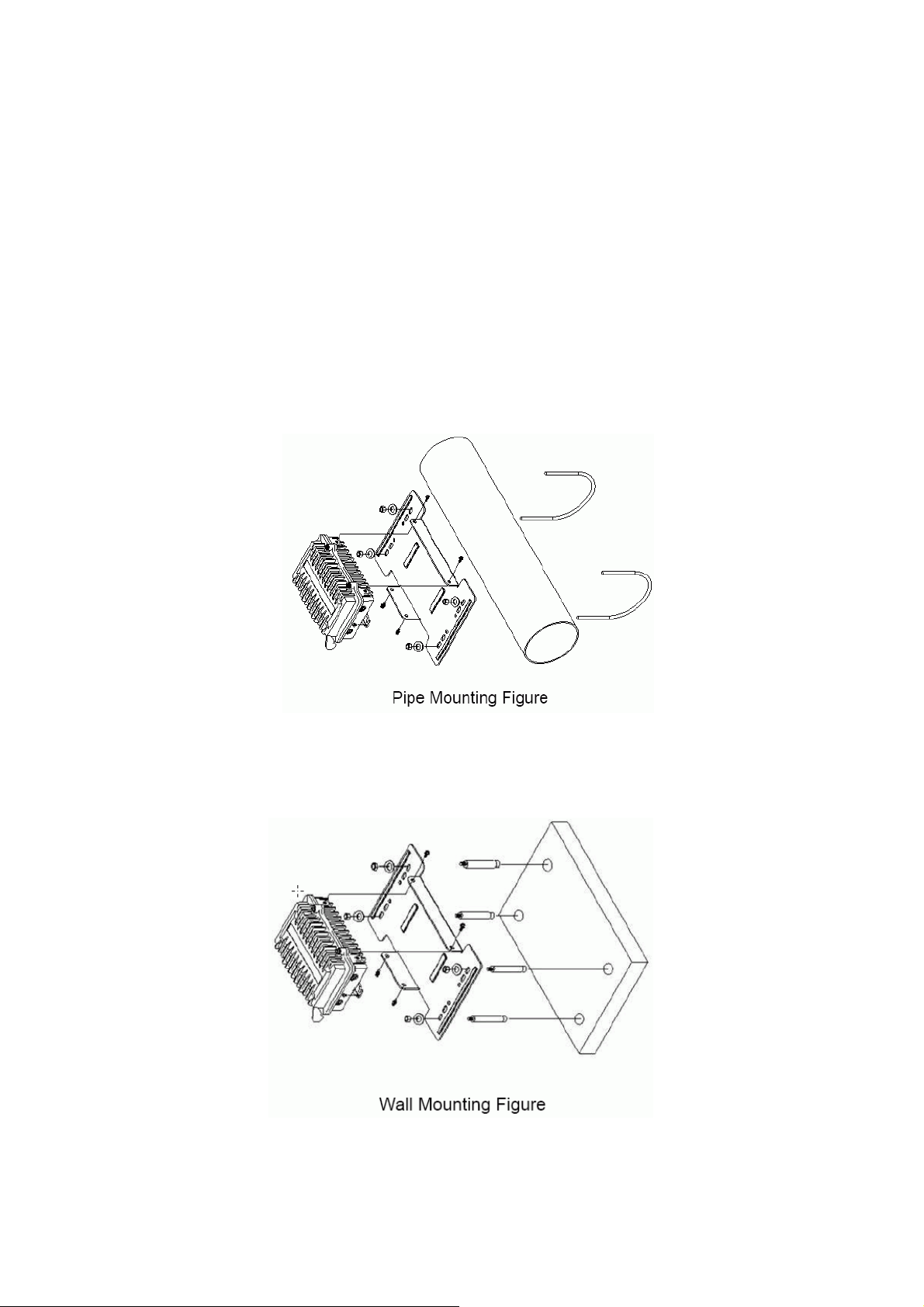
Hardware Installation
Note: ALL the 4 screws had been tightened onto the ODU and Bracket
Once you check off everything from the package, you can start to install the
ODU. You can mount to a pipe, a pole or to the side of a building. The steps are
showed in the followingΚ
1. You must mount the ODU into the bracket first.
2. You can use the 2 or 4 inches U bolt to mount on the pipe, depending on
the radius of the pipe. (Wall mounting is referred to Wall Mounting Figure) The
two U bolts must be mounted tightly. Be aware of not over-tight the U bolt.
5
Page 8
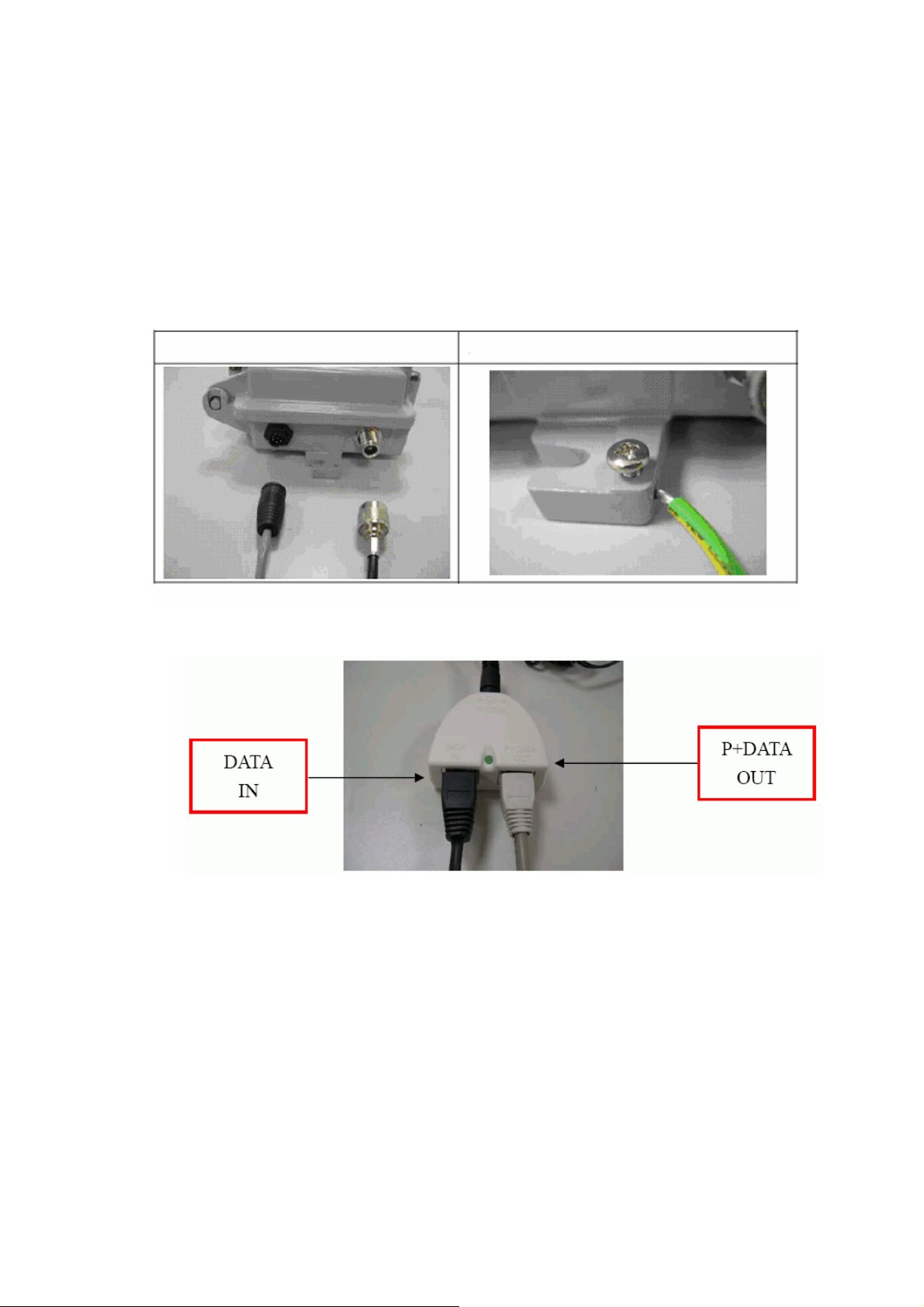
3.. After checking the ODU is mounted well, you can connect the following
Caution: DON’T plug the power cord into PoE device before you finish install
the antenna and Ground wire to ensure the safety.
two cables: the Waterproof RJ-45 network cable to “P+ DATA OUT” port of ODU
and the RF cable to antenna port. Additional waterproof tool, such as
waterproof tape, is recommended to use to enhance the waterproof function.
It is suggested to have a lightening protector between antenna and antenna
port. Connecting the ground wire as the figure of “ODU ground wire
connection.”
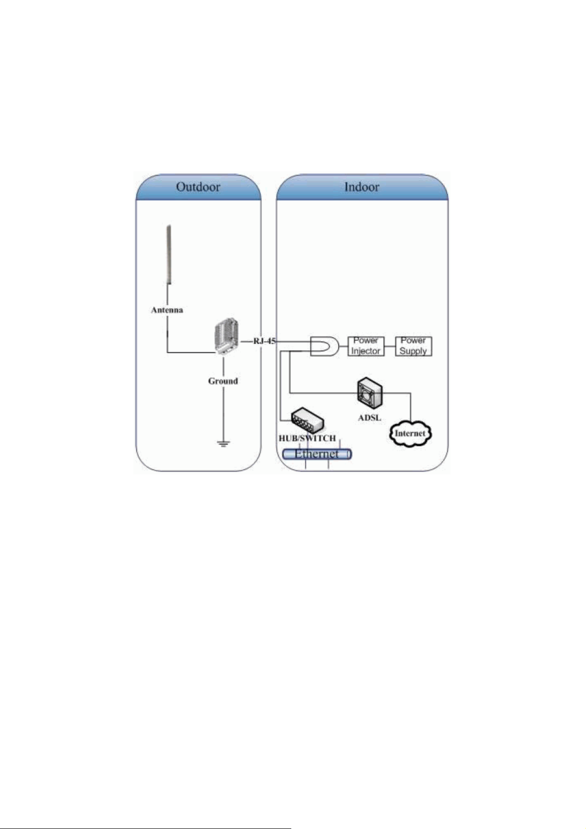
4. Plug the other end of the waterproof RJ-45 cable to the PoE device. The
PoE device is guaranteed only in indoor environment.
If the RJ-45 cable’s length is not long enough to connect to your
network
device for indoor parts installation, you can extend the cable length.
However, make sure the maximum length of the RJ-45 cable is shorter
than
100M (about 109 yards) for normal operation under IEEE 802.3ʳstandards.
When you plug the regular RJ-45 cable into the PoE device, you should use
the regular RJ-45 cable to plug into the “DATA IN” of “Power Over Ethernet
Kit” to connect to hub/switch or use the crosslink RJ-45 cable (Not included
in the Packing List) to connect with user’s PC
The waterproof RJ-45 cable must be connected to the “P+DATA OUT” port.
6
Page 9
Caution:Be careful! Don’t plug the two cables inversely. It will damage the
devices
We recommend you refer to the following illustration as a guideline for
hardware installation.
7
Page 10

2. First Time Configuration
Before Start to Configure
There are two ways to configure the device, one is through web-browser,
and the other is through Secure Shell CLI interface. To access the
configuration interfaces, make sure you are using a computer connected to
the same network as the device. The default IP address of the device is
192.168.2.254, and the subnet-mask is 255.255.255.0.
The device has three operation modes (Router/Bridge/WISP). In bridge
mode, also known as AP Client, you can access the device by both WLAN
(Wireless Local Area Network) and wired LAN. And in router/WISP modes,
the device can be accessed by both WLAN and WAN. The default IP
addresses for the device are 192.168.2.254(for LAN), 172.1.1.1(for WAN),
so you need to make sure the IP address of your PC is in the same subnet as
the device, such as 192.168.2.X (for LAN), 172.1.1.X (for WAN).
Please note that the DHCP server inside the device is default to up and
running. Do not have multiple DHCP servers in your network environment,
otherwise it will cause abnormal situation.
We also provide an auto-discovery tool which is for finding out the IP of
the device. In case, you’ve forgot the IP of the device or the IP of the device
has been changed, you can use the tool to find out the IP of the device even
your PC is not in the same subnet as the device is.
Knowing the Network Application
OUTDOOR AP can act as the following roles, and it supports WDS (Wireless
Distribution System) function.
ɿ Access Point
ɿ ʳʳʳWDS (Wireless Repeater)
ɿ Bridge/Router
ɿ WISP
ɿ AP Client
The device provides 3 different operation modes and the wireless radio of
device can act as AP/Client/WDS. The operation mode is about the
communication mechanism between the wired Ethernet NIC and wireless
NIC, the following is theʳtypes of operation mode.
8
Page 11

Router
Bridge
WISP (Wireless ISP)
AP (Access Point
AP Client
WDS (Wireless Distribution System)
The wired Ethernet (WAN) port is used to connect with ADSL/Cable
modem and the wireless NIC is used for your private WLAN. The NAT is
existed between the 2
NIC and all the wireless clients share the same public IP address through the
WAN port to ISP. The default IP configuration for WAN port is static IP. You
can access the web server of device through the default WAN IP address
172.1.1.1 and modify the setting base on your ISP requirement.
The wired Ethernet and wireless NIC are bridged together. Once the mode
is selected, all the WAN related functions will be disabled.
This mode can let you access the AP of your wireless ISP and share the
same public IP address form your ISP to the PCs connecting with the wired
Ethernet port of the device. To use this mode, first you must set the wireless
radio to be client mode and connect to the AP of your ISP then you can
configure the WAN IP configuration to meet your ISP requirement.
The wireless radio of the device acts as the following roles.
)
he wireless radio of device serves as communications “hub” for wireless
clients and provides a connection to a wired LAN.
This mode provides the capability to connect with the other AP using
infrastructure/Ad-hoc networking types. With bridge operation mode, you
can directly connect the wired Ethernet port to your PC and the device
becomes a wireless adapter. And with WISP operation mode, you can
connect the wired Ethernet port to a hub/switch and all the PCs connecting
with hub/switch can share the same public IP address from your ISP.
This mode serves as a wireless repeater; the device forwards the packets
to another AP with WDS function. When this mode is selected, all the
wireless clients can’t survey and connect to the device. The device only
allows the WDS connection.
9
Page 12
WDS+AP
This mode combines WDS plus AP modes, it not only allows WDS
connections butʳalso the wireless clients can survey and connect to the
device.
The following table shows the supporting combination of operation and
wireless radio modes.
Bridge Router WISP
AP V V X
WDS V V X
Client V X V
AP+WDS V V X
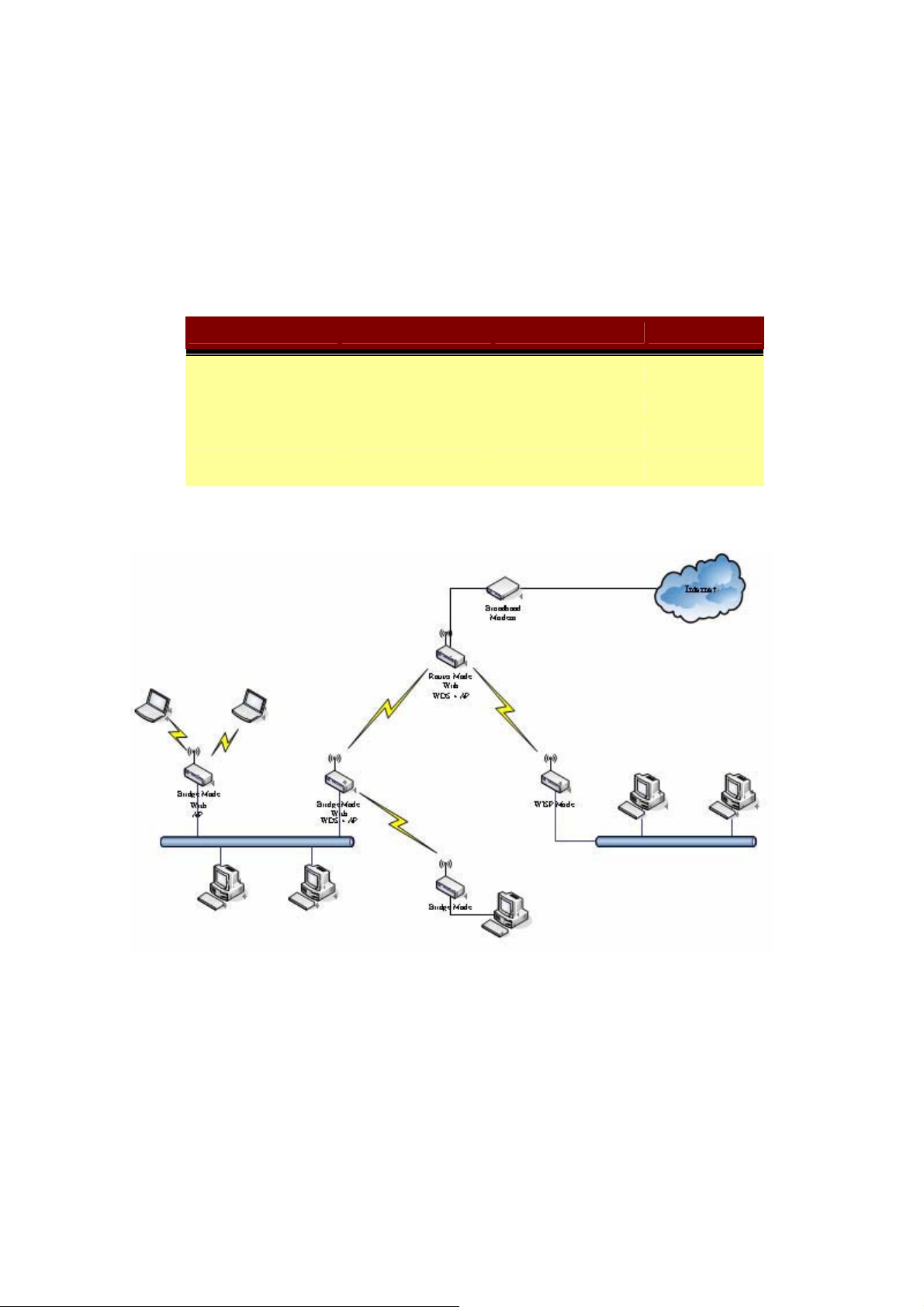
Hereafter are some topologies of network application for your reference.
10
Page 13
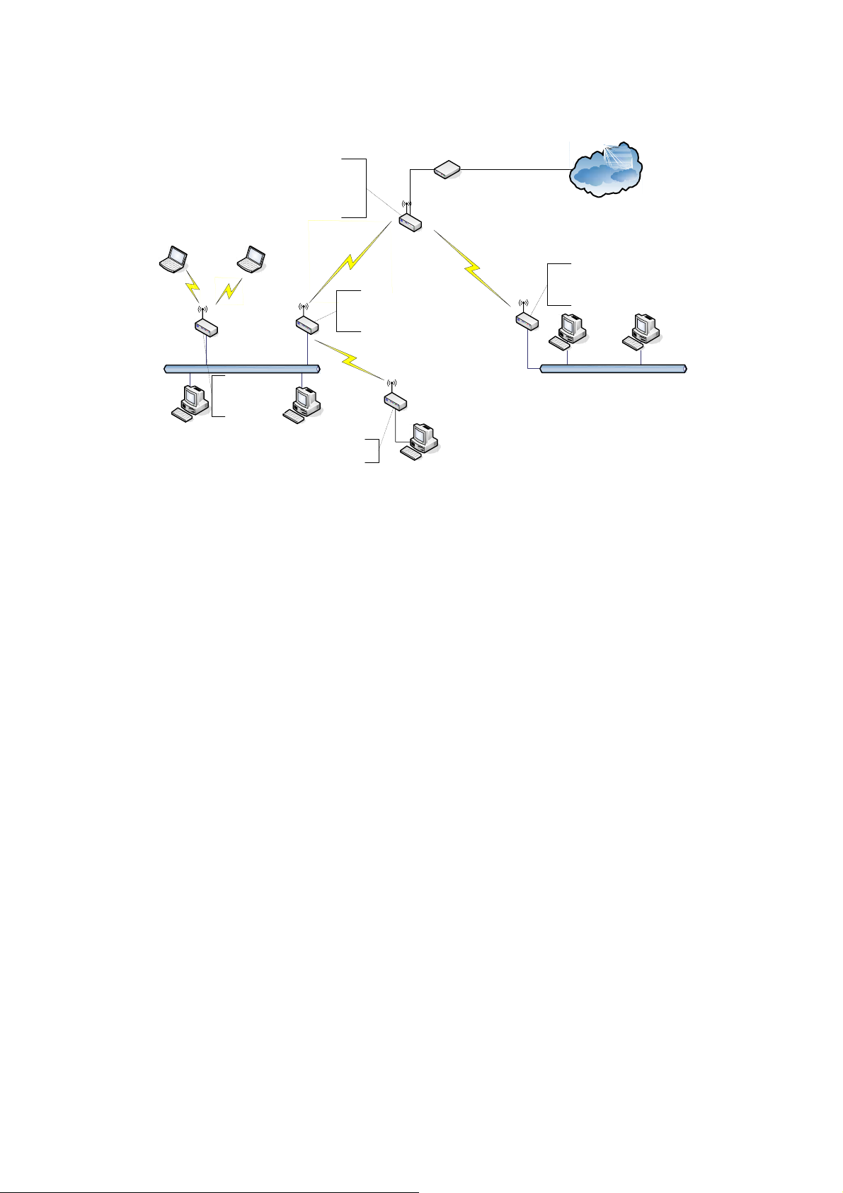
Examples of Configuration
This example demonstrates how to set up a network with different device
configurations. There are 2 DHCP servers (DEV1/DEV4) in the network to
control the IP configuration of 2 domains (192.168.2.x/192.168.3.x). Once
the setting is done, all the PCs can visit Internet through DEV1.
We assume all the devices keep the factory default setting. To make sure
that user can continuing press the rest button for more than 5 seconds to
restore the factory default setting.
The following descriptions show the steps to configure DEV1 to DEV5.
11
Page 14
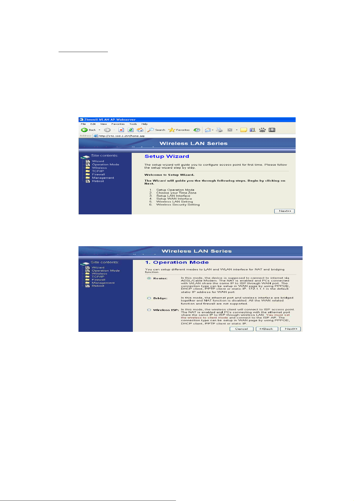
Configure DEV1:
1. Connect the ADSL modem to Ethernet port of device using
Ethernet cable.
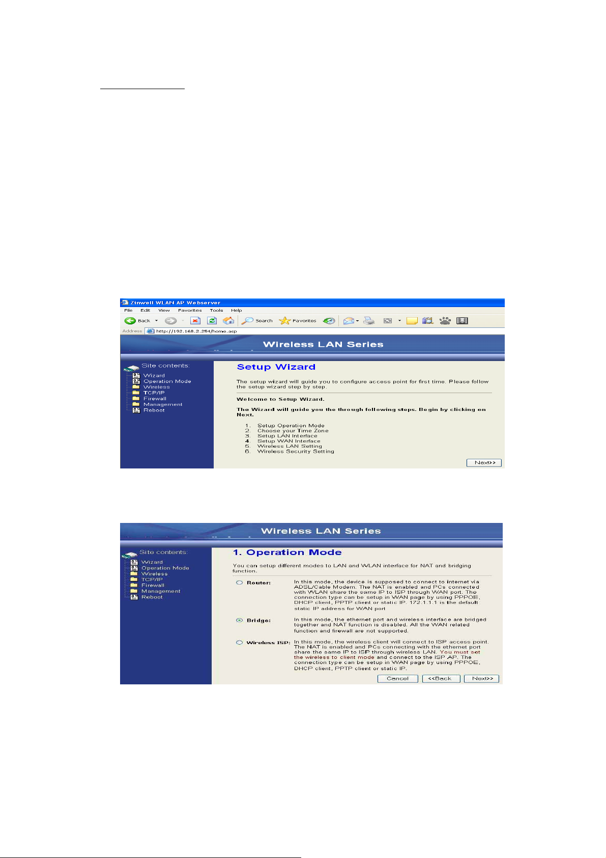
2. Access the web server (http://192.168.2.254) of device from the
wireless station.
3. Use Wizard page to setup deviceˁ
4. Press “Next>>” button then set the “Operation Mode” to “Router”
mode.
12
Page 15
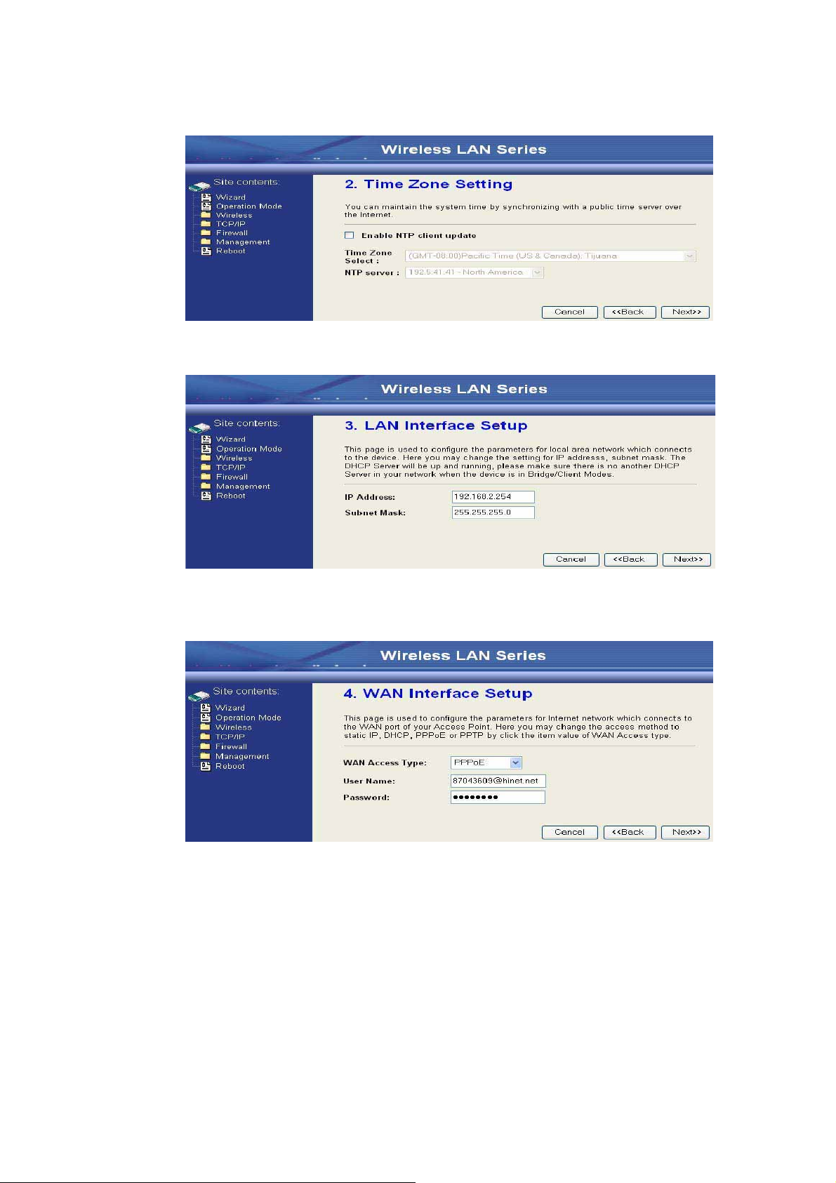
5. Press “Next>>” button then disable “Time Zone” function.
6. Press “Next>>” button then set the IP address of LAN interface.
7. Press “Next>>” button then select the “PPPoE” for “WAN Access
Type” and fill in the “User Name” and “Password” fields.
13
Page 16
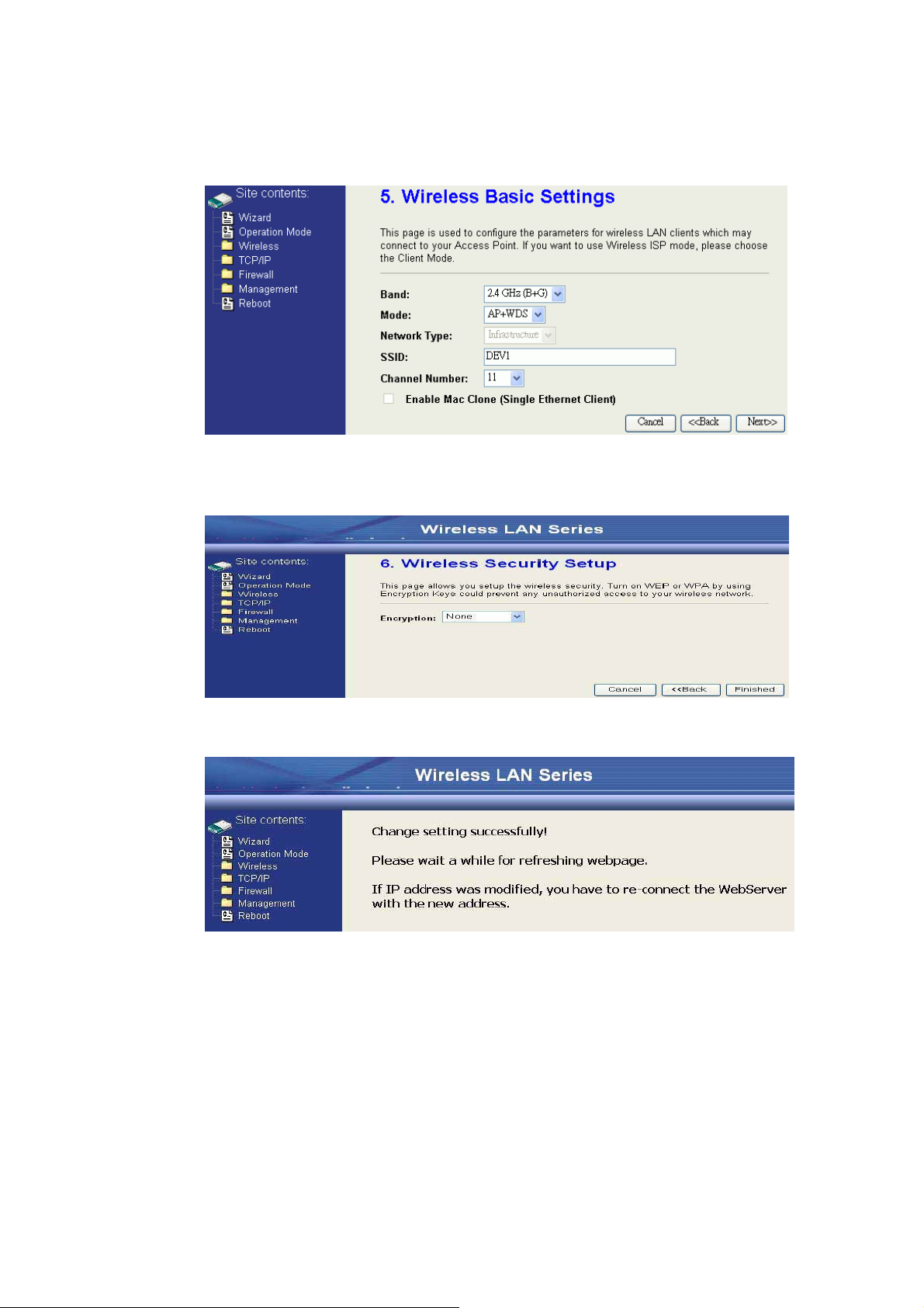
8. Press “Next>>” button then select the “AP+WDS” for “mode” and ʳ
change theʳSSID to “DEV1”.
9. Press “Next>>” button then select “None” for “Encryption” then
press“Finished” button.
10. Wait for refreshing web page.
14
Page 17
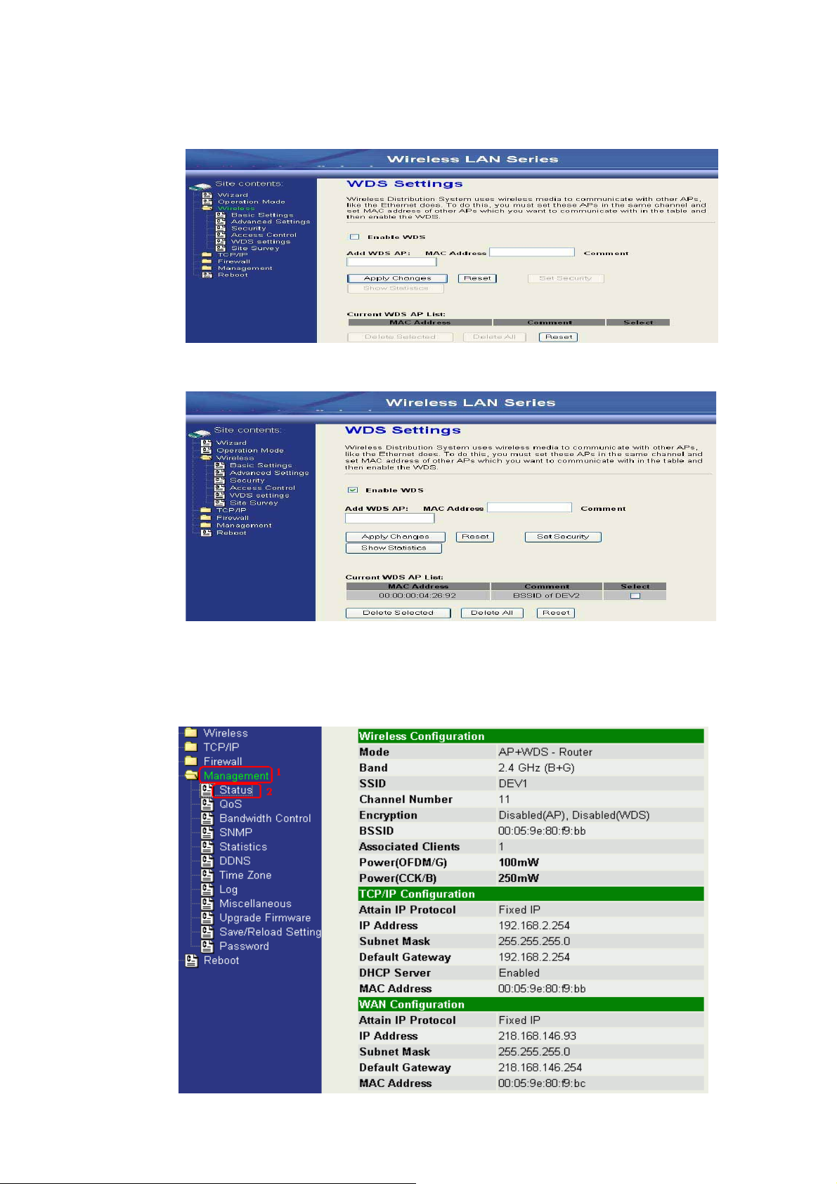
11. Use “WDS Settings” page to configure WDS.
12. Enable WDS function and add the BSSID of DEV2 to “Current WDS
AP List”.
13. Since we access the device by wireless connection, it may
temporarily disconnect when applying the WDS setting. After
re-connecting to the device, use the “Status” page to check the
settings.
15
Page 18

Configure DEV2:
Caution
1. Access the web server (http://192.168.2.254). of device from the
Ethernet port.
If you configure multiple devices in the same PC, since the devices have
the same default IP address but different MAC addresses, it may cause you
not able to access the web server of device. If the situation happens, please
try to clean the ARP table of your PC by DOS command “arp –d” then you
can access the web server of device using the default IP address.
2. Use Wizard page to setup device.
3. Press “Next>>” button then set the “Operation Mode” to “Bridge”
mode.
16
Page 19

4. Press “Next>>” button then disable “Time Zone” function.
5. Press “Next>>” button then set the IP address of LAN interface.
6. Press “Next>>” button then select the “AP+WDS” for “mode” and
change theʳSSID to “DEV2”.
17
Page 20

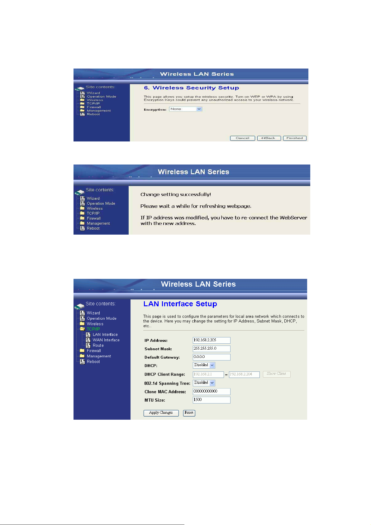
7. Press “Next>>” button then select “None” for “Encryption” then press
“Finished” button.
8. Wait for refreshing web page.
9. Access the web server by new IP address “192.168.2.202” then use
“LAN Interface” page to disable DHCP Server.
18
Page 21

10. Wait for refreshing web page.
11. Use “WDS Settings” page to configure WDS.
12. Enable WDS function and add the BSSID of DEV1 to “Current WDS
AP List”.
19
Page 22

13. Use the “Status” page to check the settings.
20
Page 23

Configure DEV3:
Caution
1. Access the web server (http://192.168.2.254) of device from the
Ethernet port.
If you configure multiple devices in the same PC, since the devices
have the same default IP address but different MAC addresses, it may
cause you not able to access the web server of device. If the situation
happens, please try to clean the ARP table of your PC by DOS
command “arp –d” then you can access the web server of device using
the default IP address.
2. Use “LAN Interface” page to set the IP address of LAN interface and
disable
ʳʳʳDHCP server.
3. Wait for refreshing web page.
21
Page 24

4. Access the web server by new IP address “192.168.2.203” then use
“Basicʳ
Settings” page to change SSID and CHANNEL.
5. Use the “Status” page to check the settings.
22
Page 25

Configure DEV4:
Caution
1. Access the web server (http://192.168.2.254) of device from the
Ethernet port.
If you configure multiple devices in the same PC, since the devices have the
same default IP address but different MAC addresses, it may cause you
unable to access the web server of device. If the situation happens, please
try to clean the ARP table of your PC by DOS command “arp –d” then you
can access the web server of device using the default IP address.
2. Use Wizard page to setup device.
3. Press “Next>>” button then set the “Operation Mode” to “Wireless ISP”
mode.
23
Page 26
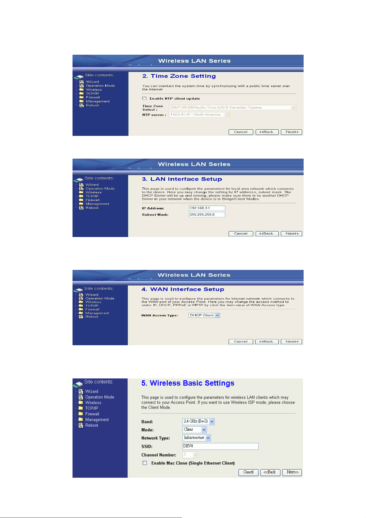
4. Press “Next>>” button then disable “Time Zone” function.
5. Press “Next>>” button then set the IP address of LAN interface.
6. Press “Next>>” button then select the “DHCP Client” for “WAN Access
Type”.
7. Press “Next>>” button then select the “Client” for “mode” and change
theʳSSID to “DEV4”.
24
Page 27
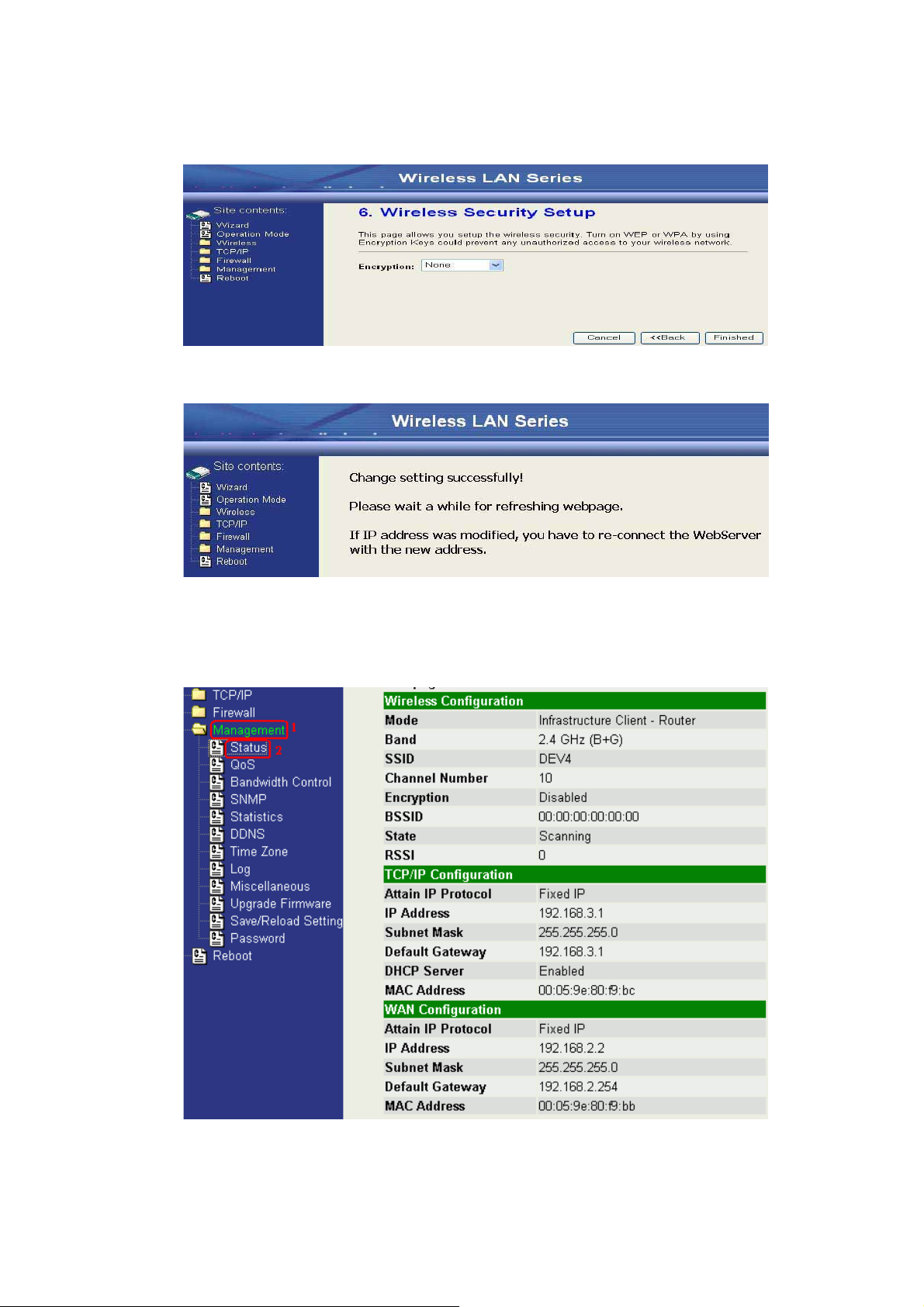
8. Press “Next>>” button then select “None” for “Encryption” then press
“Finished” button.
9. Wait for refreshing web page.
10.Change the IP address of your PC to 192.168.3.x then access the web
server by the new IP address “192.168.3.1” and use “Status” page check
the setting.
25
Page 28

11.If the “State” of “Wireless Configuration” is not “Connected” or you want
to refresh the “RSSI “, please use “Site Survey” page to re-connect a AP.
26
Page 29
Configure DEV5:
Caution
1. Access the web server (http://192.168.2.254) of device from the
Ethernet port.
If you configure multiple devices in the same PC, since the devices have
the same default IP address but different MAC addresses, it may cause you
unable to access the web server of device. If the situation happens, please
try to clean the ARP table of your PC by DOS command “arp –d” then you
can access the web server of device using the default IP address.
2. Use Wizard page to setup device.
3. Press “Next>>” button then set the “Operation Mode” to “Wireless ISP”
mode.
27
Page 30

4. Press “Next>>” button then disable “Time Zone” function.
5. Press “Next>>” button then set the IP address of LAN interface.
6. Press “Next>>” button then select the “Client” for “mode” and change
theʳSSID to “DEV5”.
28
Page 31
7. Press “Next>>” button then select “None” for “Encryption” then pressʳ
“Finished” button.
8. Wait for refreshing web page.
9. Access the web server by the new IP address “192.168.2.205” and useʳ
“LANʳ
Interface” page to disable DHCP Server.
29
Page 32
10.Wait for refreshing webpage
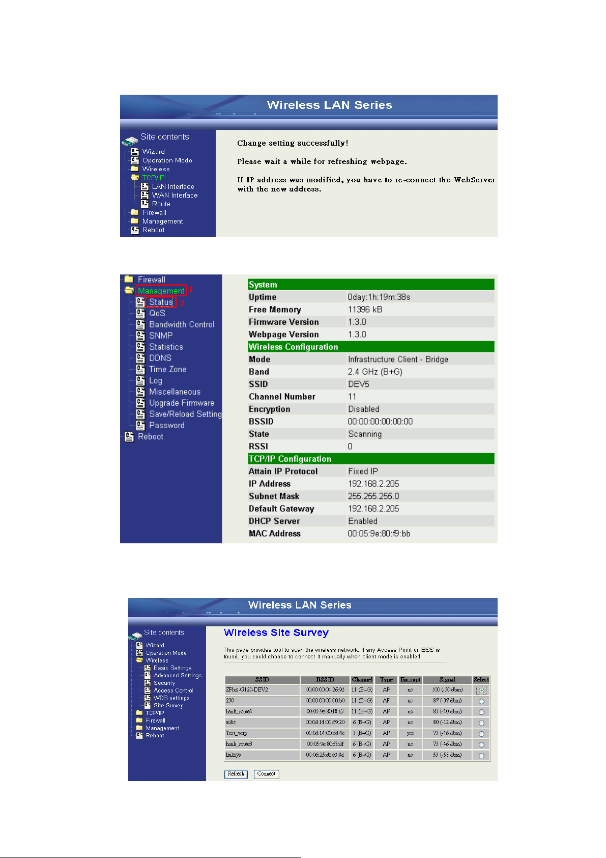
11.Use “State” page to check setting.
12.If the “State” of “Wireless Configuration” is not “Connected” or you want
to refresh the “RSSI “, please use “Site Survey” page to re-connect a AP.
30
Page 33

Basic Settings
1. APʳ
2. Client
3. WDSʳ
4. AP+WDS
Disable Wireless LAN Interface
Disable the wireless interface of device
Band:
The device supports 2.4GHz(B), 2.4GHz(G) and 2.4GHz(B+G) mixed modes.
Mode:
The radio of device supports different modes as following:
The radio of device acts as an Access Point to serves all wireless clients to
join a wireless local network.
Support Infrastructure and Ad-hoc network types to act as aʳwireless
adapter.
Wireless Distribution System, this mode serves as a wireless repeater,
only devices with WDS function supported can connect to it, all the wireless
clients can’t survey and connect the device when the mode is selected.
Support both AP and WDS functions, the wireless clients and devices with
WDS function supported can survey and connect to it.
31
Page 34

Infrastructure:
Ad Hoc:
This type requires the presence of 802.11b/g Access Point. All
communication is done via the Access Point.
Ethernet
AP
AP Client #1 AP Client #2
This type provides a peer-to-peer communication between wireless
stations. All the communication is done from Client to Client without any
Access Point involved. Ad Hoc networking must use the same SSID and
channel for establishing the wireless connection.
PC #1
PC #3
AP Client #3
AP Client #1
AP Client #2
PC #2
In client mode, the device can’t support the Router mode function including
Firewall and WAN settings.
32
Page 35

SSID:
Channel Number
Associated Client
The SSID is a unique identifier that wireless networking devices use to
establish and maintain wireless connectivity. Multiple access point/bridges
on a network or sub-network can use the same SSID. SSIDs are case
sensitive and can contain up to 32 alphanumeric characters. Do not include
spaces in your SSID.
The following table is the available frequencies (in MHz) for the 2.4-GHz
radio:
Channel No. frequency Country Domain
1 2412 Americas, EMEA, Japan, and China
2 2417 Americas, EMEA, Japan, and China
3 2422 Americas, EMEA, Japan, Israel, and China
4 2427 Americas, EMEA, Japan, Israel, and China
5 2432 Americas, EMEA, Japan, Israel, and China
6 2437 Americas, EMEA, Japan, Israel, and China
7 2442 Americas, EMEA, Japan, Israel, and China
8 2447 Americas, EMEA, Japan, Israel, and China
9
2452 Americas, EMEA, Japan, Israel, and China
10 2457 Americas, EMEA, Japan, and China
11 2462 Americas, EMEA, Japan, and China
12 2467 EMEA and Japan only
13 2472 EMEA and Japan only
14 2484 Japan only
When set to “Auto”, the device will find the least-congested channel for use.
Show the information of active wireless client stations that connected to
the device.
33
Page 36

Advanced Settings
NoteΚ
Any unreasonable value change to default setting will reduce the throughput
of the device.
Authe
ntication Type
Fragment Threshold
These settings are only for more technically advanced users who have
sufficient knowledge about wireless LAN. These settings should not be
changed unless you know what effect the changes will have on your device.
The default setting is optimized for the normal operation. For specific
application, setting configuration will required highly attention to reach
optimistic condition.
The device supports two Authentication Types “Open system” and “Shared
Key”. When you select “Share Key”, you need to setup “WEP” key in
“Security” page (See the next section). The default setting is “Auto”. The
wireless client can associate with the device by using one of the two types.
The fragmentation threshold determines the size at which packets are
fragmented (sent as several pieces instead of as one block). Use a low
setting in areas where communication is poor or where there is a great deal
of radio interference. This function will help you to improve the network
performance.
34
Page 37

RTS Threshold
Data Rate
Beacon Interval
Broadcast SSID
Int. Roaming
NoteΚʳ
For implementing the roaming function, the setting MUST comply the
following two items.
All the devices must be in the same subnet network and the
SSID must be the same
.
If you use the 802.1x authentication, you need to have the
userʳprofile in these devices for the ro
aming station.
The RTS threshold determines the packet size at which the radio issues a
request to send (RTS) before sending the packet. A low RTS Threshold
setting can be useful in areas where many client devices are associating
with the device, or in areas where the clients are far apart and can detect
only the device and not each other. You can enter a setting ranging from 0 to
2347 bytes.
The standard IEEE 802.11b/11g supports 1, 2, 5.5, 11 / 6, 9, 12, 18, 24,
36, 48 and 54 Mbps data rates. You can choose the rate that the device
uses for data transmission. The default value is “auto”. The device will use
the highest possible selected transmission rate.
The beacon interval is the amount of time between access point beacons
in mini-seconds. The default beacon interval is 100.
Broadcasting the SSID will let your wireless clients find the device
automatically. If you are building a public Wireless Network, disable this
function can provide better security. Every wireless stations located within
the coverage of the device must connect this device by manually configure
the SSID in your client settings.
This function will let Wireless Stations roam among a network
environment with multiple devices. Wireless Stations are able to switch from
one device to another as they move between the coverage areas. Users can
have more wireless working range. An example as the following figure
You should comply with the following instructions to roam among the
wireless coverage areas.
35
Page 38

Block WLAN Relay (Isolate Client)
Transmit Power
The device supports isolation function. If you are building a public
Wireless Network, enable this function can provide better security. The
device will block packets between wireless clients (relay). All the wireless
clients connected to the device can’t see each other.
The device supports four transmission output power levels 250, 200, 150
andʳ100mW for CCK (802.11b) mode and two transmission output power
levelsʳ100 and 50mW for OFDM (802.11g) mode. User can adjust the power
level to change the coverage of the device. Every wireless stations located
within the coverage of the device also needs to have the high power radio.
Otherwise the wireless stations only can survey the device, but can’t
establish connection with device.
36
Page 39
Configuring Wireless Security
WEP Encryption Setting
This device provides complete wireless security function include WEP,
802.1x, WPA-TKIP, WPA2-AES and WPA2-Mixed in different mode (see the
Security Support Table).
The default security setting of the encryption function is disabled. Choose
your preferred security setting depending on what security function you
need.
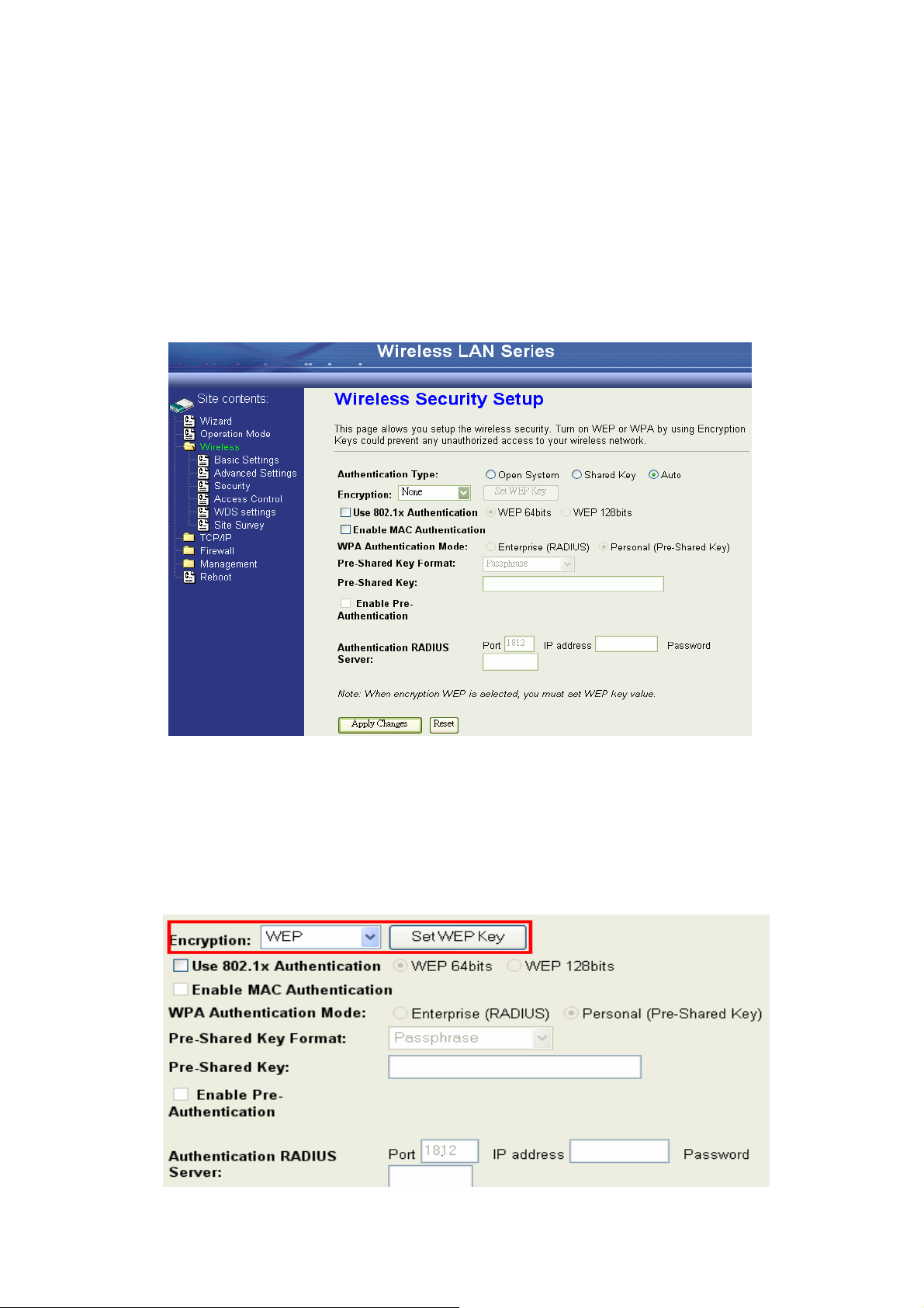
Wired Equivalent Privacy (WEP) is implemented in this device to
prevent unauthorized access to your wireless network. The WEP setting
must be as same as each client in your wireless network. For more secure
data transmission, you can change encryption type to “WEP” and click the
“Set WEP Key” button to open the “Wireless WEP Key setup” page.
37
Page 40

When you decide to use the WEP encryption to secure your WLAN,
WEP Encryption with 802.1x Setting
please refer to the following setting of the WEP encryption:
ϥʳ 64-bit WEP EncryptionΚ64-bit WEP keys are as same as the encryption
method of 40-bit WEP. You can input 10 hexadecimal digits (0~9, a~f
or A~F) or 5 ACSII chars.
ϥʳ 128-bit WEP EncryptionΚ128-bit WEP keys are as same as the
encryption method of 104-bit WEP. You can input 26 hexadecimal
digitsʳ(0~9, a~f or A~F) or 10 ACSII chars.
ϥʳ The Default Tx Key field decides which of the four keys you want to use
in your WLAN environment.
The device supports external RADIUS Server that can secure networks
against unauthorized access. If you use the WEP encryption, you can also
use the RADIUS server to check the admission of the users. By this way
every user must use a valid account before accessing the Wireless LAN and
requires a RADIUS or other authentication server on the network. An
example is shown as following.
38
Page 41
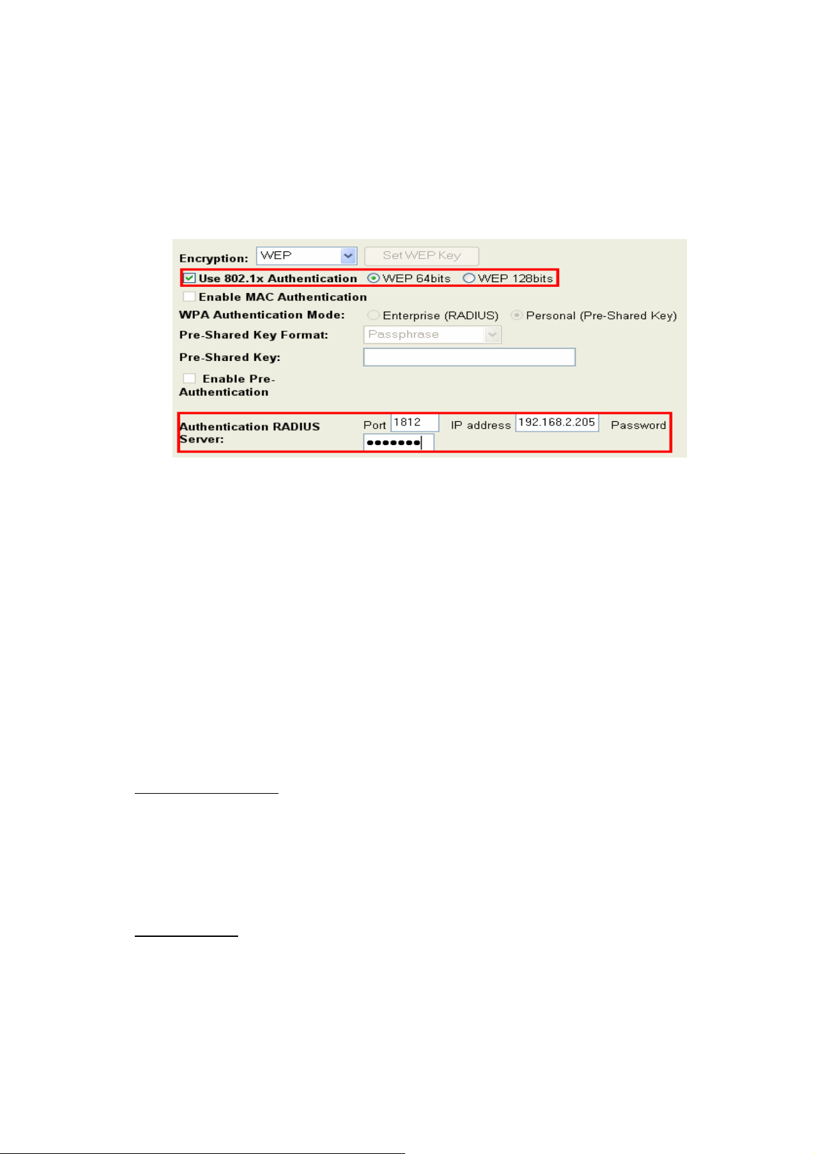
You should choose WEP 64 or 128 bit encryption to fit with your
WPA Encryption Setting
WPA Authentication Mode
Enterprise (RADIUS):
Pre-Share Key:
network environment first. Then add user accounts and the target device
to the RADIUS server. In the device , you need to specify the IP addressΕ
Password
Shared Secret) and Port number of the target RADIUS server.
WPA feature provides a high level of assurance for end-users and
administrators that their data will remain private and access to their
network restricted to authorized users. You can choose the WPA encryption
and select the Authentication Mode.
This device supports two WPA modes. For personal user, you can use the
Pre-shared Key to enhance your security setting. This mode requires only an
access point and client station that supports WPA-PSK. For Enterprise,
authentication is achieved via WPA RADIUS Server. You need a RADIUS or
other authentication server on the network.
When WPA Authentication mode is Enterprise (RADIUS), you have to add
user accounts and the target device to the RADIUS Server. In the device , you
need to specify the IP addressΕPassword (Shared Secret) and Port number
of the target RADIUS server.
This mode requires only an access point and client station that supports
WPA-PSK. The WPA-PSK settings include Key Format, Length and Value.
They must be as same as each wireless client in your wireless network.
When Key format is Passphrase, the key value should have 8~63 ACSII
chars. When Key format is Hex, the key value should have 64 hexadecimal
digits (0~9, a~f or A~F).
39
Page 42

Configuring as WLAN Client Adapter
Step 1.
Step 2.
This device can be configured as a wireless Ethernet adapter. In this
mode, the device can connect to the other wireless stations (Ad-Hoc network
type) or Access Point (Infrastructure network type) and you don’t need to
install any driver.
Quick start to configure
In “Basic Settings” page, change the Mode to “Client” mode.
And key in the SSID of the AP you want to connect then press “Apply
Changes” button to apply the change.
Check the status of connection in “Status” web page
The alternative way to configure as following:
40
Page 43
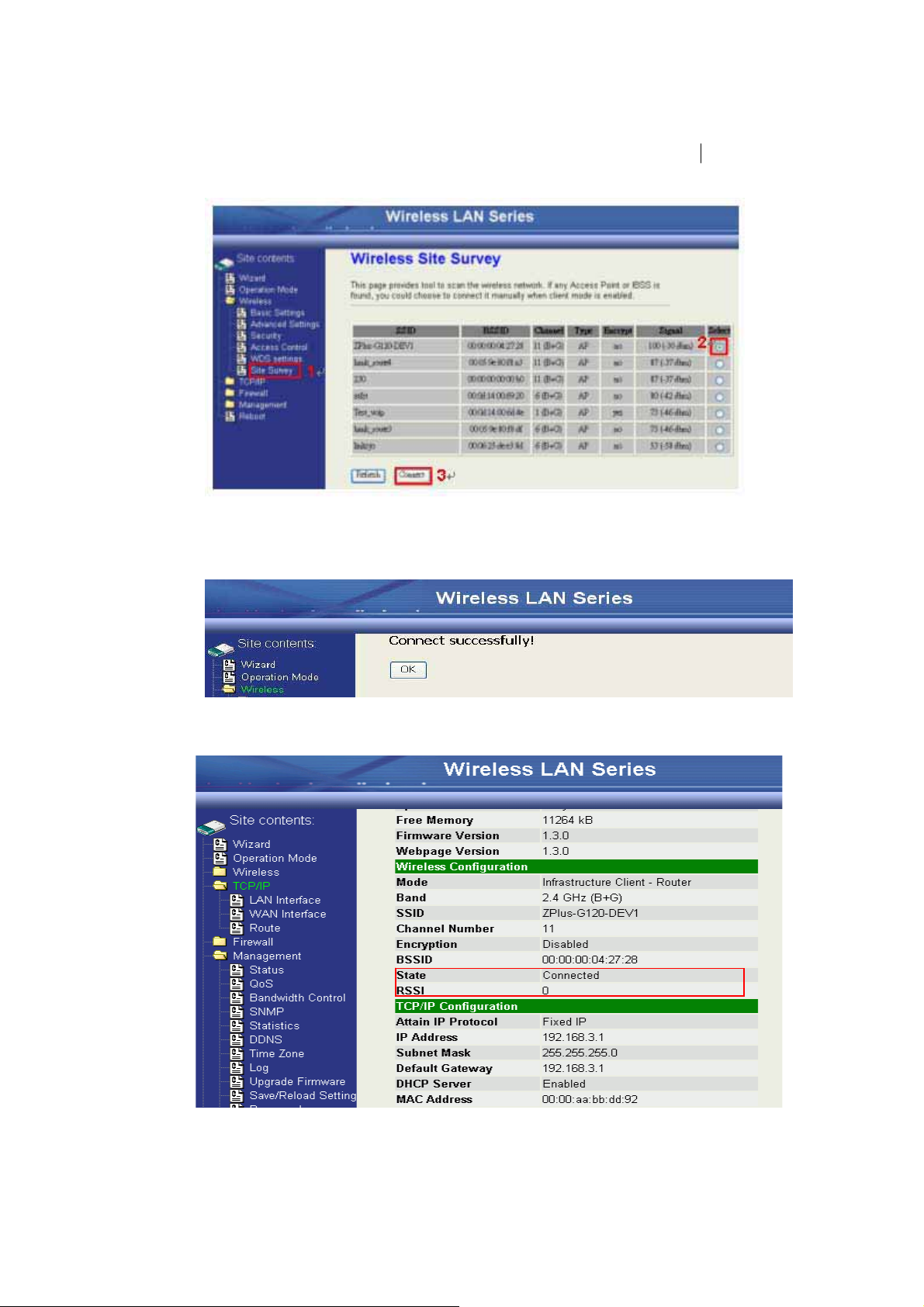
The Alternative way to configure as following:
Step 1
Step 2
Step 3.
. In “Wireless Site Survey” page, select one of the SSIDs you
want to connect and then press “Connect” button to establish the link.
. If the linking is established successfully. It will show the
messageʳ“Connect successfully”. Then press “OK”.
Then you can check the linking information in “Status” page.
41
Page 44

Note Κ
If the available network requires authentication and data encryption, you
need to setup the au
thentication and encryption before step1 and all the
settings must be as same as the Access Point or
Station. About the detail
authentication and data encryption settings, please refer the security
sect
ion.
Authentication Type
Data Encryption
In client mode, the device also supports two Authentication Types “Open
system” and “Shared Key”. Although the default setting is “Auto”, not every
Access Points can support “Auto” mode. If the authentication type on the
Access Point is knew by user, we suggest to set the authentication type as
same as the Access Point.
In client mode, the device supports WEP and WPA Personal/Enterprise
except WPA2 mixed mode data encryption. About the detail data encryption
settings, please refer the security section.
42
Page 45

Configuring Universal Repeater
Note: Under APΕWDS and AP+WDS mode, The Universal Repeater can take
effective.
This device can be configured as a Repeater. In this mode, the device can
extend available wireless range of other AP let user can link the network
that they want, Also the device working as AP and Repeater same time.
Following two ways describe how to make Universal Repeater effective.
1. Enable Universal Repeater Mode and then select a SSID in the Table
that you want. Final click Apply Changes button to take effective. (Click
Refresh button to make table renew)
43
Page 46

2. Enter specific SSID in the Extended SSID field and then click Apply
Changes button to take effective.
44
Page 47

3. Configuring WDS
WDS network topology
Bus topology:
Wireless Distribution System (WDS) uses wireless media to communicate
with the other devices, like the Ethernet does. This function allows one or
more remote LANs connect with the local LAN. To do this, you must set
these devices in the same channel and set MAC address of other devices
you want to communicate with in the WDS AP List and then enable the
WDS.
When you decide to use the WDS to extend your WLAN, please refer the
following instructions for configuration.
ɿ The bridging devices by WDS must use the same radio channel.
ɿ When the WDS function is enabled, all wireless stations can’t connect the
device.
ɿ If your network topology has a loop, you need to enable the 802.1d
Spanning Tree function.
ɿ You don’t need to add all MAC address of devices existed in your network
to WDS AP List. WDS AP List only needs to specify the MAC address of
devices you need to directly connect to.
ɿ The bandwidth of device is limited, to add more bridging devices will split
the more bandwidth to every bridging device.
In this section, we will demonstrate the WDS network topologies and
WDS AP List configuration. You can setup the four kinds of network
topologies: bus, star, ring and mesh.
In this case, there are five devices with WDS enabled: WDS1, WDS2, WDS3,
WDS4 and WDS5.
45
Page 48
Device Entries of WDS AP List
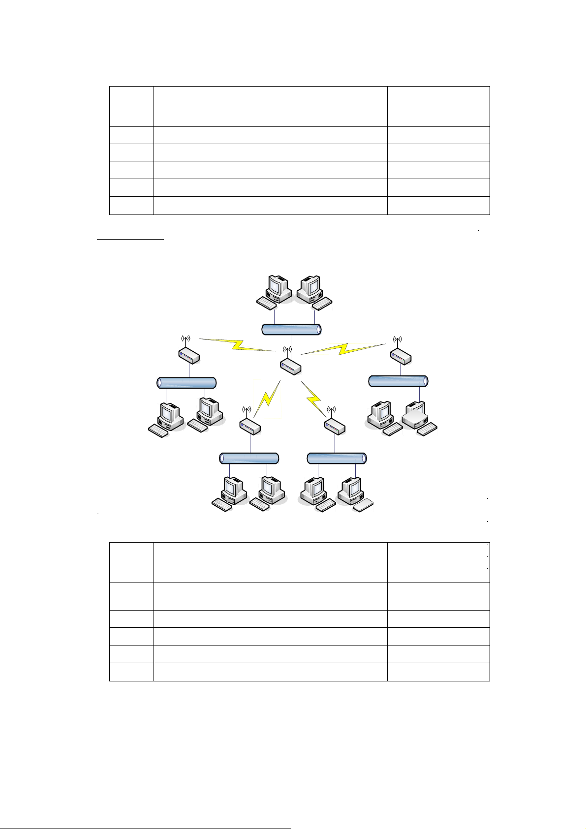
Star topology
Spanning Tree
Protocol Required
WDS1 The MAC Address of WDS2 No
WDS2 The MAC Addresses of WDS1 and WDS3 No
WDS3 The MAC Addresses of WDS2 and WDS4 No
WDS4
The MAC Addresses of WDS3 and WDS5 No
WDS5 The MAC Address of WDS4
No
Device Entries of WDS AP List
WDS1
WDS2
WDS3
WDS4
The MAC Address of WDS2, WDS3, WDS4
and WDS5
The MAC Address of WDS1
The MAC Address of WDS1
The MAC Address of WDS1
WDS5 The MAC Address of WDS1
46
Spanning Tree
Protocol Required
No
No
No
No
No
Page 49

Ring topology:
Device Entries of WDS AP List
WDS1
WDS2
WDS3
WDS4
The MAC Address of WDS2, WDS5
The MAC Address of WDS1, WDS3
The MAC Address of WDS2, WDS4
The MAC Address of WDS3, WDS5
WDS5 The MAC Address of WDS4, WDS1
Spanning Tree
Protocol Required
Yes
Yes
Yes
Yes
Yes
47
Page 50
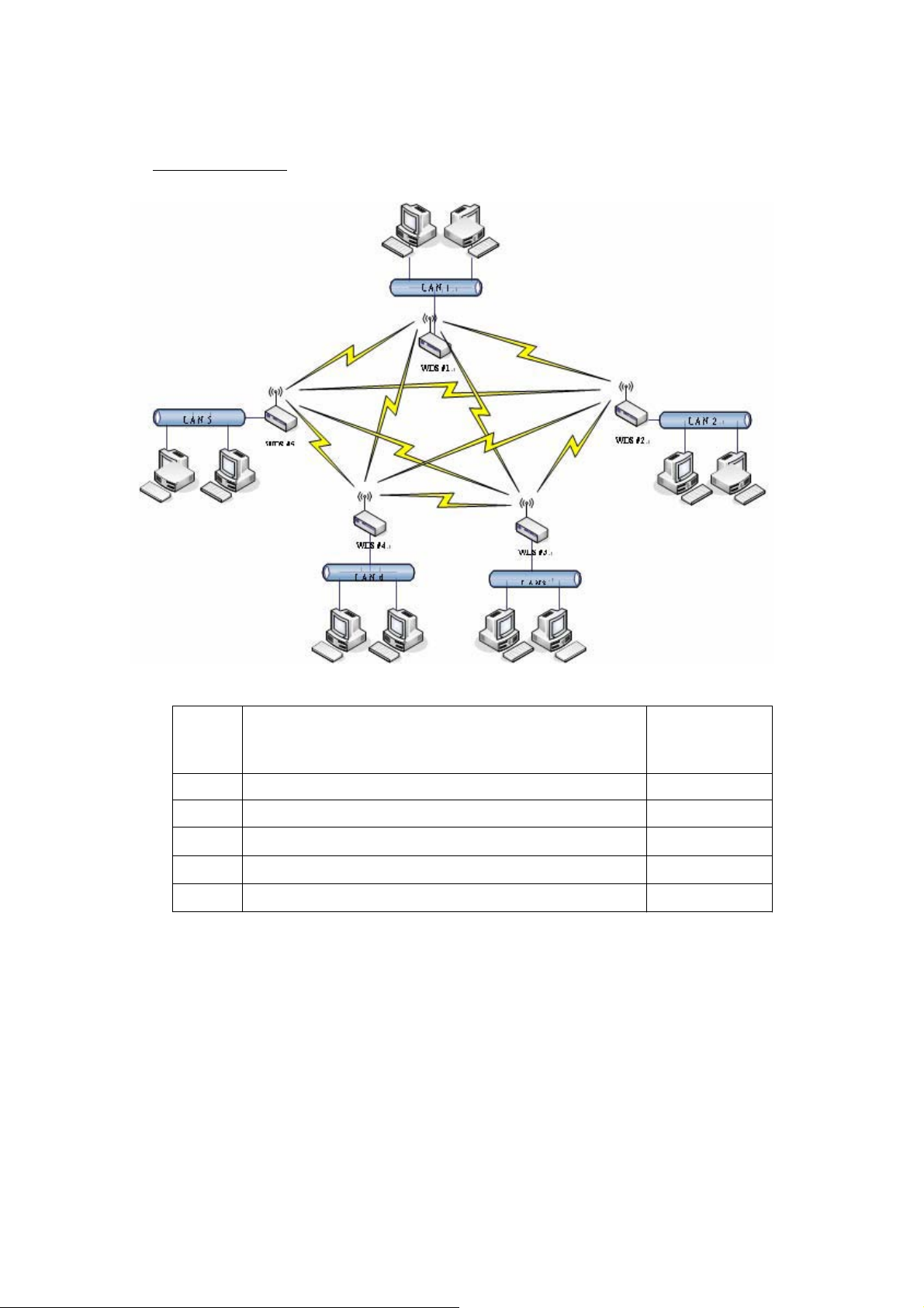
Mesh topologyΚ
Device Entries of WDS AP List
WDS1
WDS2
WDS3
WDS4
WDS5
The MAC Address of WDS2, WDS3, WDS4, WDS5
The MAC Address of WDS˄, WDS3, WDS4, WDS5
The MAC Address of WDS˄, WDS2, WDS4, WDS5
The MAC Address of WDS˄, WDS2, WDS3, WDS5
The MAC Address of WDS˄, WDS2, WDSˆ, WDS4
Spanning Tree
Protocol
Required
Yes
Yes
Yes
Yes
Yes
48
Page 51

WDS Application
Wireless Repeater
Wireless Repeater can be used to increase the coverage area of another
device (Parent AP). Between the Parent AP and the Wireless Repeater,
wireless stations can move among the coverage areas of both devices.
When you decide to use the WDS as a Repeater, please refer the following
instructions for configuration.
ɿ In AP mode, enable the WDS function
ɿ You must set these connected devices with the same radio channel andʳ
SSID.
ɿ Choose “WDS+AP” mode.
ɿ Using the bus or star network topology.
Description Entries of WDS AP List
Access Point The MAC Address of Repeater Yes
Repeater
The MAC Address of Access Point Yes
49
Spanning Tree
Protocol Requires
Page 52

Wireless Bridge
Wireless Bridge can establish a wireless connection between two or more
Wired LANs. When you decide to use the WDS as a Wireless Bridge, please
refer the following instructions for configuration.
ɿ In AP mode, enable the WDS function.
ɿ You must set these connected devices with the same radio channel, but
you may use different SSID.
ɿ Choose “WDS” mode for only wireless backbone extension purpose.
ɿ You can use any network topology, please refer the WDS topology section.
50
 Loading...