

Page 1
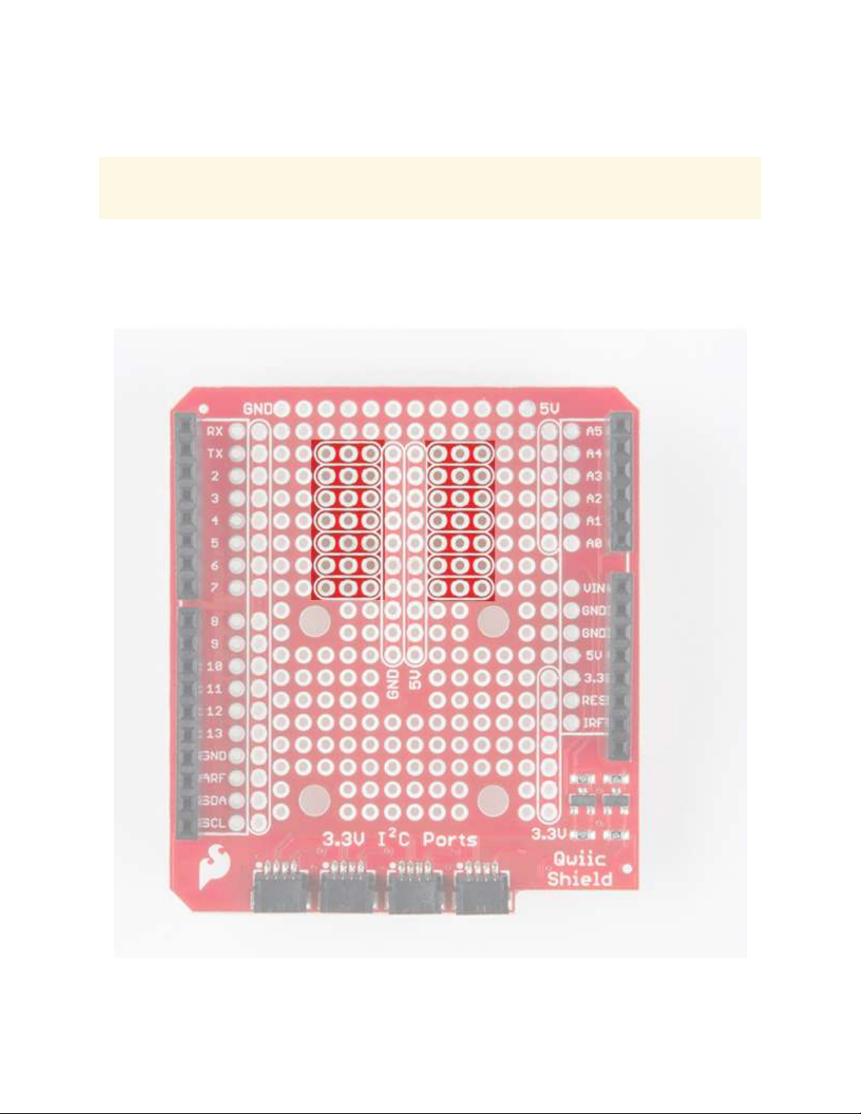
Qwiic Shield for Arduino
Note: The shield includes R3 Arduino headers, but they are not pre-soldered onto the board, so
some assembly will be required when putting the shield together. The image below shows the shield
after the header has been soldered to the PCB to.
The Qwiic Shields have 4x Qwiic connect ports, all on the same I2C bus. Logic level converters are
included for the Qwiic connect port’s SDA and SCL lines so you do not have to worry about using
the Qwiic system with 5V (or 3.3V) devices.
In addition to this, a large prototyping area is included. As shown in the image below, the Qwiic
shield for Arduino has a few neat features such as a few 3-by-1 rails to help with prototyping.
Page 2
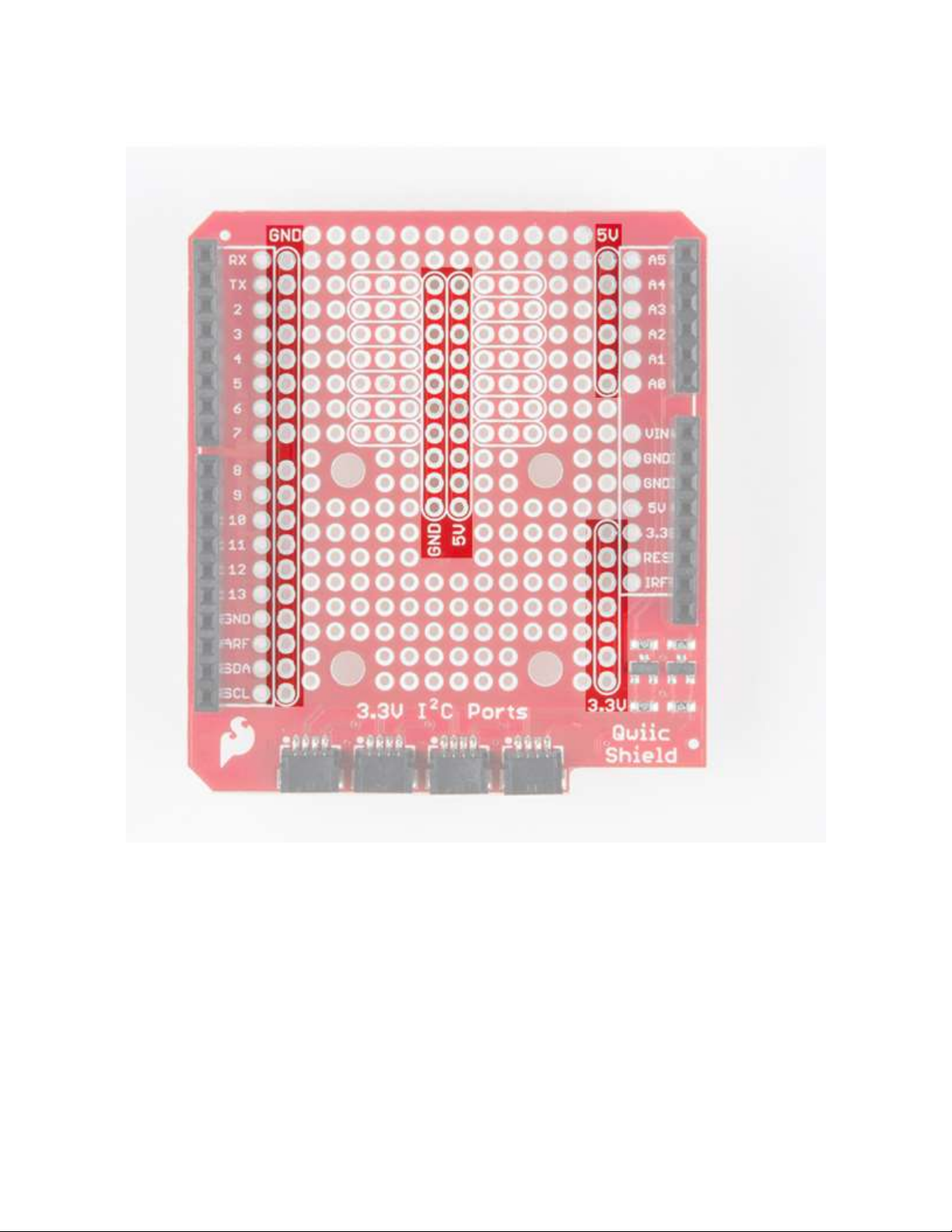
There are also buses for ground, 5V and 3.3V on the shield for Arduino outlined below.
The headers also allow for every pin on the microcontroller of your choice to still be accessed
through the female headers.
Page 3
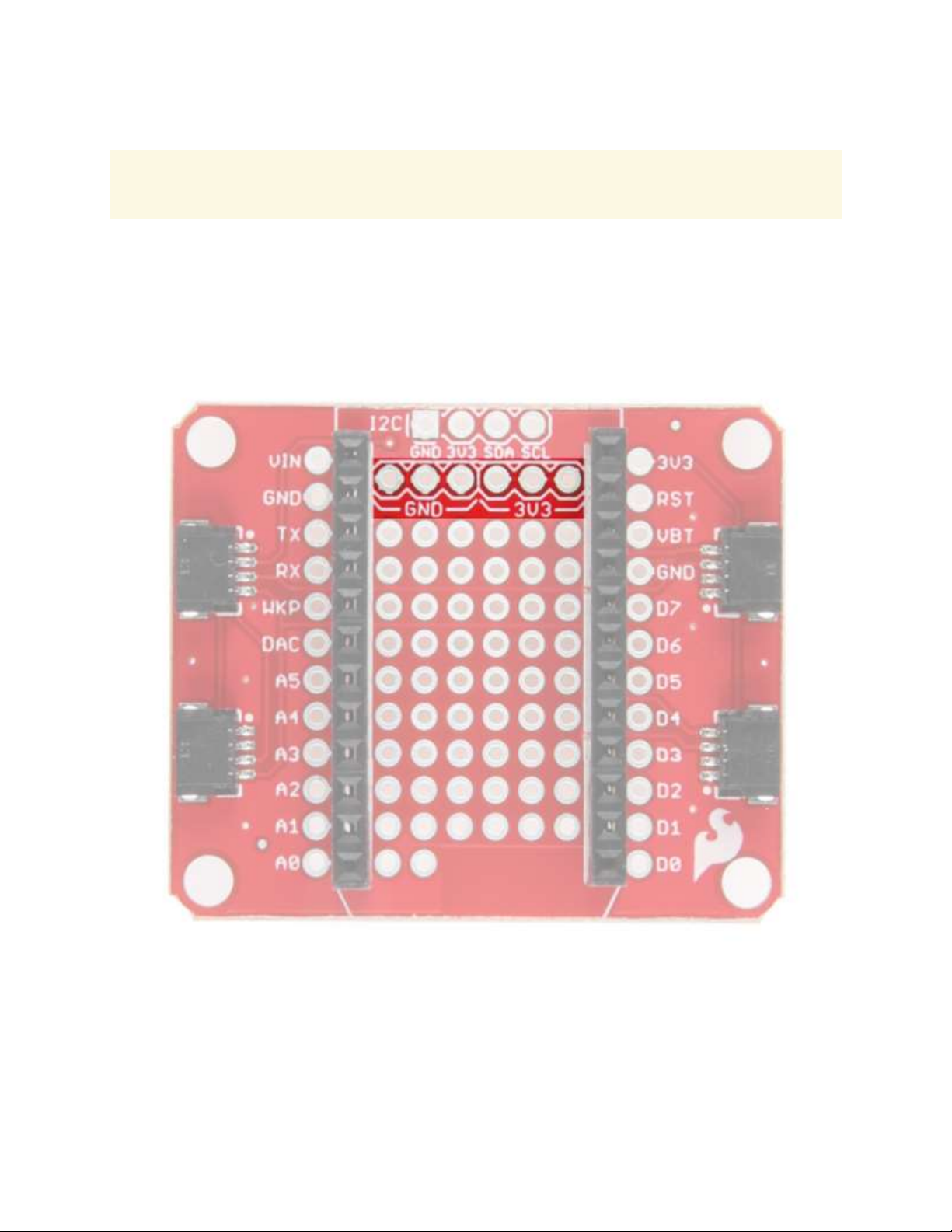
Qwiic Shield for Photon
Note: The shield includes headers, but they are not pre-soldered onto the board, so some assembly
will be required when putting the shield together. The image below shows the shield after the header
has been soldered to the PCB to.
The Qwiic shield for the Particle Photon also includes 4x Qwiic connect ports, a prototyping area,
and buses for 3.3V and ground. However, they are much smaller. The Photon is a 3.3V system and
assumes that you are using 3.3V devices so logic level conversion is not included in the design. If
you are using a 5V based I2C device, be sure to grab a bi-directional logic level converter.
Page 4
Hardware Assembly
To get started with your Qwiic shield, all you’ll need to do is solder on headers. For a detailed
description of how to do this with Arduino shields, simply check out our Arduino shield tutorial. It’ll
get you started with attaching those headers to your shield properly. These tips are also useful when
installing the headers for the Qwiic shield for Photon.
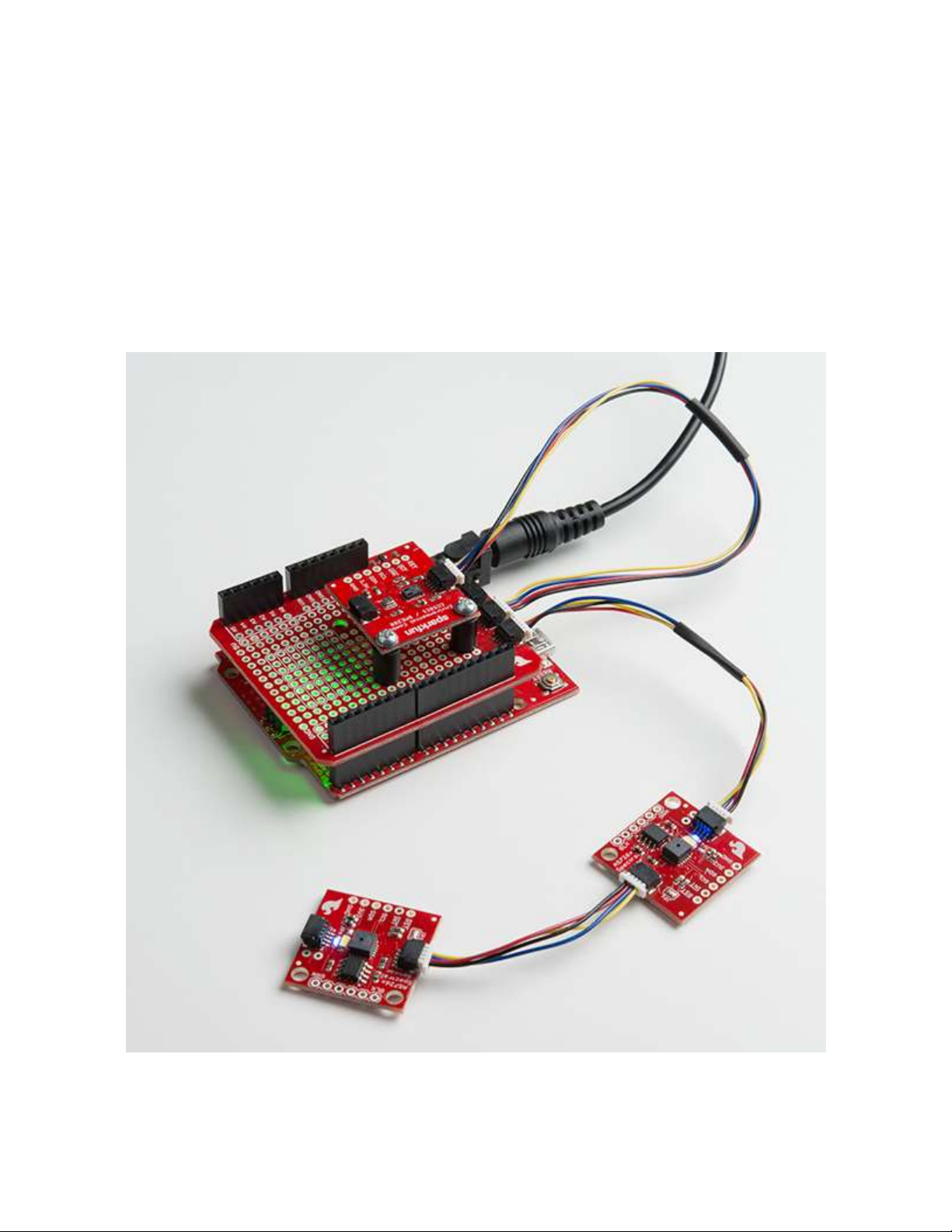
Once you’ve attached headers to your Qwiic shield, you’re ready to plug it into your Qwiic enabled
board of choice. Below is an example of a few Qwiic sensors daisy chained to the Qwiic shield for
Arduino. If you need to mount a Qwiic sensor, just grab a few standoffs and screws. Plug in any
Qwiic enabled board and get going!
Page 5
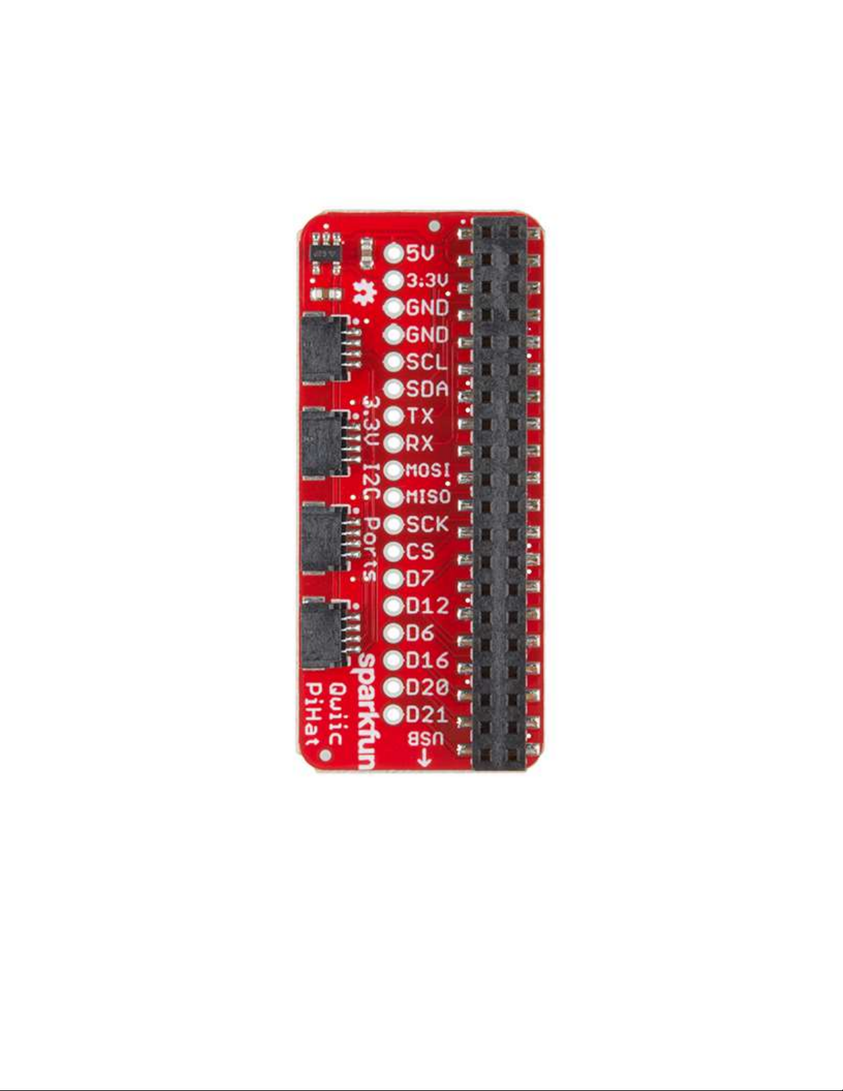
Qwiic HAT for Raspberry Pi
The Qwiic HAT has 4 Qwiic connect ports, all on the same I2C bus. In addition to this, some of the
pins on the Raspberry Pi are broken out for the user.
Page 6
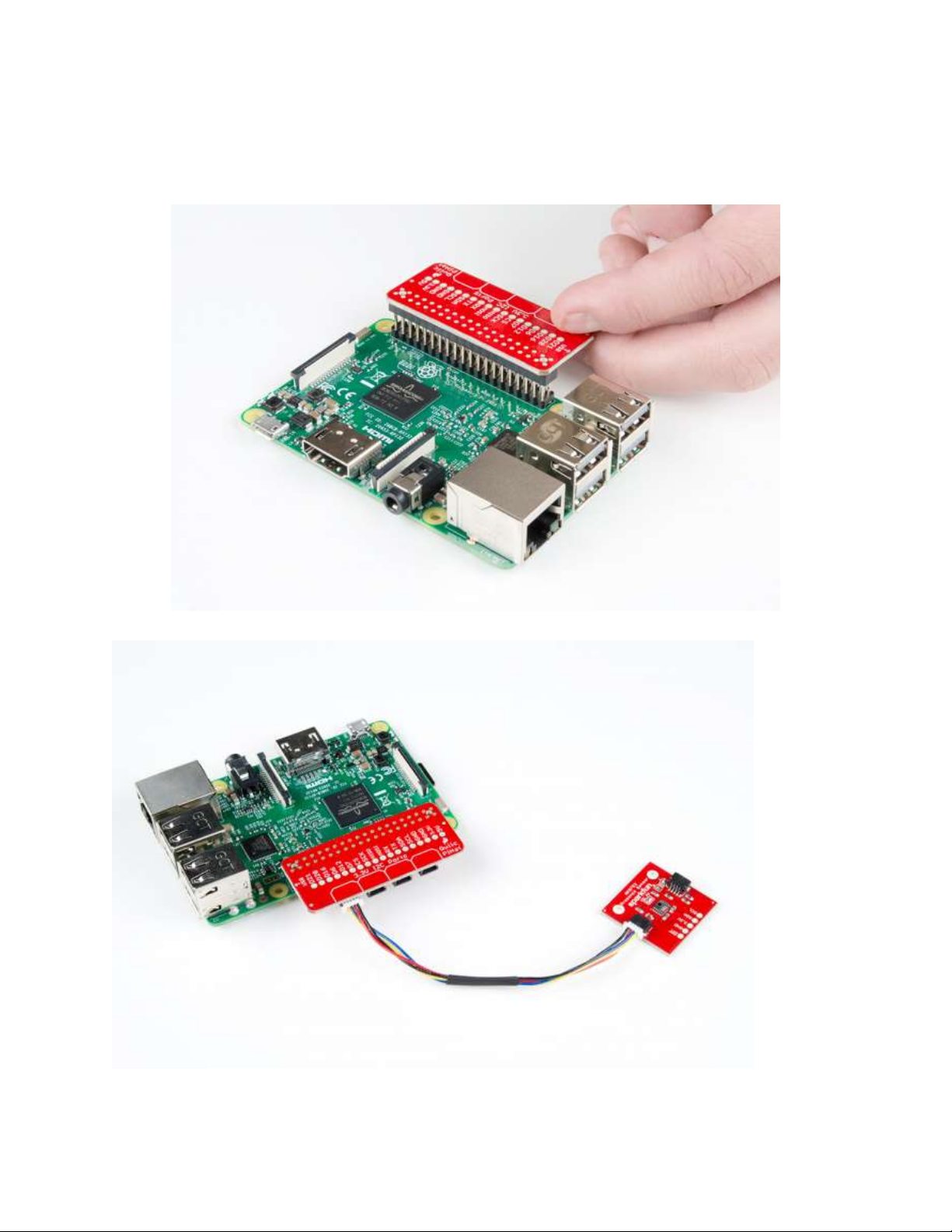
Hardware Assembly
To get started with your Qwiic HAT, simply plug it into the headers on the Raspberry Pi, make sure
that the “USB” arrow on the HAT is pointing towards the USB on the Raspberry Pi.
Once the HAT is plugged in, you can start plugging in any Qwiic enabled sensors you might have.
Page 7

I2C on Raspberry Pi - OS and Library Install
If you’re starting from scratch, with a blank microSD card, you’ll want to install Raspbian. If you’ve
already got a working Raspbian system, skip ahead to step 3.
1. Download the NOOBS image. As of this writing, it’s at version 2.4.4.
2. Follow the official installation instructions.
3. Follow the Wiring Pi Instructions to get git, update and upgrade your Rasbpian packages,
then install WiringPi.
Be patient – each of these steps takes a while.
Once you’ve got wiringPi installed, run the gpio commands shown below.
COPY CODE>gpio -v
>gpio readall
It should respond with some information about the wiringPi version and the Pi that its running on,
then draw a table illustrating the configuration for the pins in the 40-pin connector.
Configuration
Like the SPI peripheral, I2C is not turned on by default. Again, we can use raspi-config to enable it.
1. Run sudo raspi-config.
2. Use the down arrow to select 5 Interfacing Options
3. Arrow down to P5 I2C.
4. Select yes when it asks you to enable I2C
5. Select OK and then Finish
Once you return to terminal, enter this command
COPY CODE>ls /dev/*i2c*
The Pi should respond with
COPY CODE/dev/i2c-1
Which represents the user-mode I2C interface.
Page 8

Utilities
There is a set of command-line utility programs that can help get an I2C interface working. You can
get them with the apt package manager.
COPY CODEsudo apt-get install -y i2c-tools
In particular, the i2cdetect program will probe all the addresses on a bus, and report whether any
devices are present. Call i2cdetect -y 1 to probe the first I2C bus, which is what the Qwiic HAT is
connected to.
COPY CODEpi@raspberrypi:~/$ i2cdetect -y 1
0 1 2 3 4 5 6 7 8 9 a b c d e f
00: -- -- -- -- -- -- -- -- -- -- -- -- -10: -- -- -- -- -- -- -- -- -- -- -- -- -- -- -- -20: -- -- -- -- -- -- -- -- -- -- -- -- -- -- -- -30: -- -- -- -- -- -- -- -- -- -- -- -- -- -- -- -40: -- -- -- -- -- -- -- -- -- -- -- -- -- -- -- -50: -- -- -- -- -- -- -- -- -- -- -- -- -- -- -- -60: 60 -- -- -- -- -- -- -- -- -- -- -- -- -- -- -70: -- -- -- -- -- -- -- --
This map indicates that there is a peripheral at address 0x60. We can read and write its registers
using the i2cget , i2cset and i2cdump commands.
Page 9
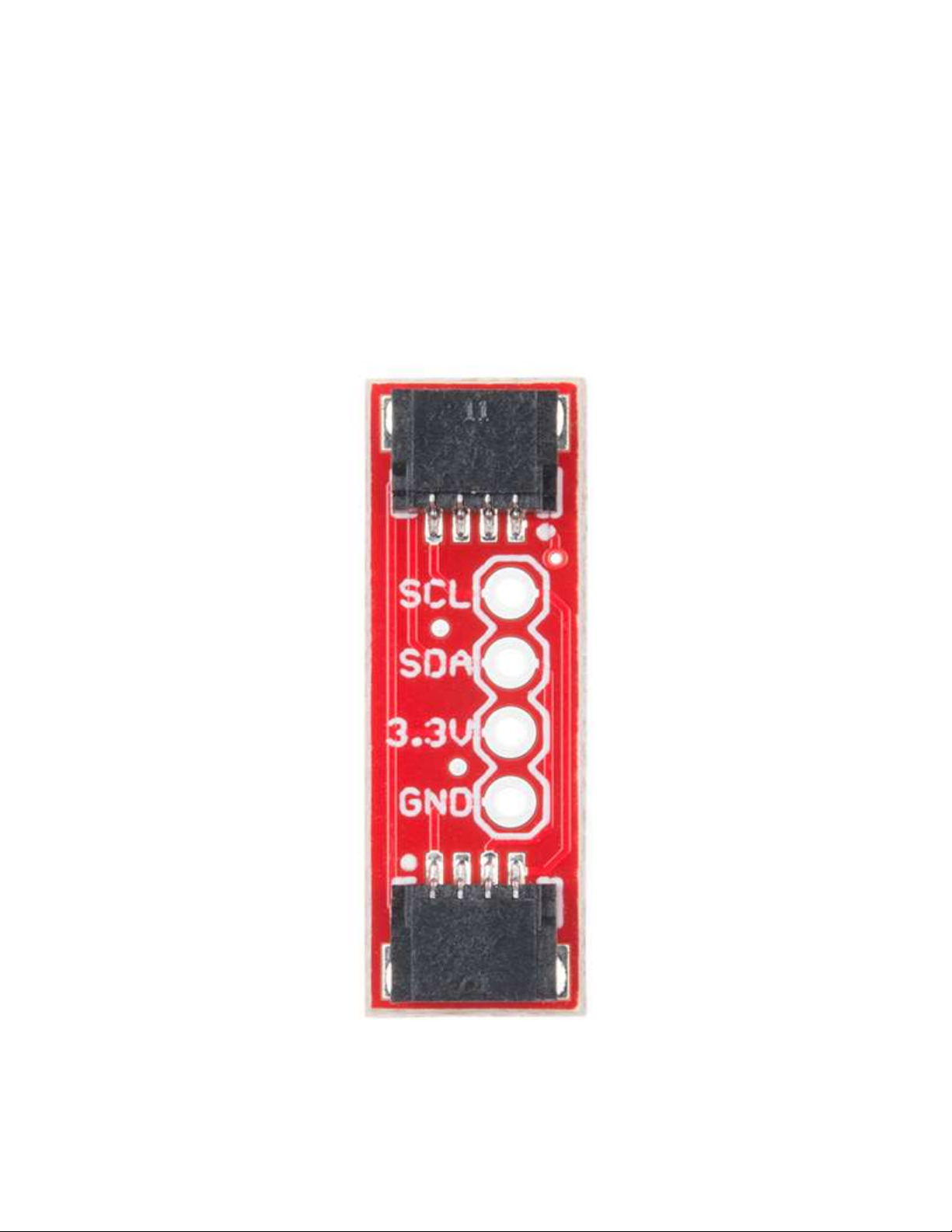
Quiic Adapter
There are a few things you should know about the Qwiic system before you go plugging in I2C
devices willy nilly. The first thing to be aware of is that all Qwiic devices run on 3.3V. So if you have
a 5V device and you are not using a stackable breakout board with a logic level converter (such as
the Qwiic Shield for Arduino), you’ll need to grab a logic level converter to boost your signals up to
5V. Also, be aware that all Qwiic devices have pull-up resistors on the I2C lines. So if your device
does not have it, you’ll need to add those in or use the ones on your microcontroller.
The Qwiic adapter is populated with two 4-pin 1mm JST connectors to quickly connect your I2C
devices together. Four plated through holes are broken out for SCL, SDA, 3.3V, and GND. These
pins can be used to convert an old I2C enabled device into a Qwiic enabled board.
Page 10
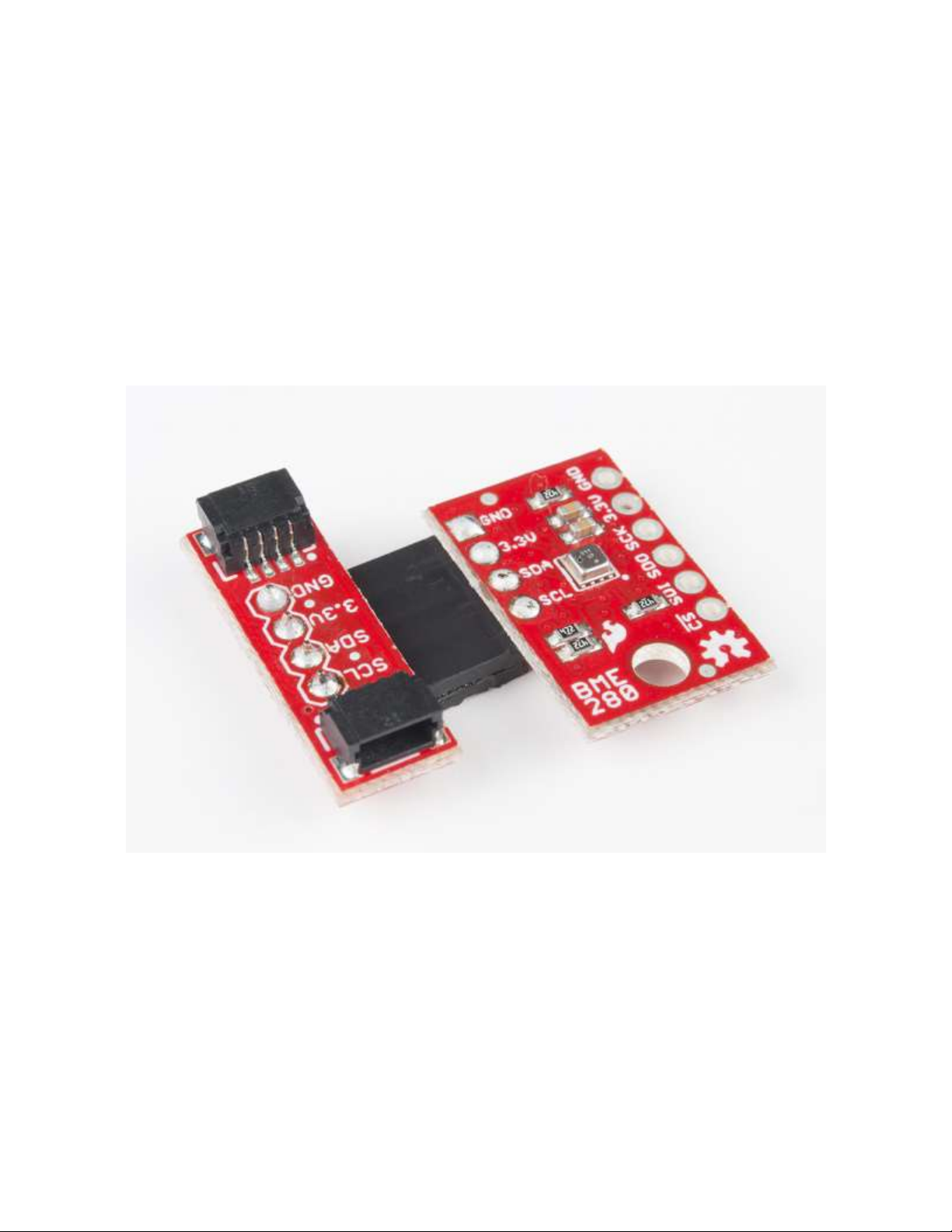
Hardware Assembly
There are several different ways to connect your I2C device to the Qwiic adapter. The simplest and
probably cleanest method would be to use headers. This also allows the adapter to be reattached to
a different I2C device in the future. I’ve found that I enjoy the look of the 90 degree male headers on
the Qwiic Adapter, combined with a 90-degree bend in the legs on the female headers I2C device.
However, you can really use any combination you’d like depending on how you want the adapter to
be oriented relative to your I2C enabled board.
Using pliers, snap off a row of 4 pins from the right angle male header. Using diagonal cutters, you
will need to sacrifice one socket in order cut off a row of 4 pins from the female header. Carefully
bend the female header’s pins using the pliers to make a right angle with the I2C device. Solder the
male headers to the Qwiic adapter and the female headers to the I2C device as shown in the image
below.
Once you’ve got headers soldered onto each of your boards, simply plug your adapter into your I2C
enabled device. Using a Qwiic cable, plug your Qwiic adapter into a stackable Qwiic board of your
choice. Assuming that there is example code loaded on your development board, you can now start
reading data from your I2C enabled device!
 Loading...