

Page 1
GND
VCC
OUT
DS GUIDE
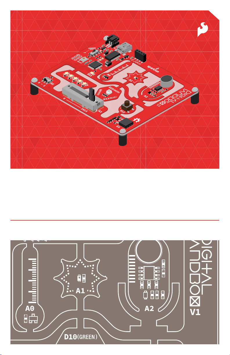
Your guide to the SparkFun Digital Sandbox
Version 1.0
Page 2

Index
Welcome to the Digital Sandbox!
When partnered with the Digital Sandbox, this guide helps to introduce the fundamental concepts
of programming and electronics. Using ArduBlock – a simple, graphical version of the popular
Arduino programming language – you will program 13 experiments that progressively explore
subjects like digital inputs, analog outputs, serial communication and more. The experiments are
project-based, and are built to inspire inventions such as reaction-testing games, automatic
night lights, adjustable volume meters and more.
2 The Anatomy of the Digital Sandbox
4 Digital Sandbox Baseplate Setup
5 Setting up Arduino and ArduBlock
7 Experiment 0: Setup, Loop, and Blink
11 Experiment 1: Exploring Blink
15 Experiment 2: Multi-Blink
19 Experiment 3: Dimming (the Hard Way)
23 Experiment 4: Dimming (the Easy Way)
27 Experiment 5: Color Mixing
31 Experiment 6: Number Storage with Variables
35 Experiment 7: If This, Then That
39 Experiment 8: The Reaction Tester
43 Experiment 9: Serial Calculator
47 Experiment 10: Do the Analog Slide
51 Experiment 11: Automatic Night Light
55 Experiment 12: Thermal Alert!
59 Experiment 13: Sound Detecting
Bonus add-on experiments (parts not included):
63 Experiment 14: Opto-Theremin
69 Experiment 15: Serial Motoring
75 Experiment 16: Servo Sweeper
Page 1
Page 3
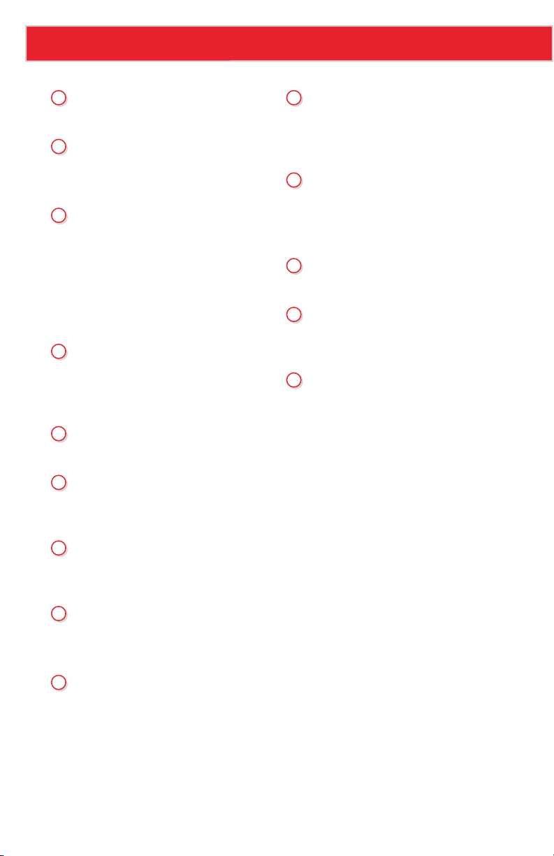
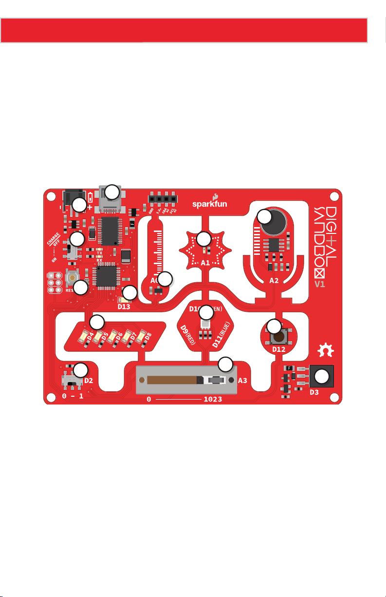
The Anatomy of the Digital Sandbox
1
USB Mini-B Connector
Used to connect to a computer
2
JST Right-Angle
Connector
Used to supply power to the board
3
Slide Switch for
Charging
Used to charge a lithium polymer battery
that is plugged into the two-pin JST
connector, while the Digital Sandbox
is connected to a computer and the slide
switch is in the "ON" position
4
Reset Button
This is a way to manually reset your
Digital Sandbox, which will restart your
code from the beginning.
5
Slide Switch (Pin D2)
On or off slide switch.
6
LEDs (Pins D4-D8)
Use one or all of the LEDs (light-emitting
diodes) to light up your project!
10
RGB LED (Pins D9-D11)
RGB (red-green-blue) LEDs have three
different color-emitting diodes that can be
combined to create many colors.
11
Slide Potentiometer
(Pin A3)
Change the values by sliding it back
and forth.
12
Microphone (Pin A2)
Measures how loud something is
13
Push Button (Pin D12)
A button is a digital input. It can be
either “on” or “off.”
14
Add-on Header (Pin D3)
Three-pin header for add-ons. Example
add-ons are servos, motors and buzzers.
7
LED (Pin 13)
Incorporate this into your sketch to show
whether your program is running properly.
8
Temperature Sensor
(Pin A0)
Measures ambient temperature
9
Light Sensor (Pin A1)
Measures the amount of light hitting
the sensor
Page 2
Page 4
The Anatomy of the Digital Sandbox
1
2
12
3
9
8
4
7
10
6
5
11
13
14
GND
VCC
OUT
Page 3
Page 5
Digital Sandbox Baseplate Setup
GND
VCC
OUT
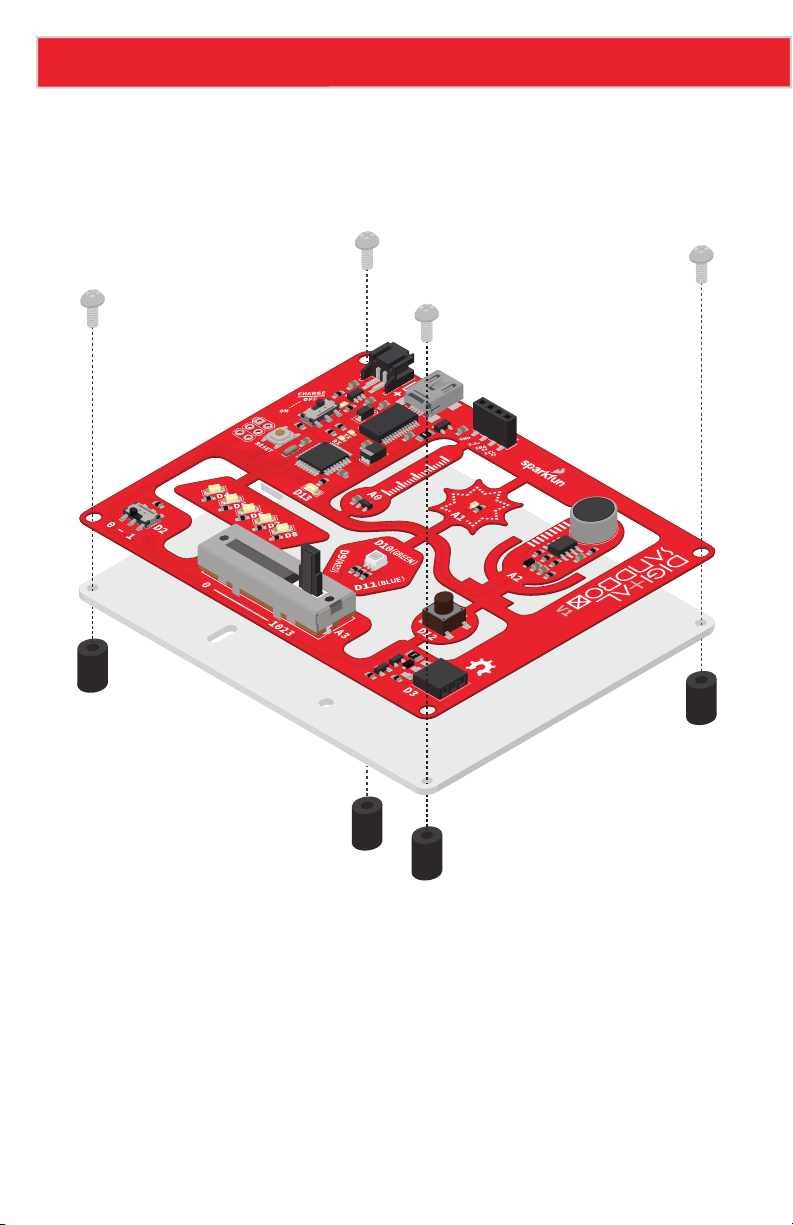
Secure the Digital Sandbox board to the baseplate
The Digital Sandbox board can be attached with the included Phillips-head screws for easy
removal later.
Page 4
Page 6
Setting up Arduino and ArduBlock
Download the Arduino/ArduBlock Combo
Arduino and ArduBlock are available for all popular operating systems. To download Arduino
and ArduBlock, please go to:
www.sparkfun.com/digitalsandbox
Make sure you grab the version that matches your operating system.
The Arduino software comes packaged in an archived .ZIP format. Once you’ve downloaded
the ZIP file, you’ll need to extract it.
Mac users: Move the Arduino application into the Applications folder. Move the Digital
Sandbox Examples folder to your preferred location.
Windows users: Move the Arduino folder to your preferred location.
Install Drivers
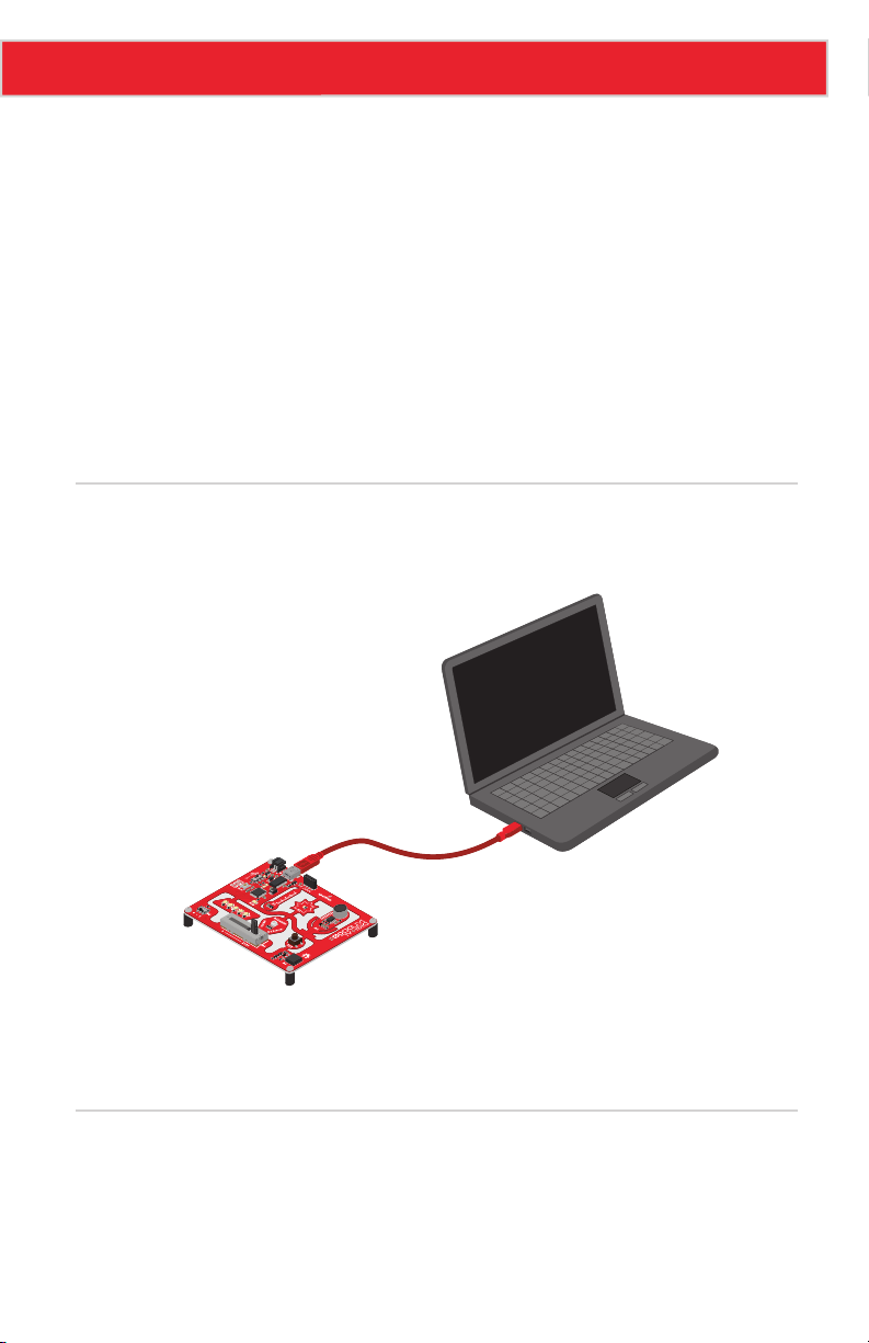
Once you have downloaded and extracted the Arduino software, connect the Digital Sandbox
to your computer.
GND
VCC
OUT
Once the board is connected, you will need to install drivers. For instructions specific to your
operating system, please go to:
www.sparkfun.com/ftdi
Open Arduino and ArduBlock
ArduBlock is an add-on that exists inside the Arduino software. To open it, first open the Arduino
IDE. Windows users should run Arduino.exe; Mac users can run the Arduino application.
Page 5
Page 7
Setting up Arduino and ArduBlock
Serial Port
sketch_01
ArduBlock
/dev/tty.usbserial-AM01VG5K
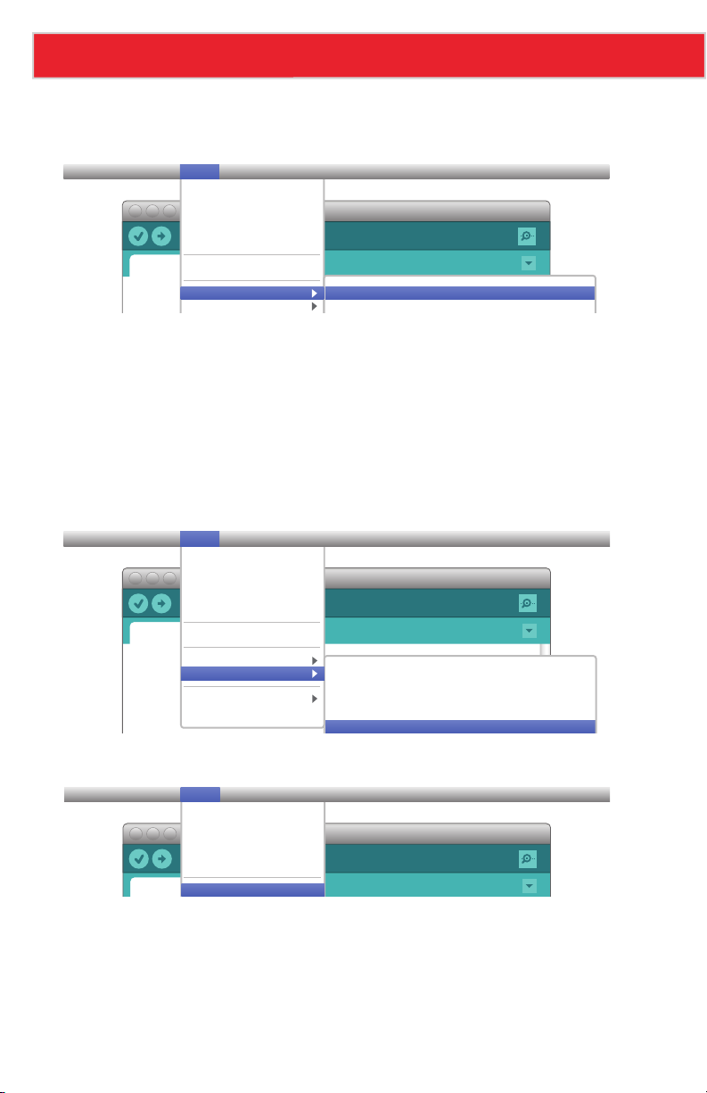
Let’s do some preparation before opening ArduBlock. First, go to the Tools menu, hover over
Board and select Digital Sandbox.
File Edit Sketch Tools Help
sketch_01
Auto Format
Archive Sketch
Fix Encoding &
Reload
Serial Monitor
ArduBlock
Board
Digital Sandbox
Arduino Duemilanove w/ ATmega328]
Next, go back to the Tools menu, hover over Serial Port and select the serial port number
that matches your Sandbox board.
Window users: This is likely to be COM3 or higher (COM1 and COM2 are usually reserved
for hardware serial ports). To find out, you can disconnect your Sandbox and re-open the
menu; the entry that disappears should be the Sandbox. Reconnect the board and select that
serial port.
Mac users: On the Mac, this should be something with /dev/tty.usbmodem or
/dev/tty.usbserial in it.
File Edit Sketch Tools Help
sketch_01
Auto Format
Archive Sketch
Fix Encoding &
Reload
Serial Monitor
ArduBlock
Board
Serial Port
Programmer
Burn Bootloader
/dev/tty.Bluetooth-Incoming-Port
/dev/cu.Bluetooth-Incoming-Port
/dev/tty.Bluetooth-Modem
/dev/cu.Bluetooth-Modem
Finally, to open ArduBlock, go to Tools and select ArduBlock.
File Edit Sketch Tools Help
Auto Format
Archive Sketch
Fix Encoding &
Reload
Serial Monitor
What opens next is the ArduBlock interface. Make sure the Arduino window remains running
in the background. If you close that, ArduBlock will close as well.
Note: If you don’t see ArduBlock under the Tools menu, you may need to manually install it.
For help adding ArduBlock to a previous Arduino installation, please visit:
www.sparkfun.com/ardublock
Page 6
Page 8

0: SETUP, LOOP, AND BLINK
When faced with a new platform, a coder’s first task is to
write a “Hello, world” program. Usually a “Hello, world”
program actually displays those comforting words on
a screen. The Digital Sandbox doesn’t give us a screen
to display words on, but we do have LEDs: wonderful,
blinky, bright and shiny LEDs. Instead of words, let’s
blink an LED to say, “Hello, world.”
Page 9
Experiment 0: Setup, Loop, and Blink
Active Parts
GND
VCC
OUT
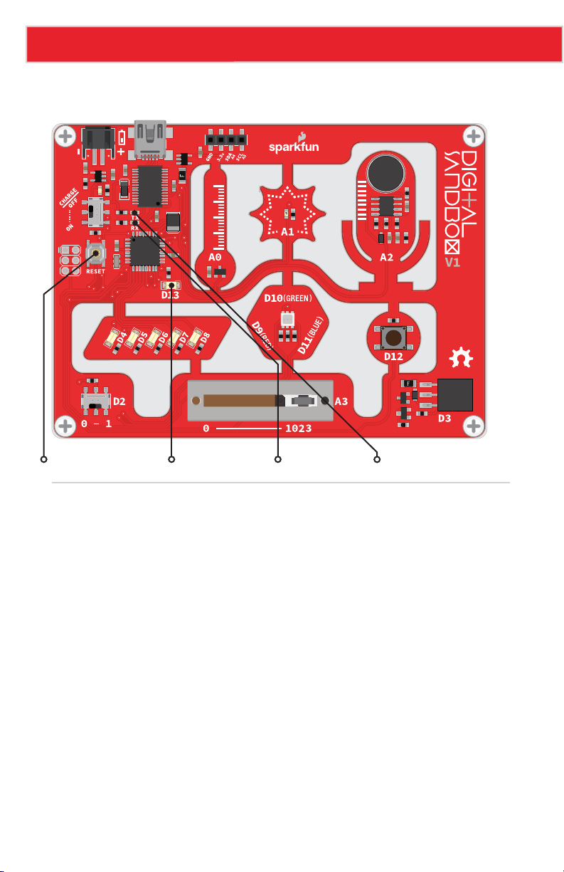
Reset Button LED (D13) LED (RX) LED (TX)
Background Information
This experiment introduces the general concept of physical programming. Changes you make
in your program will actually affect what’s happening on the Digital Sandbox board.
This drawing also serves to introduce a couple of the most fundamental Arduino
programming concepts: setup and loop.
Please note: You can continue with the Code Components section to see what blocks
you will need for this experiment. Each experiment also has its own saved file with all the
experiment’s blocks already set up, so you can get started faster or troubleshoot if needed.
To open this experiment, click the Open button in ArduBlock. Then, go to the Digital
Sandbox Examples folder in the same location where you moved the folder during the
initial setup. From there, you will open the corresponding experiment file. For example,
00_setup_loop_blink.abp is for Experiment 00.
Page 8
Page 10
Experiment 0: Setup, Loop, and Blink
Code Components
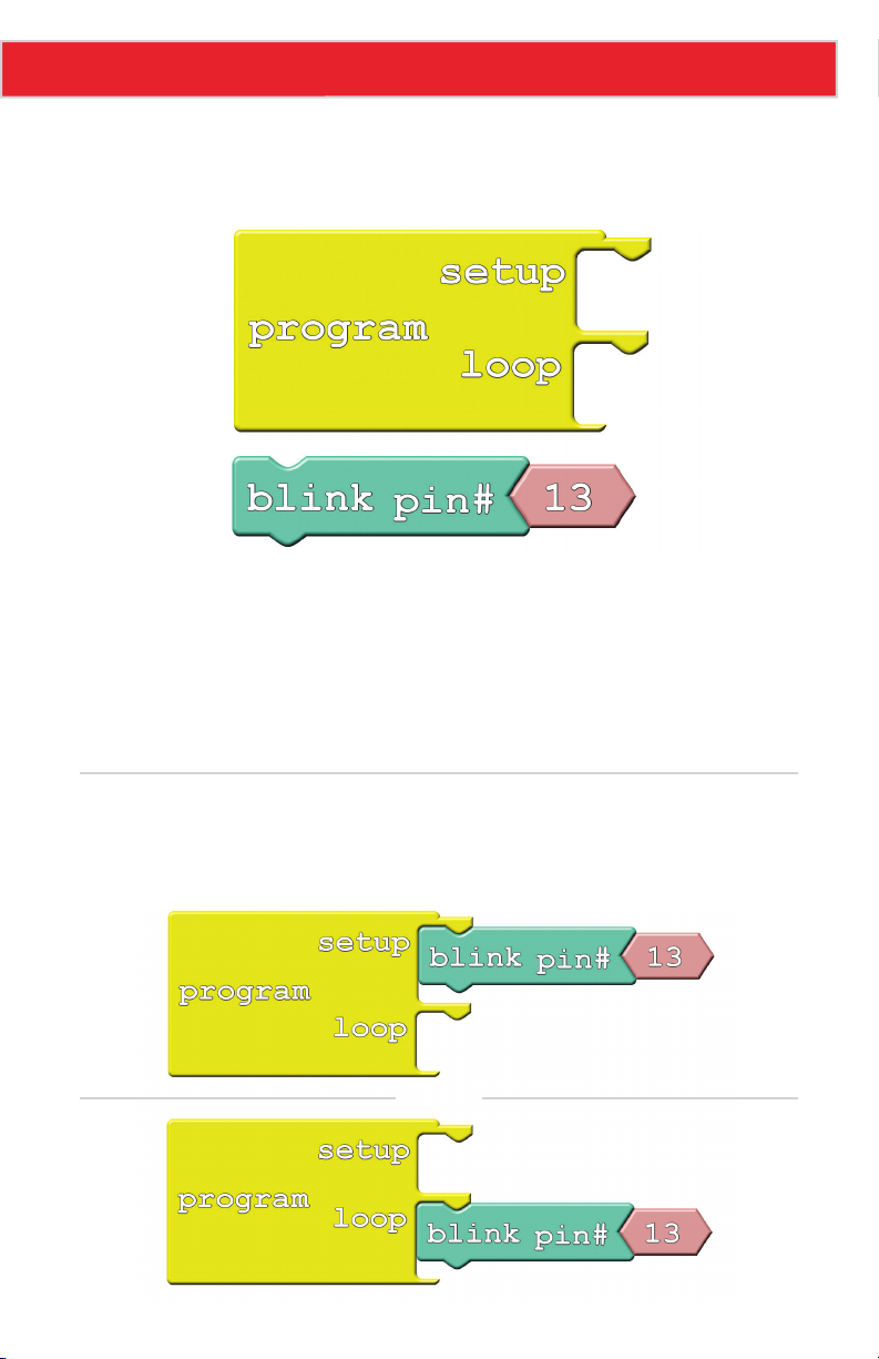
This code drawing requires two blocks (well, sort of three):
• Program: This block is required for every single ArduBlock drawing! You can only have
one per drawing. Program always has two slots for blocks – one named "setup" and
another named "loop." Find this block under the Control bin.
• Blink: Find this block under the Pins bin. This block “blinks” a pin on the Digital
Sandbox. The Blink block actually gives you two blocks for the price of one! It also
includes a pink block with the number 13 inside it. Leave that block alone for now;
we’ll discover its use in later experiments.
Do This
With this pair of blocks, there are only two functional drawings that we can create. You can
either stick the Blink block under the setup section of Program, or under the loop section.
OR
Page 9
Page 11

Experiment 0: Setup, Loop, and Blink
Try sticking the Blink block under setup, then click the Upload to Arduino button.
ArduBlock 00_setup_loop_blink.abp
Upload to Arduino Serial MonitorNew Save Save As Open
Keep your eyes glued to the Digital Sandbox as the code uploads. You’ll see the red and
green RX and TX LEDs blink like crazy as code is sent from your computer to the Digital
Sandbox. Pay extra close attention to what happens after the red and green LEDs do their
dance. Do you notice anything?
Now move the Blink block from setup to loop, and do the Upload to Arduino jig again.
Notice anything different?
Every Arduino program requires that two functions always be present: setup and loop. From
the names of these functions, it should be pretty clear what their job is.
Setup runs once, at the very beginning of the program. Its purpose is usually to set the
platform up for the rest of its lifecycle (until the Sandbox is reset, or loses power). As we
continue on with these experiments, you’ll have a greater understanding of what kinds of
things need to be set up in advance.
If setup sets the Sandbox up, loop must…loop. Code in this block will execute sequentially
and endlessly. Once we get to the bottom of loop, we jump right back up to the top and do it
all over again. This looping will continue until you either reset or remove power.
Further Explorations
• What happens when you press the reset button?
• What happens if there’s nothing in either the setup or loop (move the Blink block out)?
• What happens if you add a second Blink block to the drawing? Regardless of where
you put it, can you discern which of your Blink blocks are being executed?
• What do you think the 13 inside the Blink block is for?
Page 10
Page 12

1: EXPLORING BLINK
Now, we didn’t exactly cheat in experiment 0, but the
Blink block was a bit of a shortcut. What if you wanted
to speed up the blinking? Or change how long it’s on,
versus how long it’s off? Or even blink something other
than that wimpy, little red LED?
Page 13
Experiment 1: Exploring Blink
Active Part
GND
VCC
OUT
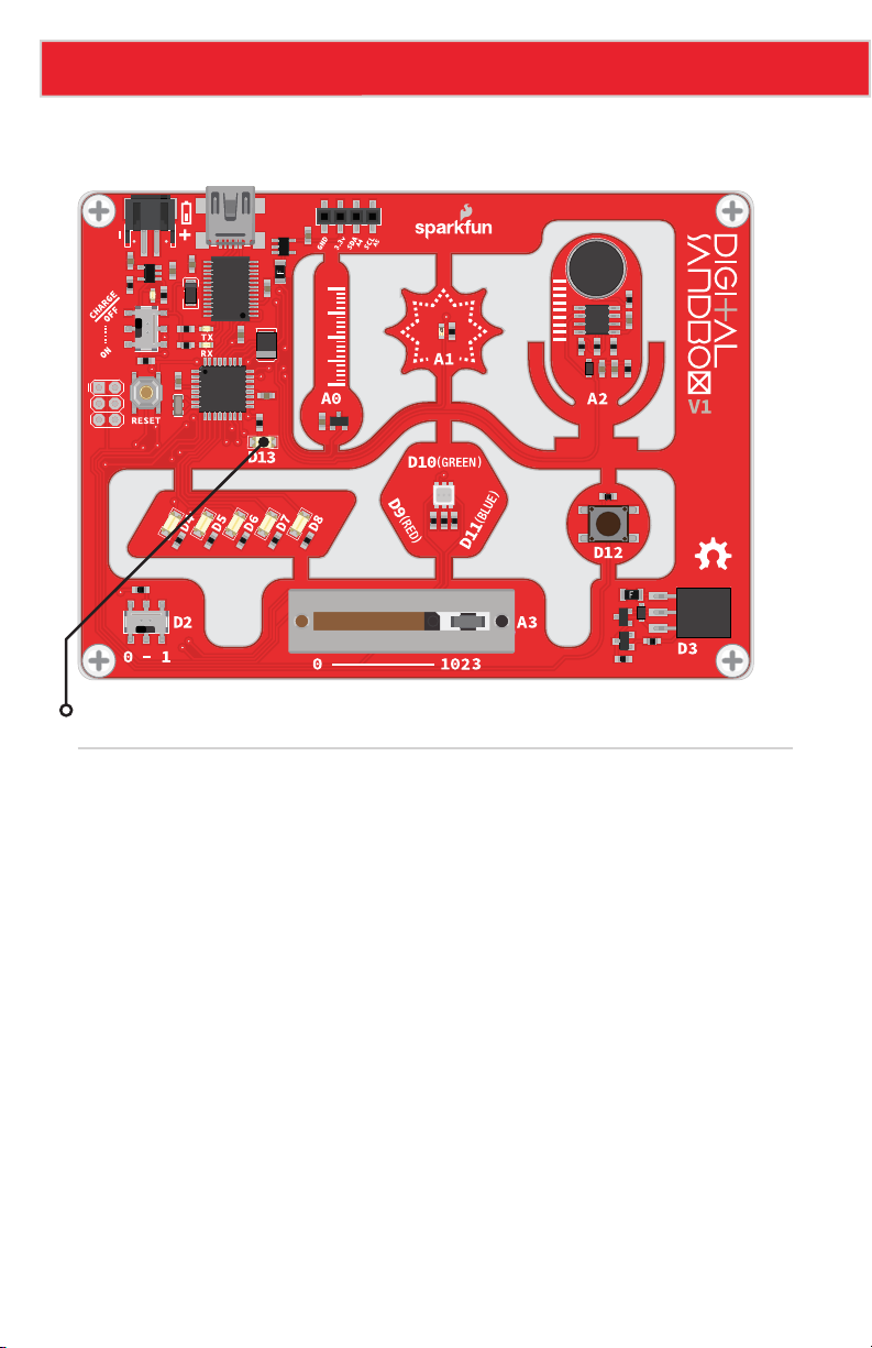
LED (D13)
Background Information
This experiment digs into the anatomy of the Blink block. We can customize an LED blink
with a combination of two blocks – Set Digital Pin and Delay Milliseconds.
This experiment introduces the concept of digital output. We call the Sandbox’s LEDs
“outputs” because it’s an effect that the board produces.
The term “digital” means that the output can only take one of two states: ON or OFF. We
may also refer to those two opposing states as HIGH/LOW or 1/0. When an output connected
to an LED is HIGH, the LED turns on. When the output is LOW, the LED turns off.
Page 12
Page 14
Code Components
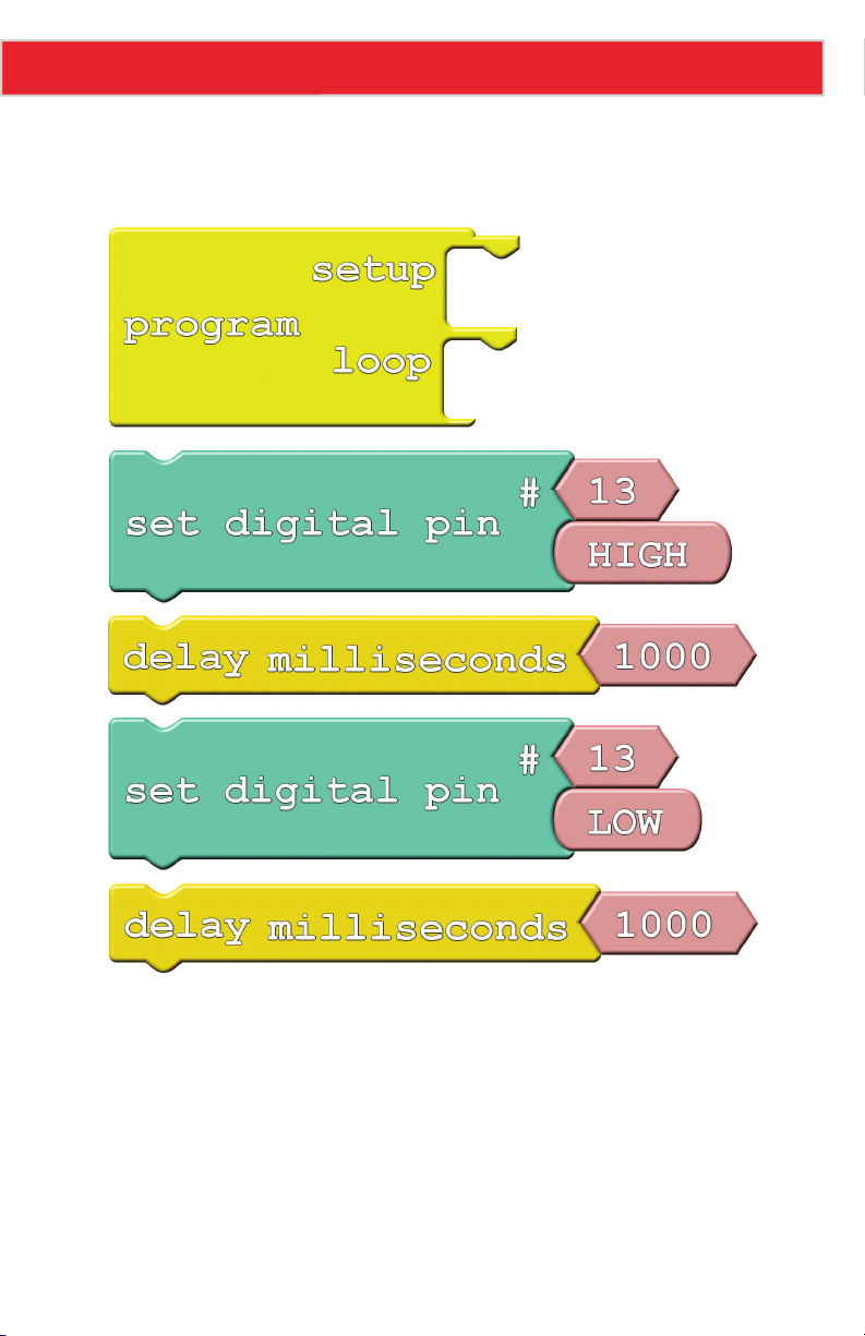
Here is the set of blocks we’ll use to create this drawing:
Experiment 1: Exploring Blink
Aside from Program block, which you should include in every drawing, there are two new
blocks to be added:
• Set Digital Pin: This block sets an output to either HIGH or LOW, so it can be used
to turn the LED on or off. Find this block under the Pins bin. When you drag this block
over, it includes a pair of pink blocks containing “13” and “HIGH.” Let’s only concern
ourselves with the bottom pink block for now.
• HIGH/LOW block: If you mouse over this block, a drop-down arrow will appear. Click
the arrow and you can change the value of the block to either “HIGH” or “LOW.” This
determines which of the two states you’re setting the digital output to.
Page 13
Page 15

Experiment 1: Exploring Blink
• Delay Milliseconds: The Digital Sandbox runs code so fast that sometimes we need
to slow it down with a delay. This block will halt the Sandbox from doing anything for
a specified number of milliseconds. There are 1000 milliseconds (ms) in a second, so
delaying for 1000ms will stop for 1 second. Find this block under the Control bin.
Do This
Organize and snap together the Set Digital Pin and Delay Milliseconds blocks so they
alternate – teal, yellow, teal, yellow. Then put the group of four blocks in the loop section of
the Program block. Then, upload the code.
You should see a very familiar sight. But this time you have control over the blink rate!
Adjust the value in the Delay Milliseconds block(s). What happens if you make the delays
shorter? What happens if the two delays are not for the same amount of time?
The Digital Sandbox operates at 8MHz – there’s a clock in there that ticks eight million
times per second. That means it can run millions of lines of code per second. Without any
delays in the program, the digital output would flick on and off so fast you wouldn’t be able
to tell if it’s actually on or off.
Further Explorations
• How short can you make the delays and still notice a blink (10ms? 1ms?)?
• What happens if you take the Delay Milliseconds block out of the program?
• While digging around for the Delay Milliseconds block, you may have discovered a
Delay Microseconds block as well. What happens if you swap that in?
Page 14
Page 16

2: MULTI-BLINK
Large arrays of LEDs are often used to create massive
outdoor signs and animations, because they're both
bright and efficient. While we don't have the millions
of LED pixels that a display in Times Square might
have, we can still create some fun patterns with the
Digital Sandbox.
Page 17
Experiment 2: Multi-Blink
Active Parts
GND
VCC
OUT
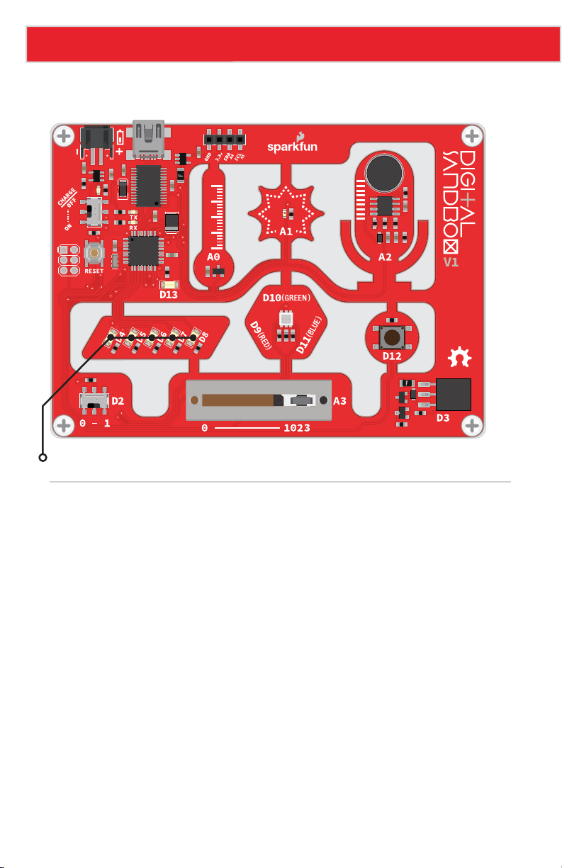
LEDs (D4-D8)
Background Information
In this experiment we explore the subject of pins - the manipulators of the Sandbox. Each
LED (as well as the other inputs and outputs on the Digital Sandbox) is connected to a
specific pin on the Sandbox's microcontroller.
Pins are all uniquely numbered, and each input or output component on the Sandbox is
labeled with the pin number it's connected to - that's the D2, D4, D11, A1, etc. lettering next
to each LED, switch and sensor.
Every pin can be separately controlled; for instance pin 4 can be set HIGH at the same time
pin 5 is set LOW. Some pins (as we'll later discover) have special powers, but every pin is at
least able to accomplish digital input and output.
Page 16
Page 18

Experiment 2: Multi-Blink
Code Components
Whoa! Block explosion! This experiment calls for sixteen total blocks:
Page 17
Page 19
Experiment 2: Multi-Blink
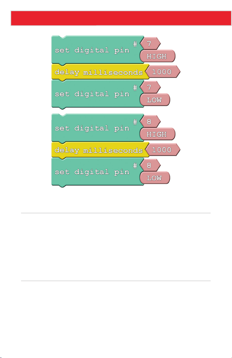
Instead of introducing a new block, we'll be adjusting the value of Set Digital Pin's top pink
Pin Number block. This value specifies which of the Sandbox's pins we'll be toggling.
Do This
In our unfinished example, the blocks are all arranged in groups of three. Each group begins by
setting a pin HIGH, then delays for a second and sets it back to LOW. Notice that each group of
three toggles a different pin, ranging from pin 4 to pin 8. Stack the groups of three on top of
each other in the loop, then upload and enjoy the exciting animation.
If the LED slide is too slow for you, try adjusting the delays to make it faster. Or perhaps you
want to change the pins to adjust the order of the blinks?
Further Explorations
• Try adding more blocks to create slicker patterns. Can you make a Larson scanner (ask
an old person about Cylons or Knight Rider)? A chaser? Flip from odds to evens?
• Try turning on more than one LED at a time. Turn them all on (and shield your eyes)!
Page 18
Page 20

3: DIMMING (THE HARD WAY)
Yikes! Those white LEDs are blindingly bright! Is there
any way to dim them? Unless one of your hobbies is staring
into the sun, we recommend putting a piece of paper
over the LEDs in this experiment…or wear sunglasses.
Page 21
Experiment 3: Dimming (the Hard Way)
Active Parts
GND
VCC
OUT
LEDs (D4-D8)
Background Information
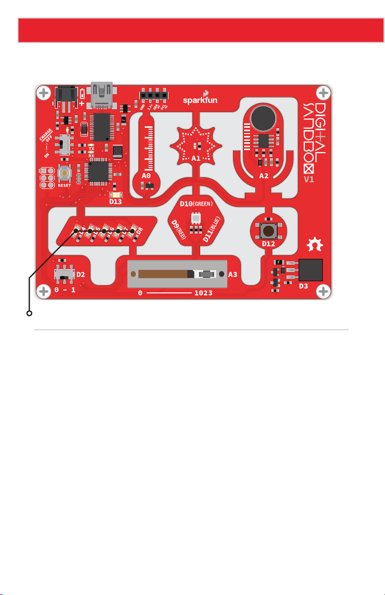
Remember that the Digital Sandbox is fast. It can flick an LED on and off millions of times
per second. What if we blinked the LED super fast, but also made it so the time it’s off was
more than the time it was on? This is called pulse-width modulation (PWM), a tool with a
variety of applications, including the dimming of LEDs.
In this experiment we’ll explore PWM the hard way, by coding it in manually.
Page 20
Page 22
Experiment 3: Dimming (the Hard Way)
Code Components
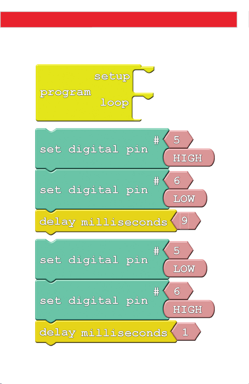
We’ll use a similar set of blocks:
Take note of how long each delay is, and which pins are on/off in each group.
Page 21
Page 23

Experiment 3: Dimming (the Hard Way)
Do This
Stack the two groups of three on top of each other in the loop section, and upload.
After uploading, take a close look at the LEDs connected to pins 5 and 6. Can you spot a
difference between the two? The D6 LED should look dimmer in comparison to D5. That’s
because D6 is set to be low 90% of the time, and on only 10%. It’s blinking on and off so
fast that you can’t notice, and the blinking is creating a dimming effect.
What happens if you swap the two Delay Milliseconds blocks? What if you change the
values in each of the delay blocks (try to keep the sum of delay times to around 10ms)?
Further Explorations
• How long can you make the delays before you start noticing a blink?
• Try comparing both LEDs to a fully-on LED. Add a Set Digital Pin block to the setup, and
have it turn the D4 LED HIGH. Can you tell a difference between D4, D5 and D6?
• What happens if you add something else to the loop section, like your animation from
Experiment 2?
Page 22
Page 24

4: DIMMING (THE EASY WAY)
Manual PWM is hard, and it doesn’t leave room for
anything else in the program. Why can’t we offload
that chore to the Digital Sandbox’s microcontroller? It’s
smart enough for that…right?
Page 25
Experiment 4: Dimming (the Easy Way)
Active Parts
GND
VCC
OUT
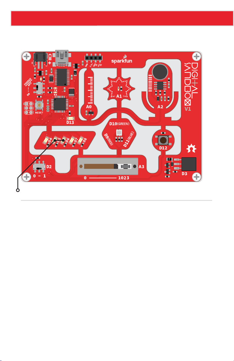
LEDs (D5-D6)
Background Information
PWM is such a popular tool many microcontrollers implement special hardware so they
can mindlessly toggle the pin while doing something else. We call this PWM-based output
"analog output."
Unlike digital outputs, which only have two possible values, analog outputs have a huge
range of possible values. On the Sandbox, we can analog-ly output 256 different values.
If we set an analog output to 0, that’s like setting a pin LOW, and 255 is like setting a pin
HIGH, but all of the values in between produce an output that’s neither HIGH or LOW – it's
somewhere in between.
Analog output seems great – why wouldn’t you use it all the time? Unfortunately, not all pins
have special PWM powers. Only pins 3, 5, 6, 9, 10 and 11 are able to produce analog outputs.
Page 24
Page 26
Experiment 4: Dimming (the Easy Way)
Code Components
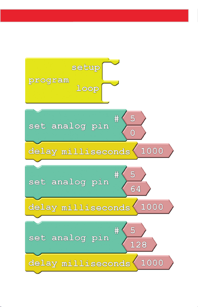
New block alert! While it may look similar, we’ll be using Set Analog Pin this time instead of
its digital counterpart:
Page 25
Page 27
Experiment 4: Dimming (the Easy Way)
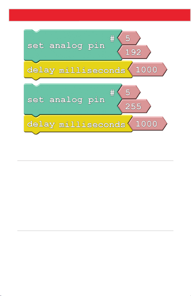
• Set Analog Pin: This block looks a lot like the Set Digital Pin block. We still tell it which
pin to control, but instead of a restrictive, digital output option, we get to choose any
number between 0 and 255 for the output. Find this block under the Pins bin.
Do This
Stack the blocks in the loop section. Order them so the analog values go from 0 at the top to
255 at the bottom. Then, upload away!
The LED on pin 5 should cycle through five different levels of brightness (including fully on
and fully off). Remember that setting the analog output to 0 turns the LED off, and 255 is
like setting it to HIGH.
Try adding analog control of the pin 6 LED to the drawing. You can create the same effect
from the last experiment with just two lines of code (and you can execute other code while
the LEDs remain in their dimmed state).
Further Explorations
• What’s the dimmest value you can assign to the LED and still see it on?
• Why do you think there are 256 possible analog output values? That doesn’t seem like
a very round number (hint: 28).
Page 26
Page 28

5: COLOR MIXING
Bleh…white. So boring. Let’s add some color to this
Sandbox! By combining analog output with an RGB
LED, we can mix varying levels of red, green and blue
to create a rainbow of colors!
Page 29
Experiment 5: Color Mixing
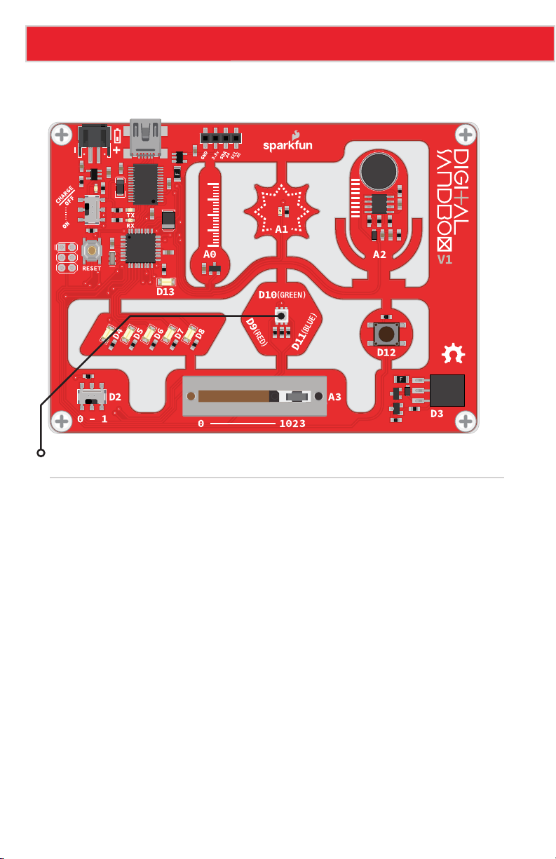
Active Part
GND
VCC
OUT
RGB LED
Background Information
In art class you probably learned about primary colors and how you can mix them to
produce any other color. While the artsy primary colors you might be familiar with are red,
yellow and blue, in electronics (and programming in general), our primary colors are red,
green and blue.
By selecting different analog levels for our primary colors, we can mix them to create
any other color we want. Need yellow? Mix green and red. Purple? Red and blue. In this
experiment we’ll combine everything we’ve learned about analog output to add custom color
to the Digital Sandbox.
Page 28
Page 30
Experiment 5: Color Mixing
Code Components
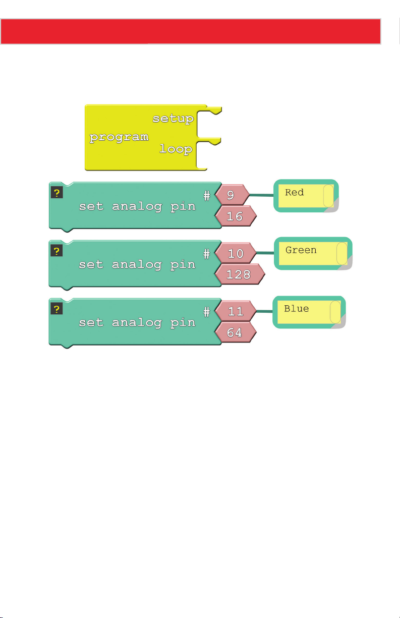
For the most basic RGB color-mixing sketch, this is all we need:
In the example, we added comments to each of the Set Analog Pin blocks. Comments
have no effect on the actual code, but they do help make the code more readable to you or
others. With those blocks commented, we don’t have to look back at the board to remember
which pins go to which colors.
You can add comments by right-clicking on a block, and selecting “Add Comment.” Show or
hide comments by clicking the question mark.
Page 29
Page 31

Experiment 5: Color Mixing
Do This
Stack those three Set Analog Pins on top of each other, in either the setup or the loop.
This will set red’s value to 16, green to 128, and blue to 64. What color do you think it’ll
make? Upload to find out (if it’s hard to tell what the color is, put a piece of paper over
the RGB LED).
Play with the analog values to make your own colors. How about purple, or orange, or
salmon? You can take it even further by adding delays, and blinking different colors to
make animations.
Further Explorations
• Mix the colors to make your favorite color. Or, if your favorite color is red, green or blue,
try making your least favorite color.
• Make a stop light blink from green, to yellow, then quickly to red and repeat.
Page 30
Page 32

6: NUMBER STORAGE
WITH VARIABLES
The herky-jerky fading from Experiment 4 accomplished the
task, but just think of all the values we were missing!
How do we make the LED fade smoothly? You can whip
out 256 minutely different Set Analog Pin blocks, or you
can reduce it to one, using variables.
Page 33
Experiment 6: Number Storage with Variables
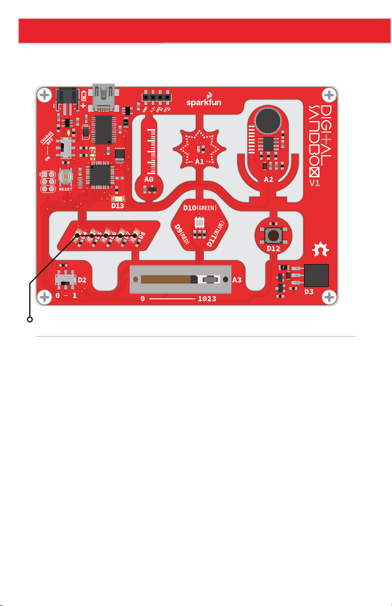
Active Parts
GND
VCC
OUT
LEDs (D4-D8)
Background Information
Variables are like storage containers for numbers. We can put any number in a variable, and
either recall it and put it to use, or manipulate it to change the value it stores. Anywhere you
stick a literal number (like “0” or “255”) you can instead use a variable.
There are a few rules when it comes to creating a variable. They can be any word, but
they must begin with a letter, and they can’t have spaces (use “_” instead). They are
case sensitive, so a variable named “fade” isn’t the same variable as “Fade.” Try to keep
variables short, but use descriptive words to keep your code legible.
Page 32
Page 34
Experiment 6: Number Storage with Variables
Code Components
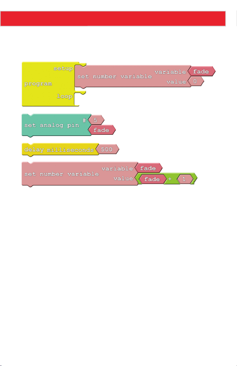
Thanks to variables, here are all the blocks we need to create a smooth fade:
There are a few new blocks to familiarize yourself with this time:
• Number Variable Name: These blocks are about the same size and shape as the
literal number blocks we’ve been using. But, instead of writing a number in these
blocks, you type in the name for your variable. Make sure it’s spelled the same in
every place you want to reference it! You can find this block under the Variables/
Constants bin on the left.
• Set Number Variable: This block, also found under the Variables/Constants bin, is
used to set a variable to a specific value. Two blocks snap to this one – a variable
name on top, and the value you want to set that variable to on the bottom. The value
can be a literal number, another variable, or the result of a mathematical operator.
• Math operator block: If you click on the Math Operators bin and look at the first
four entries, you should see some very familiar symbols: +, −, ×, and ÷. These math
operators can be used to do math on a pair of variables, numbers, or a combination of
the two.
Page 33
Page 35

Experiment 6: Number Storage with Variables
Do This
Add the first Set Number Variable block, which will include a blank variable and a value.
Click into the number variable name and write “fade” into it. The “fade” variable will keep
track of the the brightness of our LED. The Set Number Variable block in the setup area of
the program should set the “fade” variable to 0.
You should be familiar with Set Analog Pin and Delay Milliseconds; grab those blocks and
stick them in the loop in either order.
We’ll need to throw away the value block that comes with Set Analog Pin (drag it over
to the left side of the window) and replace it with a variable. To add a variable to your
sketch, drag over the Number Variable Name block and type your variable’s name into it.
Alternatively, once you’ve made one variable, you can right-click on it and clone it to get
more of the “fade” variables you’ll need.
Finally, add another Set Number Variable block, and replace the 0 value it includes with a +
operator. Modify it so it adds a 1 to “fade,” and plug it into the value part of the Set Number
Variable block. Then stick that block group at the end of the loop.
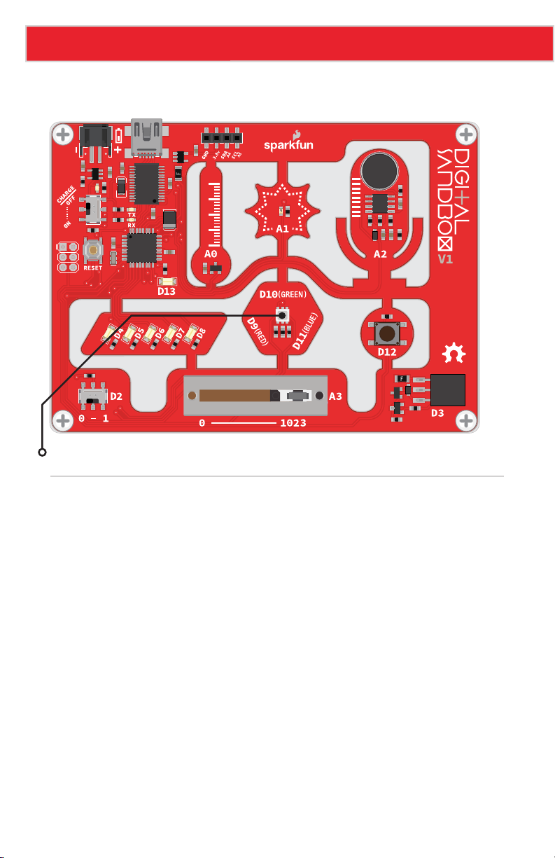
Whew! Let’s see what all that work was for by uploading the drawing. The LED on pin 5
should satisfyingly and smoothly flow from fully off to fully on.
Further Explorations
• Does it matter what order you have the loop blocks in?
• Can you make other LEDs fade? How about more than one fading at the same time?
• Can you make the LED fade from HIGH to LOW? Hint: You may need to change the
setup value of “fade,” and change the + to a −.
Page 34
Page 36

7: IF THIS, THEN THAT
Fading from the last experiment was working just fine
until we got to the maximum brightness level of 255.
What happens then is a mystery known only to the
compiler (and you, once you learn a little something
about data types). What if we added “catch” to force
that fade variable to reset when it hits a certain value?
Page 37
Experiment 7: If This, Then That
Active Part
GND
VCC
OUT
RGB LED
Background Information
This experiment introduces the if statement, one of the most fundamental programming
structures. Not only are if statements important for computers, they also rule most of the
decisions we make in our lives. If it’s cloudy outside, then pack your umbrella. If you’re
hungry, then make a sandwich. Like us, computers use if statements to make choices.
An if statement requires two components to be complete: a condition and a consequence.
A condition is a value or mathematical operation that evaluates to either true or false. If the
condition evaluates to true, then the consequence is executed. The consequence can be a
code block of any size – one block or hundreds of blocks.
If the condition in the if statement is false, then the consequence is skipped, and the
program starts running the code following the If block.
Page 36
Page 38
Experiment 7: If This, Then That
Code Components
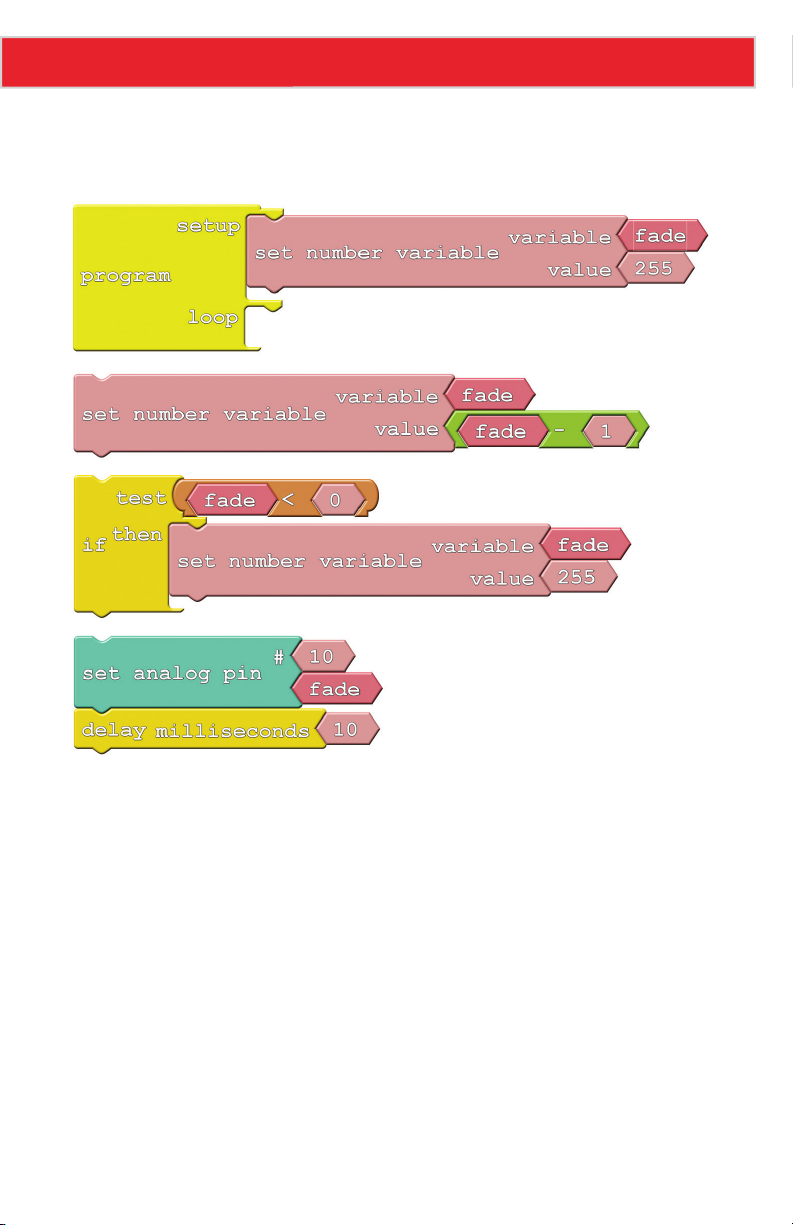
Here are the blocks required to limit the fade value of our LED:
There are two new blocks to mention here:
• If: The star of this experiment can be found under the Control bin. The If block requires
at least two blocks to be snapped into it: a conditional and the consequence. In this
case, the consequence is just a single block – Set Number Variable. The conditional
part of the If block is a logical operator block.
• Logical Operator: Logical operators are symbols which operate on one or two values
and evaluate to either true or false, which makes them perfectly suited for the if
statement conditional! In this case we’ll be using the less than (<) operator. If the
value to the left of the < symbol is less than the value on the right, then the operator is
true. If the left is not less than (either greater than or equal to), then the condition will
evaluate to false.
Page 37
Page 39

Experiment 7: If This, Then That
Do This
In this sketch, we want the green LED to progress from super-bright to off, and repeat that
cycle endlessly. We’ll use a variable called fade to keep track of the analog output value.
At the very beginning of each loop, we’ll subtract 1 from the fade variable.
Then, after subtracting from fade, we need to use an if statement to make sure it’s not out
of bounds. The if statement in this sketch states that if fade is less than 0 (that would
mean it’s a negative number), then set fade to 255.
Once we’ve generated our fade value, we can set pin 10 (or pick another LED if you please)
to that analog output value.
Snap together the Set Number Variable, if and Set Analog Pin block groups. Then put the
group in the loop section of the Program block.
Now upload and enjoy a nice, controlled fade.
Further Explorations
• Can you make the fade work the other way? Start at 0, fade up to 255, and then go
back to 0. Hint: you’ll need to flip the logical operator around.
• Make it even smoother! Can you make it fade smoothly up and smoothly down in
the same sketch? From 0 to 255, then 255 to 0, then 0 to 255, then back again.
Page 38
Page 40

8: THE REACTION TESTER
Computers are great at doing math and automating boring
tasks, but everyone knows that their true purpose is to play
games. Let’s create a game on the Digital Sandbox! In order
to control the game, we need to add input.
Page 41
Experiment 8: The Reaction Tester
Active Parts
GND
VCC
OUT
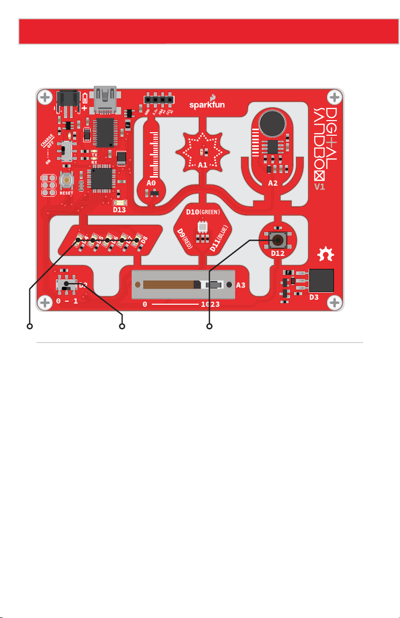
LEDs (D4-D8) Slide Switch Push Button
Background Information
Up to this point, our Digital Sandbox experience has been very one-sided: output to tiny
yellow LEDs, output to larger white LEDs, output to RGB LEDs, change the fade value of the
output. Output, output, output. Let’s flip the tables on the Sandbox and send some input to
the board!
Inputs are signals or values sent into a system. Some of the most common inputting
components are buttons. Buttons on a keyboard are an input to your computer, because
they send data into that system.
An if statement is critical to assessing the status of an input and taking an action based
on it – if button A is pressed, then print an “a.” We can take the if statement a step further
by adding an else condition, which allows us to control what happens if the if statement
evaluates to false. So now we can say something like, “If the egg floats, throw it away;
otherwise (else) fry it and eat!”
Please note: This experiment has a lot of blocks. Remember you can also open this
experiment from the Digital Sandbox Examples folder, so you can get started faster or
troubleshoot if needed.
Page 40
Page 42
Experiment 8: The Reaction Tester
Code Components
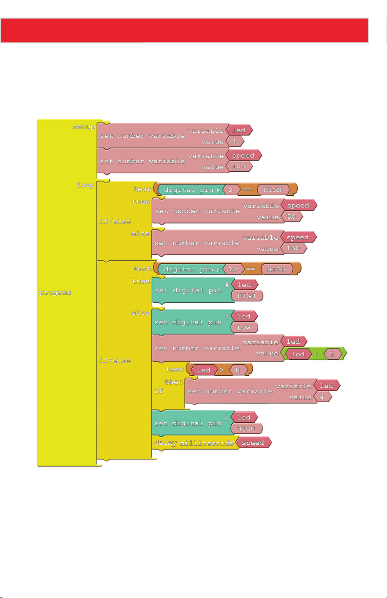
Our game will use both the switch (in the bottom left of the Sandbox) and the small button
– components tied to pins D2 and D12, respectively. The sketch is pretty massive, so we’ll
snap it together for you. Here’s what it looks like:
• If/Else: This block works just like the If block, but it allows you to determine what happens
if the conditional evaluates false in addition to true. Again, you need a conditional block (or
set of blocks) that evaluate to either true or false in the test snap. You also need to add two
separate blocks of code to fill both the then and else snaps.
• Equivalence test (==): To test if two values are equivalent, we use the == statement.
That’s right, there are two equals signs. This is to differentiate from a single equals sign,
which is used to set one value to another. The double equals is like asking, “Are these two
values equal?”
Page 41
Page 43

Experiment 8: The Reaction Tester
Do This
Arrange your blocks so they match the image in the Code Component section. There are
two important if/else statements in this program; each tests the status of an input. The
top If/Else tests pin 2, which is connected to the switch. If the switch is set to 1 (e.g.
HIGH), then we set a variable called speed to 50. If the switch is set to 0 (LOW), then
speed becomes 150.
The second If/Else tests pin 12, which is tied to the small button. When the button is
pressed, then the input is set to 1 (HIGH), and it’s 0 when released. This means that when
the button is being pressed, the code in the then will execute. When the button is not being
pressed, the else blocks will run.
Can you guess what will happen in each of the pin 12 test cases? Upload the sketch to your
board to find out!
This is a very simple game. Pick a number between 4 and 8, and try to make the LED stop
on that number by pressing the button. To switch between easy and hard mode, move the
switch from 0 to 1. Can you make it stop in the middle on hard mode?
Further Explorations
• Trick your friend and swap which direction of the switch sets it to easy mode – make 0
hard and 1 easy.
• Swap the function of the switch and the button. Make it so you have to press the
button to set the difficulty, and flick the switch to stop the LEDs.
Page 42
Page 44

9: SERIAL CALCULATOR
While you probably can’t have a very stimulating
conversation with the Digital Sandbox, it can send
you some very interesting information. It’s great at
math, so let’s have the Sandbox do some calculating
for us! Trouble is, how do we get it to print numbers
(without Morse code)? Enter serial communication!
Page 45
Experiment 9: Serial Calculator
Active Part
GND
VCC
OUT
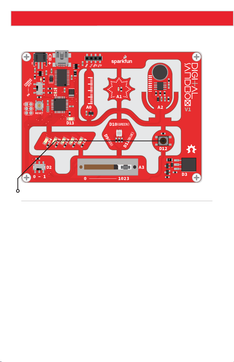
Push Button
Background Information
Serial communication is a form of data transmission where we can send a string of
1’s and 0’s between two devices that actually forms a set of characters. So 01101000
01100101 01101100 01101100 01101111 00101100 00100000 01110111 01101111
01110010 01101100 01100100 becomes “Hello, world.”
With serial, we can send actual text from the Sandbox and display it on our computer using
the Serial Monitor.
Page 44
Page 46
Experiment 9: Serial Calculator
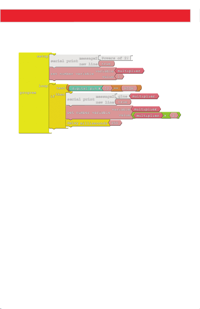
Code Components
Here is the layout for this experiment:
There are two new blocks this time, both of them shaded white and located under the
communication bin:
• Serial Print: This block takes two parameters. At the top, place the message you want
to print. You can put anything you want into the message block (even spaces!). If you
want to add a variable or number, you’ll need to add some glue. The bottom snap of
Serial Print determines if a new line is printed after the message. Usually you’ll want
this to be set to true.
• Glue: Glue blocks allow you to print values like variables or numbers – anything that
isn’t a message you’ve written in. If you want to print a variable, you’ll need to add a
Glue block between the variable and the Serial Print block. There are three different
kinds of Glue blocks, each with a different snap shape on the right. This time we’ll use
the block with a wedge (<) termination.
Page 45
Page 47
Experiment 9: Serial Calculator
Do This
At the very beginning of our sketch, we want to print a friendly message. How about a short
description of what our calculator is going to do: “Powers of 2!” Then set up a variable we
can do some math on, starting at 1.
In the loop, we only want to do math and print when the button is pressed. So, begin by
adding an If block to check whether pin 12 is HIGH (button is pressed). If the button is
pressed, we’ll do our math and print out the result. To print a variable, we need to glue it
to the Serial Print block with a wedge-shaped glue piece. Make your drawing match the
one above.
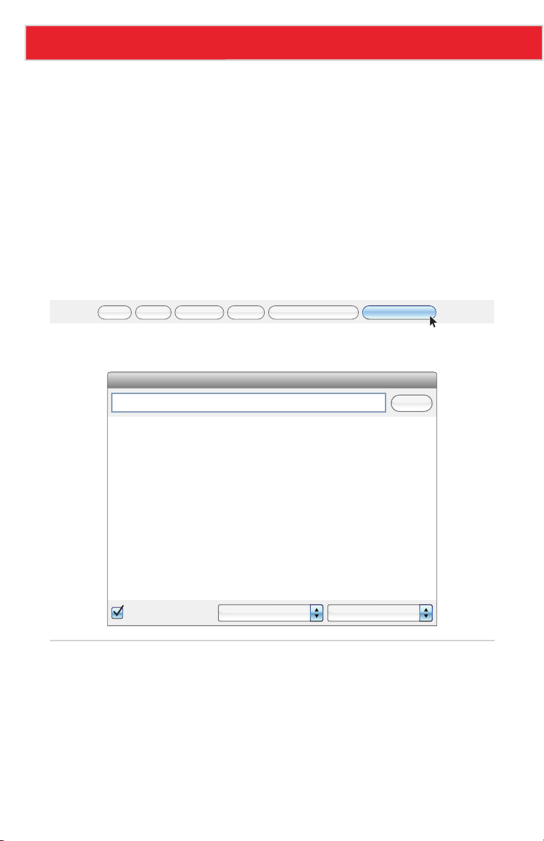
With that, upload the sketch to your Sandbox. Then, to view the serial prints, click on the
Serial Monitor button up top.
Upload to Arduino Serial MonitorNew Save Save As Open
You’ll see your message printed. Now press the D2 button to start calculating.
Send
Powers of 2!
1
2
4
8
16
32
64
128
256
512
1024
2048
Autoscroll
No line ending 9600 baud
Further Explorations
• Something funny happens when the power of 2 gets past 16834, and then turns to
-32768, and then turns to 0. This is because our variable has reached its maximum
value and has, in a sense, gotten confused. Can you add an if statement to catch an
out of bounds multiplier variable and reset it?
• Try some of the other mathematical operators. You’re probably familiar with +, −, ×,
and ÷, but what does the % operator do?
Page 46
Page 48

10: DO THE ANALOG SLIDE
Digital inputs, like the button, only allow for two input
values: HIGH or LOW. But what about the in-betweens?
When you turn the volume up on your stereo, you’re not
forced to pick between mute and "OW MY EARS." For
volume control and other “finely-tuned” settings, we
need analog inputs.
Page 49
Experiment 10: Do the Analog Slide
Active Part
GND
VCC
OUT
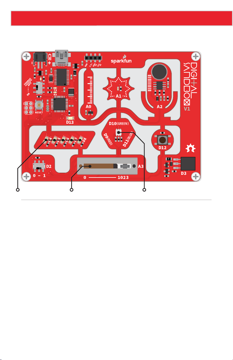
LEDs (D4-D8) Slide Potentiometer RGB LED
Background Information
Analog inputs are components that put data into a system with a range of more than two
values. On the Digital Sandbox, analog inputs can produce a value anywhere between 0
and 1023 (1024 total values). The value produced by an analog input is proportional to the
voltage it produces. If an analog component reads a value of 0, the voltage is 0V. If the
output value is 1023, then the voltage is 5V. An analog reading of 512 is about 2.5V, and
so on.
A special component inside the Sandbox’s microcontroller called an analog-to-digital
converter (ADC) is able to convert that range of input voltages to a discrete number. This is
a special circuit that most pins on the Sandbox don’t have. It’s so special that the ADC pins
are labeled with a preceding "A." The analog sensors on the board are labeled as “A0,”
“A1,” “A2” and “A3.”
Many electronic components produce analog output, the most common of which is a
potentiometer. “Pots” come in a variety of shapes and sizes. Rotary pots are commonly
used to adjust the volume on a stereo. Slide potentiometers, like that on the bottom of the
Sandbox, are often seen adjusting sound levels on mixing boards.
Page 48
Page 50
Experiment 10: Do the Analog Slide
Code Components
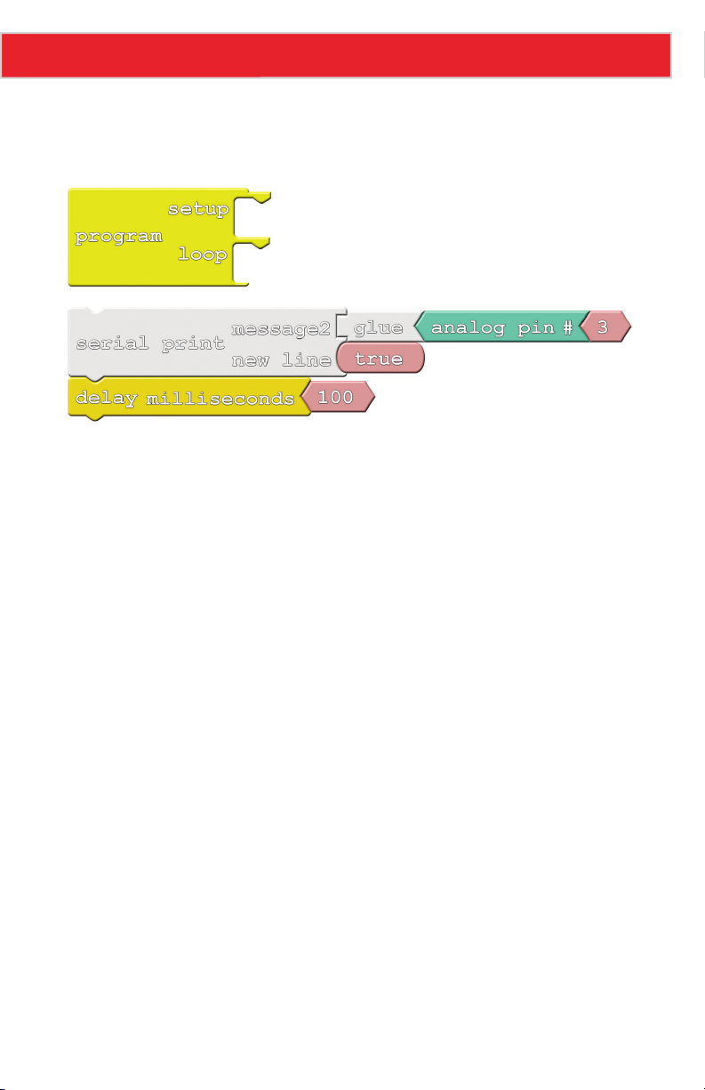
Whew, after that last experiment it’s time for an easy drawing:
• Analog Pin #: Like the Digital Pin block, this block reads in the value of an input.
But, instead of producing either true or false (1/0, HIGH/LOW), this block produces a
number between 0 and 1024. The pink block snapped to the right of this one indicates
which analog pin should be read.
Page 49
Page 51

Experiment 10: Do the Analog Slide
Do This
Snap the block group that starts with Serial Print into the loop section of Program, then
upload and open the serial monitor.
Every 100ms an analog input value should be printed. Move the analog slider to adjust the
value. Can you make the output 0? 1023? 512? Take note of which slide pot position relates
to which value.
Further Explorations
• Can you make the slider control the LEDs? You could slide the white LEDs back and
forth, or try controlling the brightness of the RGB LEDs with the slider.
• Why are there only 1024 output values? Why not an even 1000? (Hint: 210)
Page 50
Page 52

11: AUTOMATIC NIGHT LIGHT
We now have all the programming tools we need to
make some totally awesome, interactive projects. Let’s
incorporate the light sensor – another analog input
component – to create an automatic night light that
turns on when it’s dark.
Page 53
Experiment 11: Automatic Night Light
Active Parts
GND
VCC
OUT
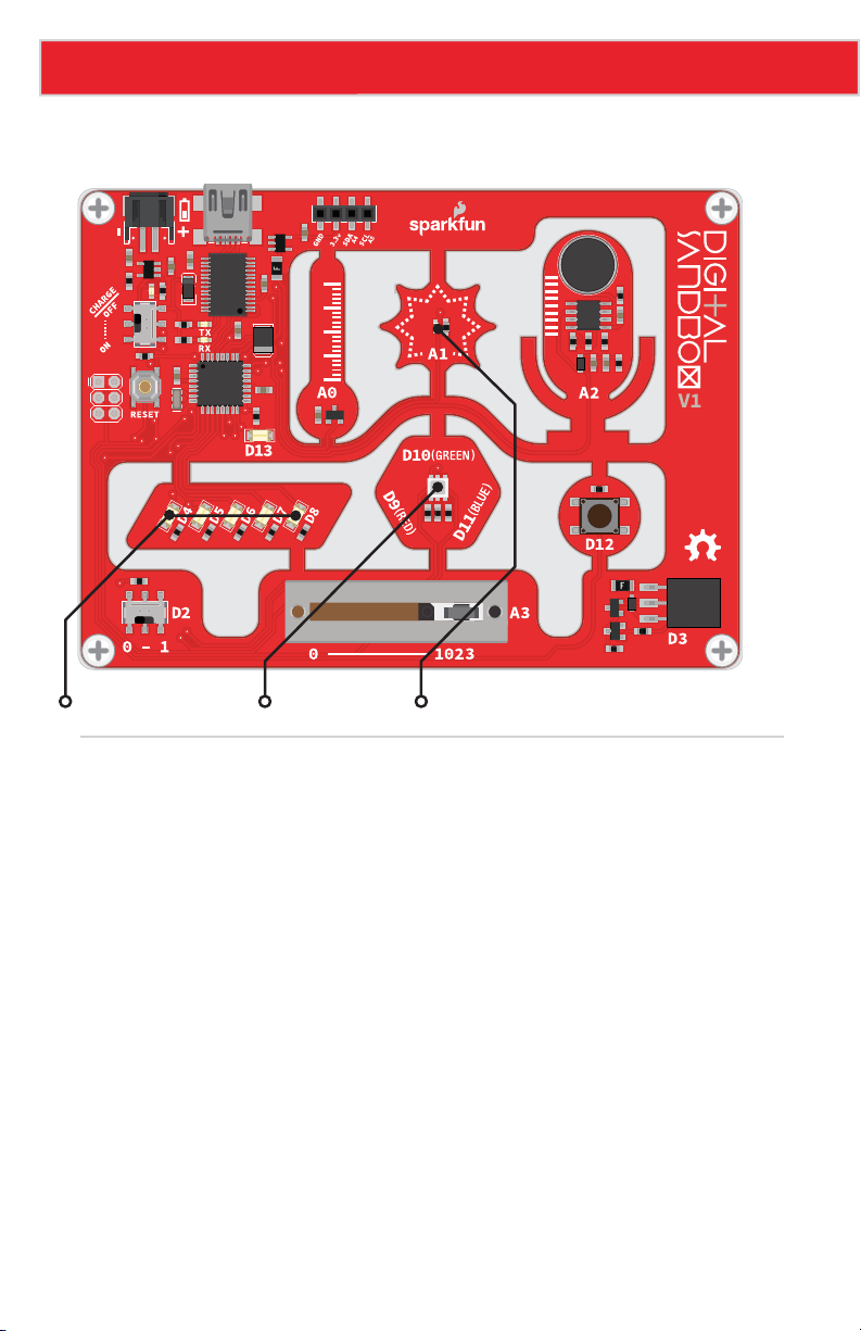
LEDs (D4, D8) RGB LED Light Sensor
Background Information
You may not see them, but light sensors are incorporated into all sorts of modern electronic
devices. There are light sensors in smartphones that measure how bright your environment
is and adjust the screen brightness accordingly. There are light sensors in smoke detectors
that detect particles in the air. Photogates use a light sensor to determine when an object
passes a certain point – great for those photo finishes!
The light sensor on the Digital Sandbox is called a photo-transistor. It produces an analog
voltage relative to the amount of light it sees. The lower the analog value, the darker the
environment. If you cover the sensor completely, you might get the output all the way down
to 0. Shine a flashlight on it and you might get a maximized reading of 1023.
Page 52
Page 54
Experiment 11: Automatic Night Light
Code Components
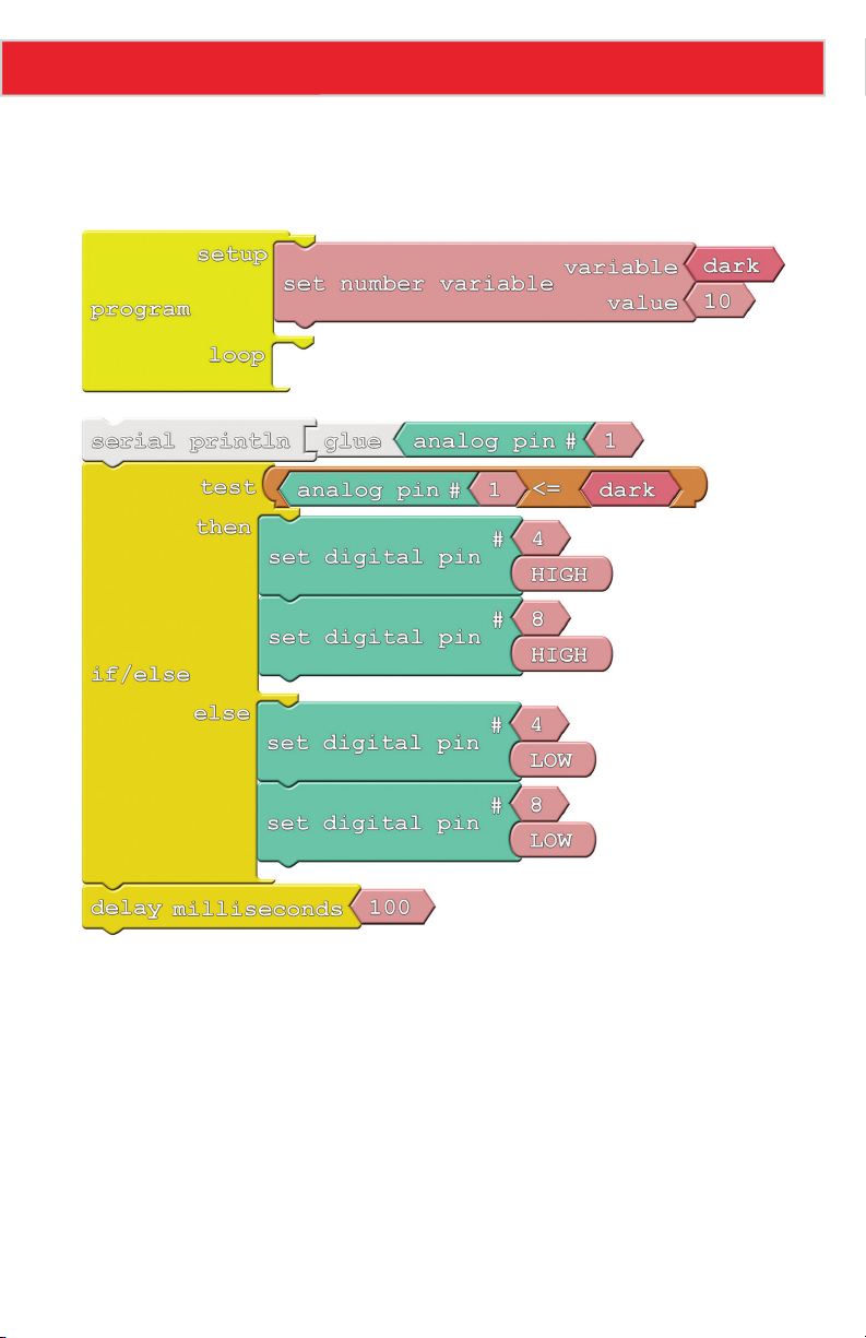
Here is the code block setup for this experiment:
There aren’t any new blocks, but we may have to adjust the value of the dark variable to make
the night light work perfectly. That’s where serial communication will come in handy!
Page 53
Page 55

Experiment 11: Automatic Night Light
Do This
Snap the block group that starts with Serial Println into the loop section of Program. With
that, upload the sketch to your Sandbox.
The trick to this experiment is finding the perfect setting for the dark variable. If your room
is nice and bright, the white LEDs on pins 4 and 8 should be off. When the lights are off (or
the sensor is covered), the LEDs should light up.
If the lights aren’t behaving properly, that’s OK! You just need to fine-tune the dark variable.
Open up the serial monitor to view the output of the light sensor. Take note of the sensor’s
reading when the lights are on, then turn the lights off. What are the values now? Try setting
the value of the dark variable just a bit higher than that.
Further Explorations
• If the brightness is right on the border of on/off, the LEDs can blink unpleasantly. Try
adding another if statement to catch whether the light sensor is right in the middle
range, then you can dim the LEDs based on what the sensor reads.
• Try incorporating the RGB LED into this project. If it’s super-bright, make it light up
yellow. Kind of dim? Green. Totally dark? Blue.
Page 54
Page 56

12: THERMAL ALERT!
“Is it hot in here, or is it just me?” Using a temperature
sensor, which is able to precisely measure the room
temperature, we can answer that question once and
for all!
Page 57
Experiment 12: Thermal Alert!
Active Parts
GND
VCC
OUT
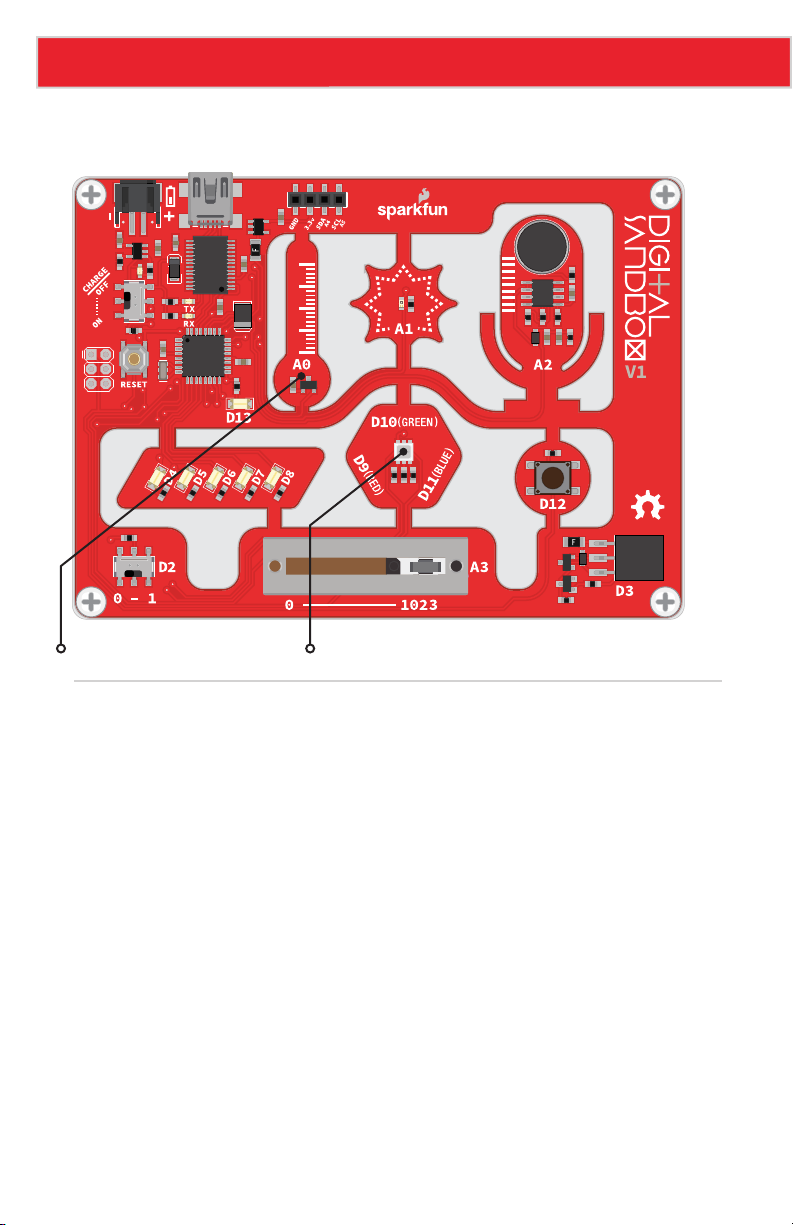
Temperature Sensor RGB LED
Background Information
Temperature sensors are a critical component in many circuits, whether you’re controlling
an A/C system or creating a safety mechanism for gas-powered appliances. Electronic
temperature sensors come in many form-factors, from big thermocouples that can measure
up to 1000°C, to that little black rectangle on the Digital Sandbox.
The temperature sensor on the Sandbox produces an analog voltage that represents
the temperature around it. The voltage is actually linearly proportional to the Celsius
temperature. If you know the output voltage of the sensor, you can calculate the temperature
with this equation:
temp = (voltage - 0.5) x 100
We can have the microcontroller do all of that math for us as long as we find the right
algorithm – an equation or set of instructions that accomplish a specified task.
Please note: This experiment has a lot of blocks. Remember you can also open this
experiment from the Digital Sandbox Examples folder, so you can get started faster or
troubleshoot if needed.
Page 56
Page 58
Experiment 12: Thermal Alert!
Code Components
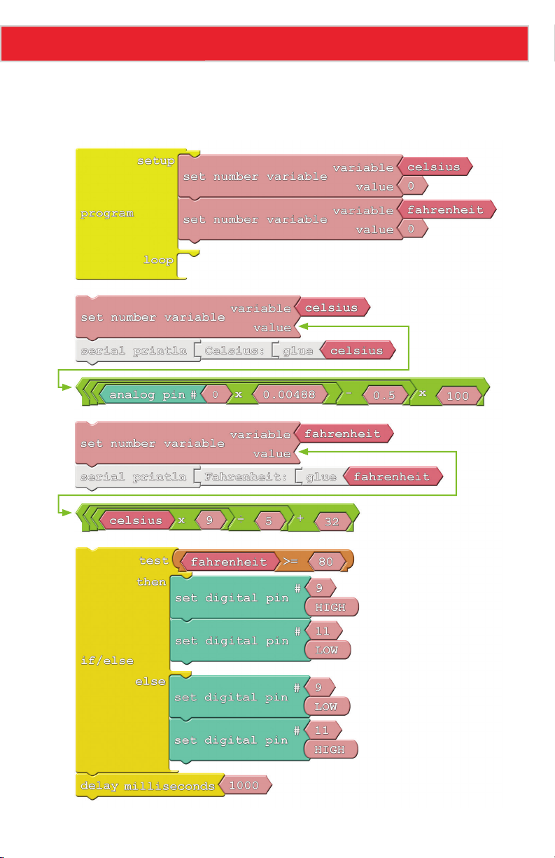
We warned you that there’d be a lot of math on this one; here’s the setup:
Page 57
Page 59

Experiment 12: Thermal Alert!
There aren’t any new blocks here, but as you can see, we do get to use a wide variety of
mathematical operators. Pay close attention to the order of operations. When you have a
series of nested mathematical operators, the innermost operation is calculated first.
Do This
Construct the drawing as shown in the Code Component section. Make sure the
mathematical operations are in the right order! Also important is the decimal point (e.g.
“.0048,” and “.5”) on most of the numbers in these equations. Those tell the microprocessor
that you want it to use extra precision when calculating.
There will be two different groups of mathematical operator blocks. Snap the right
mathematical operator group block to the corresponding Set Number Variable block’s value.
Then, snap the two Set Number Variable block groups above the If/Else block group. You
should have one big set of blocks that will go in the Program block’s loop.
After you’ve completed the drawing, upload the sketch and check out the RGB LED. Is it red
or blue? If it’s red, you’re probably plenty toasty, as your room temperature is above 78°F. If
it’s blue, try warming up the sensor by blowing on it. Can you get it to turn red?
To find the exact temperature reading, open up the serial monitor. After viewing the values
here, you may want to alter the value of the 80 in the if/else test.
Further Explorations
• Can you add a third check to alert when it’s too cold by turning on the blue LED? The
real trick here is cooling the Sandbox off. One option is to power the board with a
battery and stick it in the fridge.
• Celsius and Fahrenheit are two of the most common temperature scales, but they’re
not the only ones. Can you print the temperature in units of Kelvin or Rankine? You’ll
need to find an algorithm to convert to them from Celsius.
Page 58
Page 60

13: SOUND DETECTING
Introducing the amazing, groundbreaking SOUND
(Sandbox’s Over/Under Nominal Decibels) System! With
the SOUND you’ll always have an adjustable sound level
detector handy.
Page 61
Experiment 13: Sound Detecting
Active Parts
GND
VCC
OUT
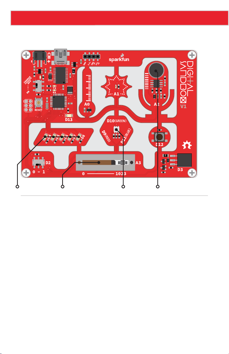
LEDs (D4-D8) Slide Potentiometer RGB LED Microphone
Background Information
In this experiment we’ll use the Sandbox’s on-board microphone to measure volume
levels and display them on the LEDs. The microphone produces a sound wave which is just
another analog voltage we can measure. The louder the sound, the higher the amplitude of
the wave and the larger the voltage.
Without a lot of complicated math and filters, sound can be a difficult thing to measure
and react to. Using the Sandbox for voice recognition isn’t quite possible, but it can be
programmed to pick out high volumes as long as it can sample the microphone input fast
enough. We can use the slide potentiometer to set the sensitivity of the display.
Page 60
Page 62
Experiment 13: Sound Detecting
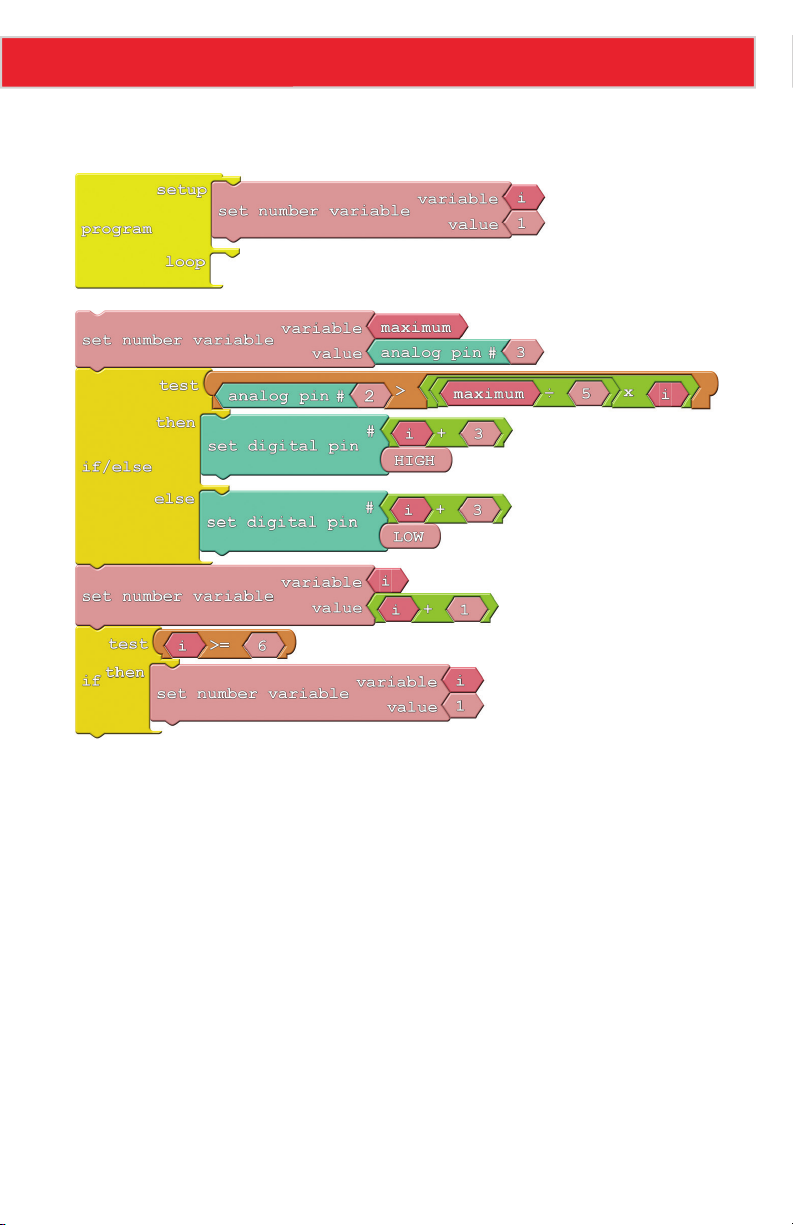
Code Components
Page 61
Page 63

Experiment 13: Sound Detecting
Do This
Snap the large block group starting with Set Number Variable block into the loop section
of the Program block. After arranging the blocks, upload the sketch and have a look at the
LEDs. Are they bouncing to your voice? If not, try tapping on the mic.
To adjust the sensitivity of the volume meter, move the slide pot up or down. With the
slider set to the far right, it’ll take a really loud sound to make every LED turn on. But if you
set the slider too low even the slightest noise will set the meter off.
Further Explorations
• Can you rewrite the sketch to use the RGB LED instead of the white LEDs? Can you
make it turn red when the volume is really loud and turn blue and/or green otherwise?
Bonus points for using analog outputs!
Page 62
Page 64

14: OPTO-THEREMIN (ADD-ON)
In this experiment we’ll attach a buzzer to the Sandbox
and turn it into a musical instrument! By using the light
sensor to control our buzzer’s pitch, we can create a
light-controlled theremin – a non-contact, electronic
instrument.
This experiment is bonus material to be used with the
Digital Sandbox Add-on Kit, which is sold separately.
Page 65
Experiment 14: Opto-Theremin (Add-on)
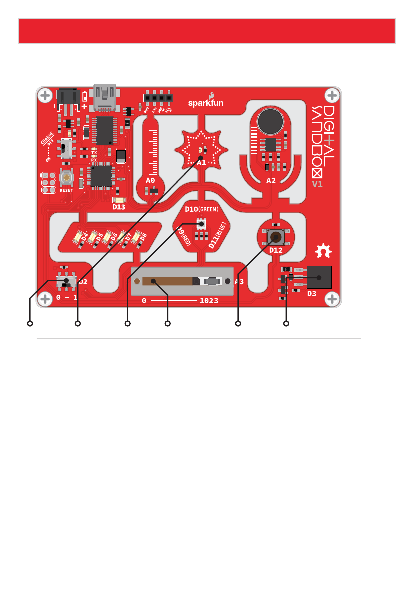
Active Parts
GND
VCC
OUT
Slide Switch Light Sensor RGB LED Slide Potentiometer Push Button Add-on Header
Background Information
By precisely modulating a pin, the Digital Sandbox can create electronic waves which, when
routed through a buzzer, can produce a musical tone. We can program the Sandbox to
control two characteristics of musical tone: pitch and duration.
A tone’s pitch is what we perceive when we think of a note as being very high (screams,
forks scratching plates, etc.) versus very low (like earth-rumbling bass). The pitch of a tone
is very closely related to the frequency played through a buzzer. If we toggle a pin from
HIGH to LOW then LOW to HIGH 440 times per second, for example, it produces a 440 Hz
(hertz) frequency – a “middle A” pitch. Humans can hear frequencies ranging from 20 (lowpitch, bass) to 20,000 Hz (high-pitch, “ow, my ears”).
We can also program the duration of a tone – the length of time a pitch is played. In our
program we’ll use the delay function to set the duration. Playing a tone with the Sandbox is
very easy. Just give it a pitch and it’ll start toggling the output pin for you. Much like analog
output, you can set it and forget it; the tone won’t stop playing until you tell it to.
Page 64
Page 66
Experiment 14: Opto-Theremin (Add-on)
Code Components
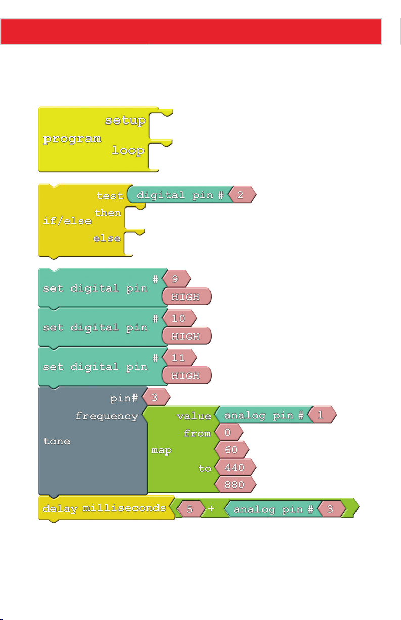
This program introduces the Tone and No Tone block. Here’s the full layout:
Page 65
Page 67
Experiment 14: Opto-Theremin (Add-on)
• Tone: This block takes two inputs: a pin number and a frequency. The pin number
can be any digital pin, but in this case we’ll use the expansion connector on pin 3.
Frequency can be anything from 31 Hz to the extent of your audible range.
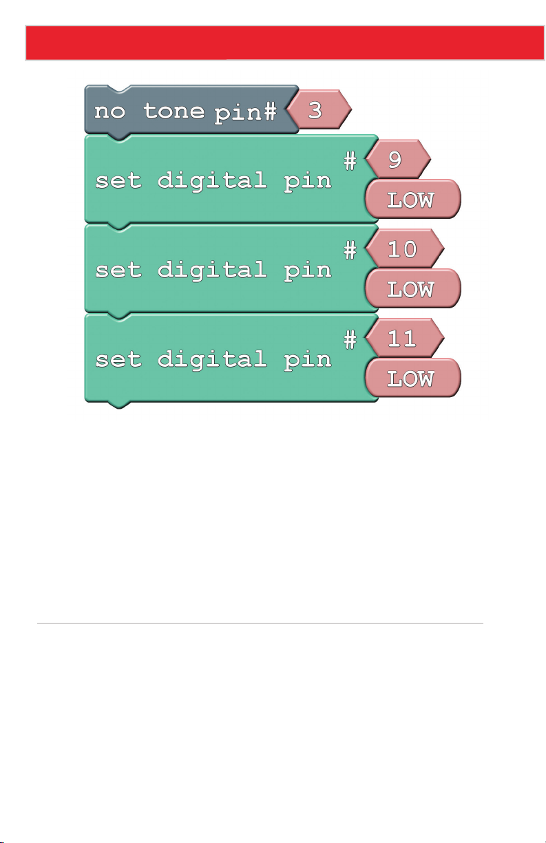
A tone initiated by the Tone block will go on and on until you call a No Tone block. No
Tone simply halts a pin from playing a tone. Both of these blocks can be found under
the Utilities bin.
• Map: This handy function maps a value from one range to another. In this experiment,
we’re taking a value (the output from A3) between 0 and 60, and mapping that to a
range from 440 to 880. So an analog reading of 0 becomes 440, and a reading of 60
becomes 880; anything in between is relative to those two ranges. The map function
can be especially useful in mapping an analog input (0-1023) to an output (0-255).
Do This
There are a lot of blocks in this experiment to snap together! First, snap the If/Else block
in the loop of the Program block. Snap the Set Digital Pin block group in the then of the
If/Else block. Snap the block group that starts with the No Tone block in the else of the
If/Else block.
Page 66
Page 68
Experiment 14: Opto-Theremin (Add-on)
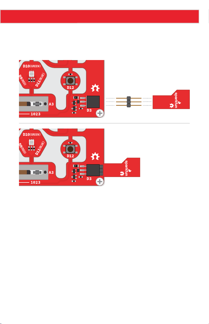
Whew, now upload to the Sandbox! You’ll also need to connect the speaker to the expansion
connector. Before you can do that, you will need to break off one group of three pins from
the male breakaway headers. Now, you can connector the buzzer, with the top side facing
down, to the expansion connector as shown in this image:
RedBot
Buzzer
GND
VCC
OUT
RedBot
Buzzer
GND
VCC
OUT
As fun as the opto-thermin may be, the sound is considered grating by some, so the code
implements a simple ON/OFF function. Slide the switch over to the “1” position to turn the
opto-theremin on.
Once the theremin is on, the speaker should start making noises. Try covering the light
sensor; does the pitch change? We’ve turned the RGB LED white, so you can try to corral
the light from that to control the light sensor.
You can adjust the duration of the tone by sliding the potentiometer. Slide the pot all
the way to 0 to get a really fast, “zapper” sound, or slide to the right to create a soothing,
slow song.
Page 67
Page 69

Experiment 14: Opto-Theremin (Add-on)
Further Explorations
• Try adding a “rest” function to your opto-theremin. Use the push button to
intermittently cut off the sound output.
• Instead of using the Sandbox as a musical instrument, can you program it to play a
written piece of music? Using a series of tones and delays, try reproducing the chorus
of your favorite song!
• Give yourself a hearing test! What’s the highest frequency you can hear? Can you hear
tones others can’t? Can your pet hear pitches that you can’t?
Page 68
Page 70

15: SERIAL MOTORING (ADD-ON)
Motors make the world go round. Well, not literally,
but they make a lot things we use every day spin and
actuate. There are tiny vibration motors in cell phones,
speedy motors that spin CD and Blu-Ray discs, and of
course, massive engine motors that help propel our
cars. In this experiment we’ll explore one of the most
fundamental motor types out there: DC motors. And
we’ll tell the Sandbox precisely how fast we want the
motor to spin.
This experiment is bonus material to be used with the
Digital Sandbox Add-on Kit, which is sold separately.
Page 71
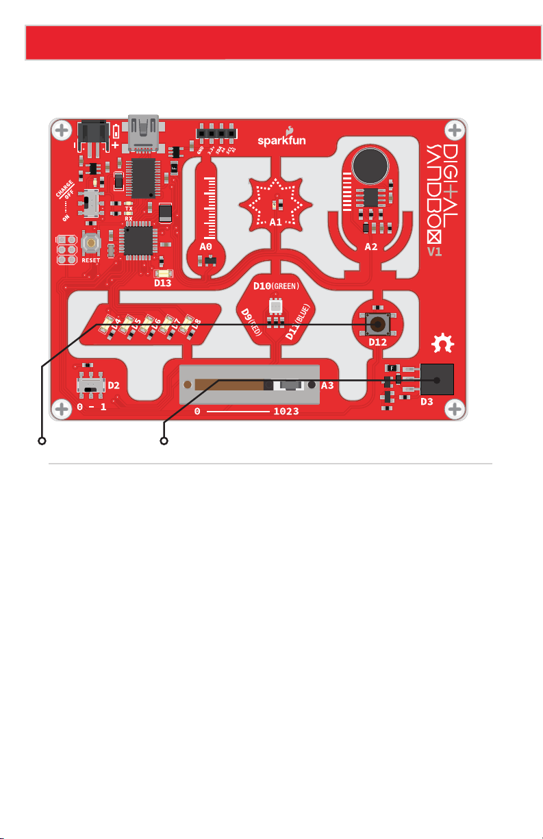
Experiment 15: Serial Motoring (Add-on)
Active Parts
GND
VCC
OUT
Push Button Add-on Header
Background Information
A DC motor turns electrical energy into rotational, mechanical energy. DC motors are
popular because they’re very simple to control – give them some voltage and they spin.
You can control the speed of a motor much as you might control the intensity of an LED –
with PWM – so in this experiment, we’ll be using the analog output block to control the
motor’s speed.
This experiment also introduces serial input. Up to this point our conversations with the
Sandbox have been very one-sided – the Sandbox has been outputting data to the serial
monitor. Serial input allows us to send data to the Sandbox via the serial monitor.
Please note: This experiment has a lot of blocks. Remember you can also open this
experiment from the Digital Sandbox Examples folder, so you can get started faster or
troubleshoot if needed.
Page 70
Page 72
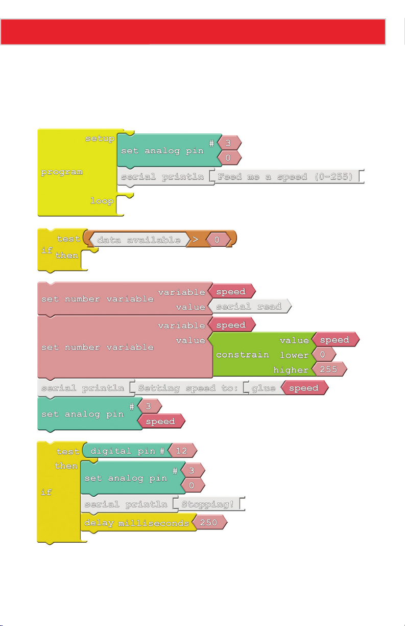
Experiment 15: Serial Motoring (Add-on)
Code Components
Here is the diagram for this program. The Set Analog Pin blocks are used to control the
motor, and a speed variable is used to keep track of the motor speed. A few new blocks
related to serial communication are introduced.
Page 71
Page 73
Experiment 15: Serial Motoring (Add-on)
• Serial Read: We’ll use this block to put serial data into the Sandbox. The Serial Read
block is like a number variable, but instead of using a Set Number Variable block to set
it, we use the Serial Monitor. This block will store the integer most recently sent to the
Sandbox from the Serial Monitor.
• Data Available: This block keeps track of whether or not any serial data is available.
If no serial data has been sent to the Sandbox, this block stores a 0. If data is sent to
the Sandbox this block will return a 1. The value of this block will go back to 0 once the
serial data has been read (using the Serial Read block).
Do This
Snap the Set Number Variable block group into then in the first If block group. Next, snap
the other If block group below the first If block group. You should now have a block group
with two If blocks groups snapped together. Take that big block group and snap into the
loop of the Program block. Now, you can upload the code!
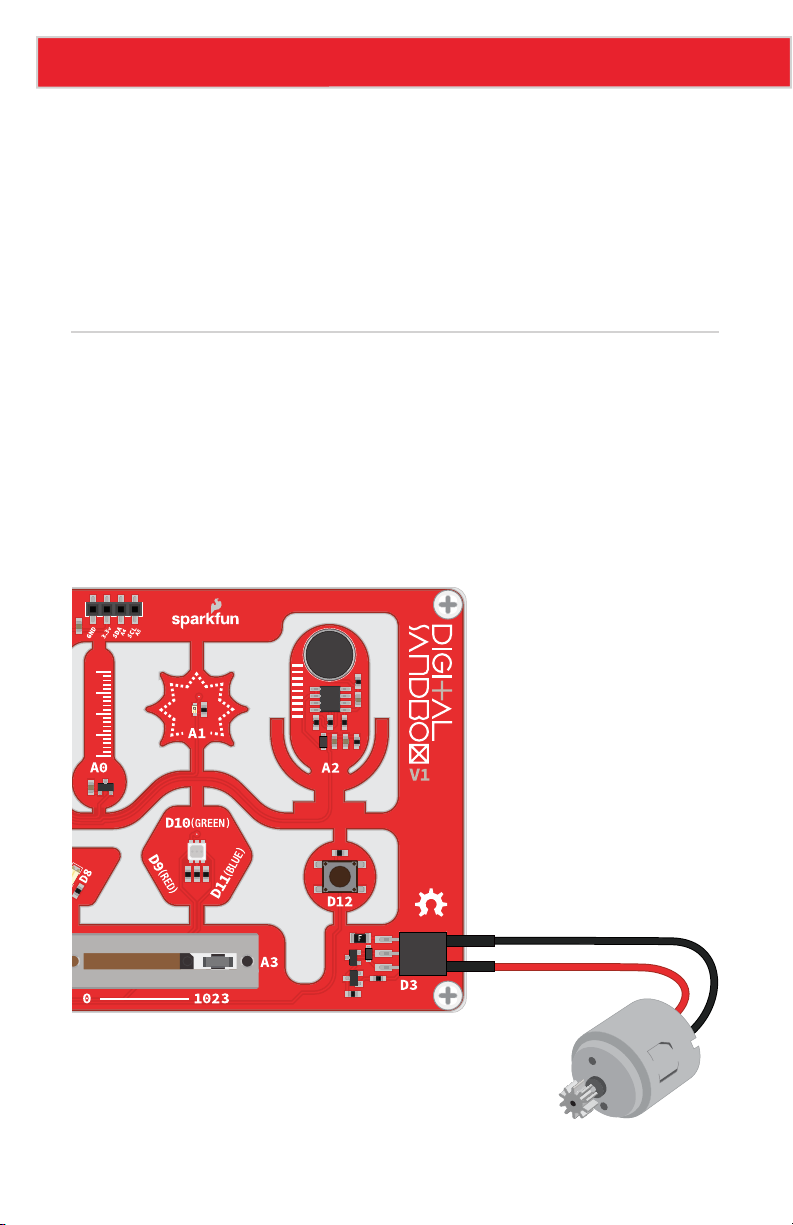
After uploading, connect the motor’s black wire (GND) to the GND pin on the Sandbox’s
add-on header. Then, connect the motor’s red wire to the OUT pin on the Sandbox’s add-on
header. Your motor should now be connected to the Sandbox as shown in this picture:
Page 72
GND
VCC
OUT
Page 74
Experiment 15: Serial Motoring (Add-on)
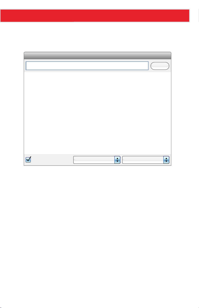
Now open the Serial Monitor, type a number between 0 and 255 into the box next to
“Send,” and then click that button. The Sandbox should respond with a message and the
motor should start spinning.
Send
Feed me a speed (0-255)
Setting speed to:_42
Setting speed to:_84
Setting speed to:_0
Setting speed to:_255
Setting speed to:_172
Setting speed to:_0
Autoscroll
No line ending 9600 baud
What happens when you send 255? How about 0? What happens when you send a number
greater than 255 or less than 0 (a negative)? Can you spot a block in the code that is
restricting those values?
As a “safety mechanism,” if you ever need to stop the motor from spinning, press the button
to bring it to a halt.
Page 73
Page 75

Experiment 15: Serial Motoring (Add-on)
Further Explorations
• Try connecting something mechanical to the motor. Perhaps tape a narrow piece of
paper to create a spinner and play Twister. Or add a few pieces of paper to create a
fan. What else can you connect to the axle to take advantage of the rotational motion?
• As a programming challenge, can you make the motor smoothly speed up or down
when a new serial value is received?
Page 74
Page 76

16: SERVO SWEEPER (ADD-ON)
DC motors are great for spinning an object at high speed
with no regard for where it starts or stops. For many
applications, though, it’s important to precisely control
the position of a motor. Wing flaps in a plane, steering
mechanisms in RC cars, and robotic arm platforms are
applications that benefit from motorized position control.
For those applications we ditch the DC motor and whip
out the servo!
This experiment is bonus material to be used with the
Digital Sandbox Add-on Kit, which is sold separately.
Page 77
Experiment 16: Servo Sweeper (Add-on)
Active Parts
GND
VCC
OUT
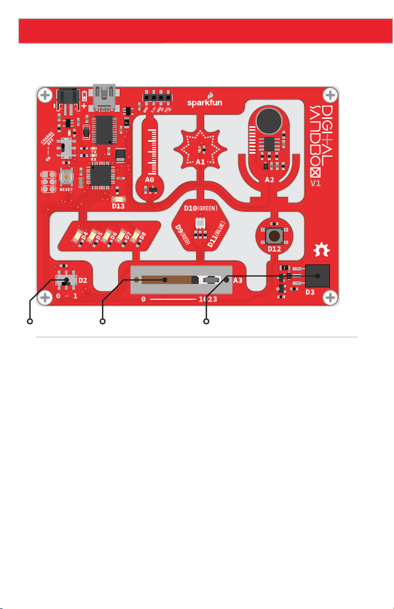
Slide Switch Slide Potentiometer Add-on Header
Background Information
A servo motor is like a DC motor with an internal controller and built-in sensors that help keep
track of its shaft position. A servo motor knows, for example, if it’s pointing at 15° or 115°.
Servos all have three wires that need connecting to: supply voltage, ground, and a signal.
The voltage and ground connections supply the motor with power, and the control signal – a
PWM output (surprise, surprise) – sets the position of the motor. Once the motor reaches the
desired position, it stops until it is commanded to move to a new position.
Servo motors vary in their range of motion – the minimum and maximum angles they can
point to. Only specialized, continuous rotation servos can rotate a full 360°; most have a
stated range of motion between 90° and 180°. The servo we’ll be using in this experiment
has a 180° range of motion.
Page 76
Page 78
Experiment 16: Servo Sweeper (Add-on)
Code Components
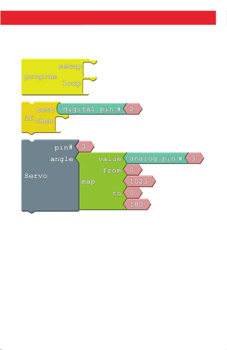
This experiment introduces the Servo block. Here is the layout:
• Servo: This block, found under the Utilities bin, allows you to move a servo to a set
position. There are two inputs to supply to the Servo block: pin number and angle.
Servos can be connected to any pin; we’ll use the multi-purpose pin 3 in this example.
The angle should be a number between 0 and the maximum range of your servo. In
this case we’ll constrain the range between 0 and 180 using the Map block.
Page 77
Page 79
Experiment 16: Servo Sweeper (Add-on)
Do This
Snap the Servo block group into the then of the If block. Next, snap the If block group into
the loop of Program block. Upload it to the Sandbox.
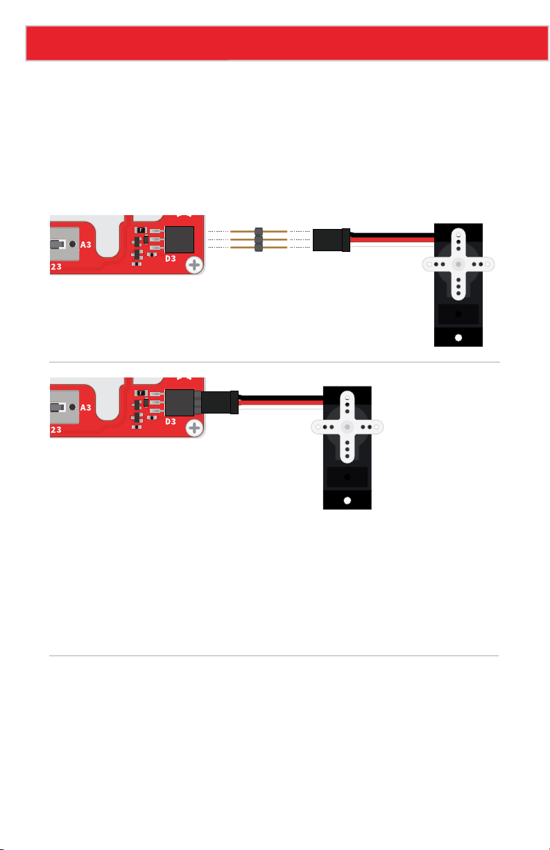
After the code has been uploaded, connect the servo with the three pin male breakaway
header to the Sandbox. Make sure the servo’s black wire (GND) is lined up to the GND pin
on the Sandbox, as shown here:
GND
VCC
OUT
GND
VCC
OUT
This program allows you to control the position of the servo motor with the sliding
potentiometer. Slide all the way to the right to set the servo to 180°, and all the way to the
left to set it to 0°.
The servo will only move if the switch (connected to pin 2) is set to ON. If you leave the
switch in the ON position, you can see how fast the motor responds to the servo block. If
you move the switch to OFF, set the position of the slide pot, and set the switch to ON, you
can see the speed and control mechanisms of the motor.
Further Explorations
• What happens if you try to rotate the servo beyond 180° (change the last value in the
map function)?
• Think of something to attach to the servo! You could add a clock hand to make a weird,
half-circle clock. Or add a papercraft hand, and have your Sandbox give you a high-five!
Page 78
Page 80
Play and Learn!
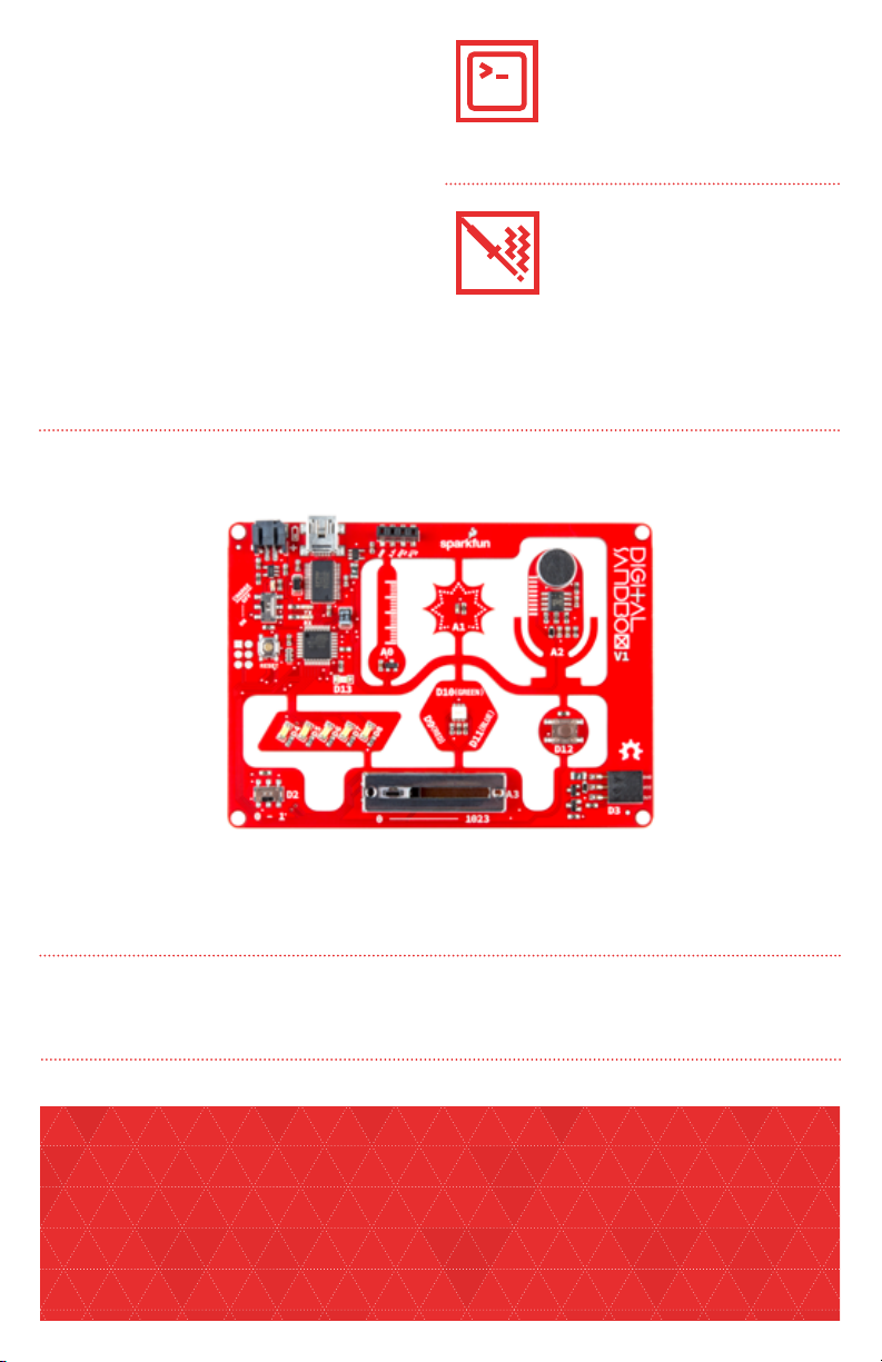
Digital Sandbox helps to introduce
the fundamental concepts of
programming and electronics. Using
ArduBlock – a simple, graphical
version of the popular Arduino
programming language – you
will program 13 experiments that
progressively explore subjects like
digital inputs, analog outputs, serial
communication and more.
DIGITAL SANDBOX
The Digital Sandbox teaches
programming; you will
need a computer and an
internet connection.
No soldering is required.
No previous experience
necessary!
WHAT IS ON THE DIGITAL SANDBOX:
RGB LED
LEDs
Slide potentiometer
WHAT IS INCLUDED IN KIT:
Digital Sandbox board
Instruction manual
THE DIGITAL SANDBOX GUIDE HAS THREE BONUS ADD-ON EXPERIMENTS (ADD-ON PARTS NOT INCLUDED)
© SparkFun Electronics, inc. All rights reserved. The Digital Sandbox Kit features, specifications, system requirements and availability are
subject to change without notice. All other trademarks contained herein are the property of their respective owners.
The Digital Sandbox Guide is licensed under the Creative Commons Attribution Share-Alike 3.0 Unported License
To view a copy of this license visit: http://creativecommons.org/by-sa/3.0/
Or write: Creative Commons, 171 Second Street, Suite 300, San Francisco, CA 94105, USA.
Temperature sensor
Light sensor
Push buttons
Baseplate
Screws
Microphone
Headers
Slide switch
USB connector
ATmega328
Standoffs
USB cable
 Loading...