

Page 1
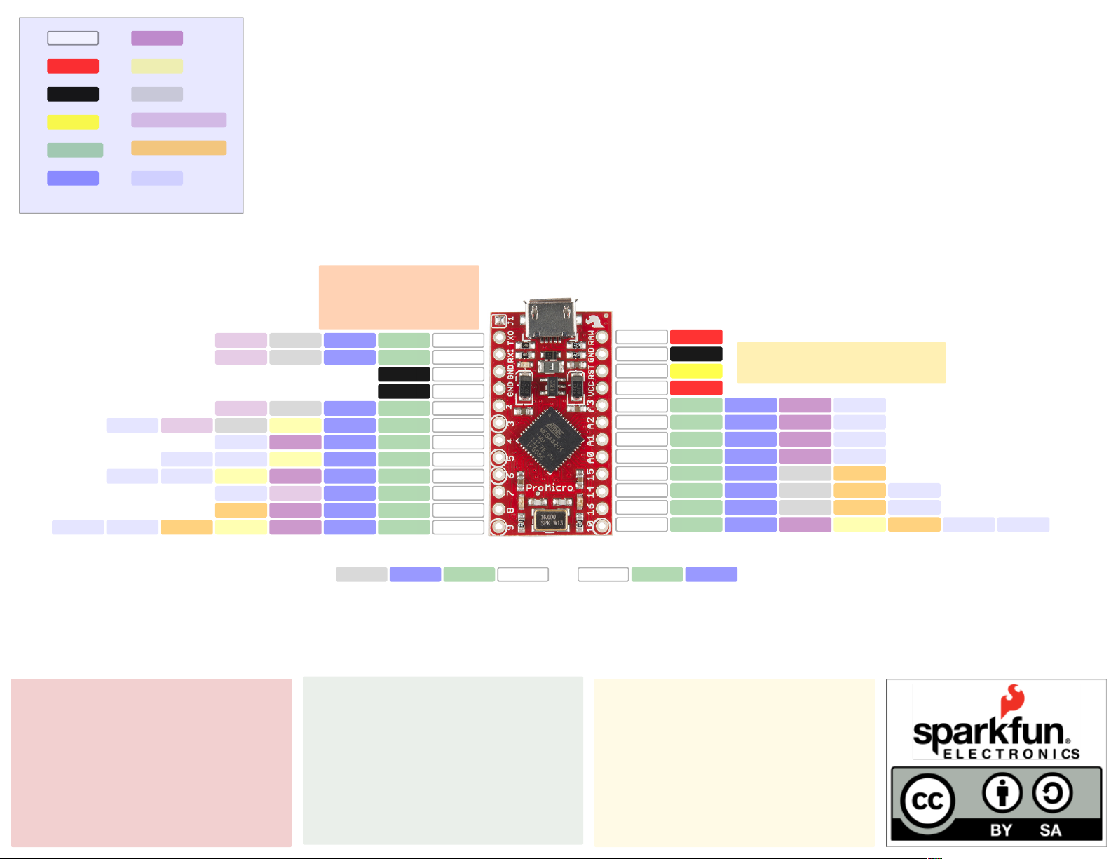
Name
Power
GND
ADC
PWM
Serial
Pro Micro (Dev-12640)
16MHz/5V
Control
Arduino
Port
The Arduino IDE renders all PWM pins as 8-bit
Ext Interrupt
PC Interrupt
Misc
____
____
J1
Connects VCC to USB
(bypasses regulator)
TXOD1PD3TX1INT3
RXID0PD2RX1INT2
GNDGND
GNDGND
2D2PD1SDAINT1
3D3PD08-bitSCLINT0OC0B
4D4/A6PD4ADC8ICP1
5D5PC610-bit (HS)OC3AOCA4
6D6/A7PD7ADC1010-bit (HS)OC4DTO
7D7PE6INT6AIN0
8D8/A8PB4ADC11PCINT4
9D9/A9PB5ADC1216-bitPCINT5OC1AOC4B
MicroB
RAW RAW
GND GND
RST Reset
VCC VCC
A3 A3 PF4 ADC4 TCK
A2 A2 PF5 ADC5 TMS
A1 A1 PF6 ADC6 TDO
A0 A0 PF7 ADC7 TDI
15 D15 PB1 SCK PCINT1
14 D14 PB3 MISO PCINT3 PD0
16 D16 PB2 MOSI PCINT2 PDI
10 D10/A10 PB6 ADC13 16-bit PCINT6 OC1B OC4B
Doubletap the reset 'button' to stay
in bootloader mode for 8 seconds
Power
RAW: 6V-16V
VCC: 5V at 500mA
USB
HID enabled
VID: 0x1B4F
PID: 0x9205 (bootloader); 0x9206 (sketch)
ATmega32U4
Built in USB 2.0
Absolute maxiumum VCC: 6V
Maximum current for chip: 200mA
Maximum current per pin: 40mA
Recommended current per pin:20mA
8-bit Atmel AVR
Flash Program Memory: 32kB
EEPROM: 1kB
Internal SRAM 2.5kB
ADC:10-bit
PWM:8bit
High Speed PWM with programmable
resolution from 2-11 bits
TX_LED D24RX_LEDD17PB0SS
LEDs
Power: Red
RX: Yellow
TX: Green
Serial
Use Serial for the USB connection
Use Serial1 for the hardware serial connection
PD5
 Loading...