

Page 1

SparkFun Electronics
Artemis Module
Integration Guide
Version: 1p0p3
SparkFun Electronics Inc - Artemis Integration Guide - 1p0p3 1
Page 2

Table of Contents
Overview 3
Features 3
Mechanical Specifications 4
Pad Signals and Assignment 7
Designing Artemis Into End Application 10
Programming 10
Reflow Profile and Cleaning 14
Tape and Reel Packaging 14
Regulator Testing and Configuration 16
Regulatory Statements 16
Revision History 18
SparkFun Electronics Inc - Artemis Integration Guide - 1p0p3 2
Page 3

1.Overview
The SparkFun Artemis is a Cortex-M4F based BLE module using the Apollo3 micrcontroller from Ambiq. The
Artemis is capable of running machine learning algorithms with the low current consumption of 6 μA/MHz at
3.3V. The Artemis has an integrated 2.4GHz antenna and incorporates all the necessary circuitry to implement
a low power BLE enabled microcontroller.
2.Features
Ultra-low supply current
- 6μA/MHz executing from flash at 3.3V
- 1μA deep sleep mode (BLE Off) with RTC at 3.3V
- Supply voltage: 1.75V to 3.63V with onboard DC/DC regulation
High-performance ARM Cortex-M4 Processor
- Up to 48 GPIO
- 48 MHz nominal clock frequency, with 96 MHz burst mode
- Floating point unit
- Memory protection unit
- Wake-up interrupt controller with 32 interrupts
- Up to 1 MB of flash memory for code/data
- Up to 384 KB of low leakage RAM for code/data
- 16 kB 2-way Associative/Direct-Mapped Cache
Integrated Bluetooth 5 low-energy module
- RF sensitivity: -93 dBm (typical)
- TX: 3 mA @ 0 dBm, RX: 3 mA
- TX peak output power: 4.0 dBm (max)
Small Size
- 15.5 x 10.5mm including antenna
Easy Integration
- Large SMD pads and spacing allow for low cost 2-layer carrier board implementations
- Programming over pre-configured serial bootloader or JTAG
Ultra-low power ADC
- 14 bit ADC at up to 2.67 MS/s effective continuous, multi-slot sampling rate
- 15 selectable input channels
- Voltage Comparator
SparkFun Electronics Inc - Artemis Integration Guide - 1p0p3 3
Page 4
- Temperature sensor with +/-3ºC accuracy
ISO7816 Secure ‘Smart Card’ interface
Flexible serial peripherals
- 1x 2/4/8-bit SPI master interface
- 6x I2C/SPI masters for peripheral communication
- I2C/SPI slave for host communications
- 2x UART modules with 32-location Tx and Rx FIFOs
- PDM for mono and stereo audio microphone
- 1x I2S slave for PDM audio pass-through
Rich set of clock sources
- 32.768 kHz XTAL oscillator
- Low frequency RC oscillator – 1.024 kHz
- High frequency RC oscillator – 48/96 MHz
- RTC based on Ambiq’s AM08X5/18X5 families
3.Mechanical Specifications
Module Dimensions
15.5 x 10.5 x 2.3mm
Weight
0.6g
Antenna
2.4 - 2.5GHz Chip
SparkFun Electronics Inc - Artemis Integration Guide - 1p0p3 4
Page 5
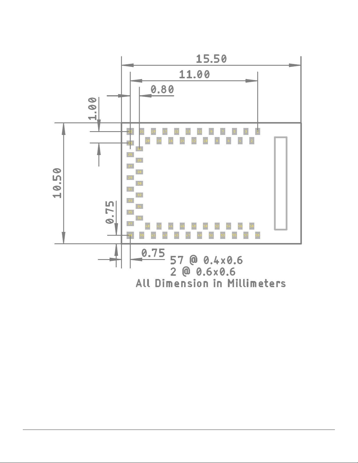
Recommended PCB Layout:
Top View
Copper Pad and Paste Aperture Dimensions
SparkFun Electronics Inc - Artemis Integration Guide - 1p0p3 5
Page 6
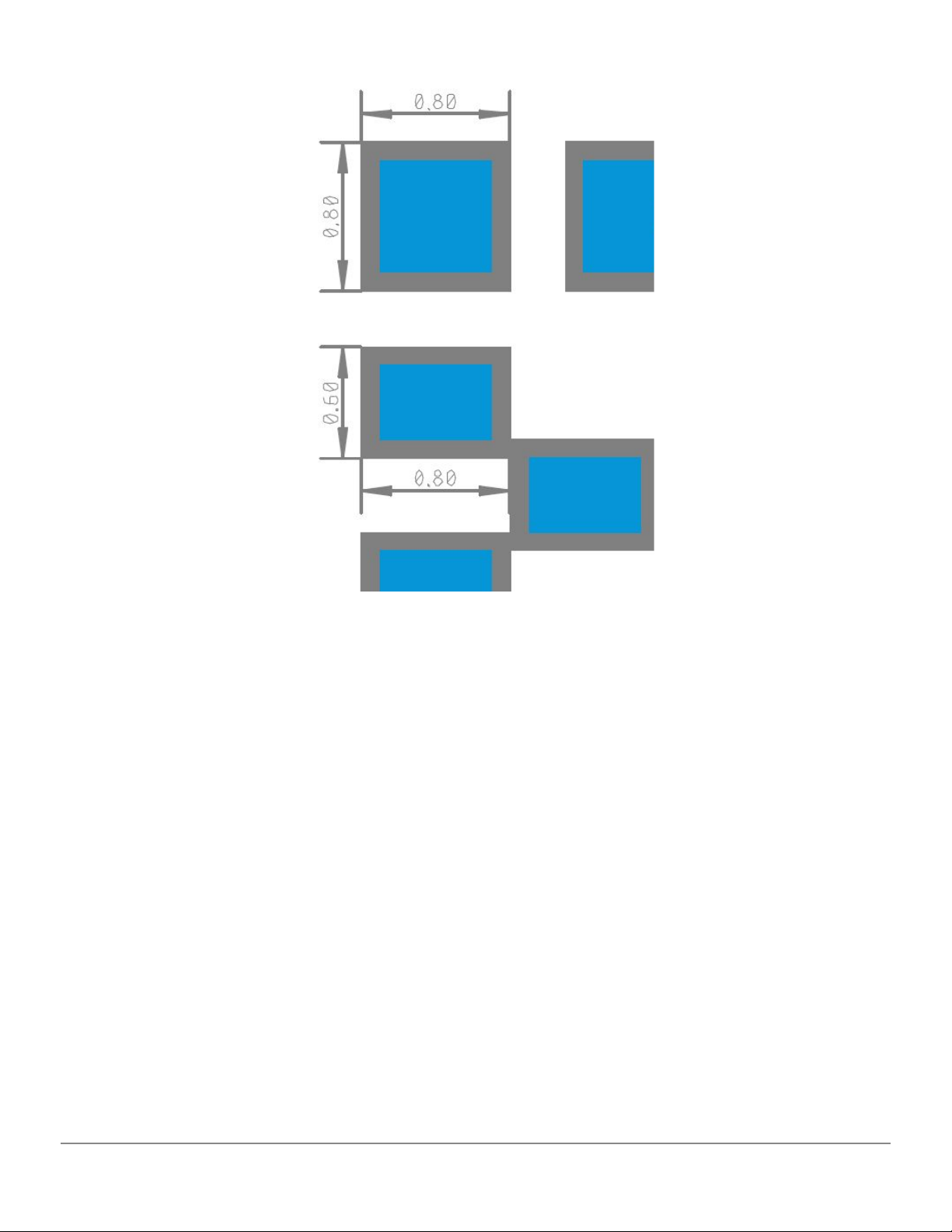
Recommended Soldermask Layout:
Solder Mask Dimensions
SparkFun Electronics Inc - Artemis Integration Guide - 1p0p3 6
Page 7

4.Pad Signals and Assignment
Module
Pad No.
Name
Pin Function
Description
1
GND
Power
Ground
2
GPIO20
SWDCK
JTAG single wire clock
3
GPIO49
RX0 Bootload
RX pin for serial bootloading
4
GPIO39
5
GPIO40
6
GPIO9
7
BOOT
Bootload
Hold pin high during reset to initiate bootloader
8
GPIO10
9
GPIO48
TX0 Bootload
TX pin for serial bootloading
10
GPIO21
SWDIO
JTAG single wire I/O
11
GPIO8
12
GPIO5
13
GPIO7
14
GPIO35
All GPIOs have up to 8 possible functions ranging from I2C,
15
GPIO4
SPI, PDM, SCC, UART, I2S, and clock sources. Please
16
GPIO24
see the Apollo3 datasheet for a complete listing of capabilities.
17
GPIO22
18
GPIO23
19
GPIO27
20
GPIO14
21
GPIO28
22
GND
Power
23
GPIO6
24
GPIO32
25
GPIO25
26
GPIO12
27
GPIO26
28
GPIO13
29
GPIO15
30
GPIO33
31
GPIO34
32
GPIO11
33
GPIO29
SparkFun Electronics Inc - Artemis Integration Guide - 1p0p3 7
Page 8

34
XO
32kHz Xtal
Connection for external 32.768kHz RTC crystal
35
XI
32kHz Xtal
Connection for external 32.768kHz RTC crystal
36
VDD
Power
37
VDD
Power
38
GND
Power
39
GND
Power
40
GPIO19
41
GPIO18
42
GPIO16
43
GPIO17
44
GPIO31
45
GPIO41
46
GPIO45
47
GND
Power
48
GPIO2
49
GPIO1
50
nRESET
System Reset
Pull pin low to reset system
51
GPIO0
52
GPIO43
53
GPIO42
54
GPIO3
55
GPIO36
56
GPIO38
57
GPIO37
58
GPIO44
59
GND
Power
SparkFun Electronics Inc - Artemis Integration Guide - 1p0p3 8
Page 9
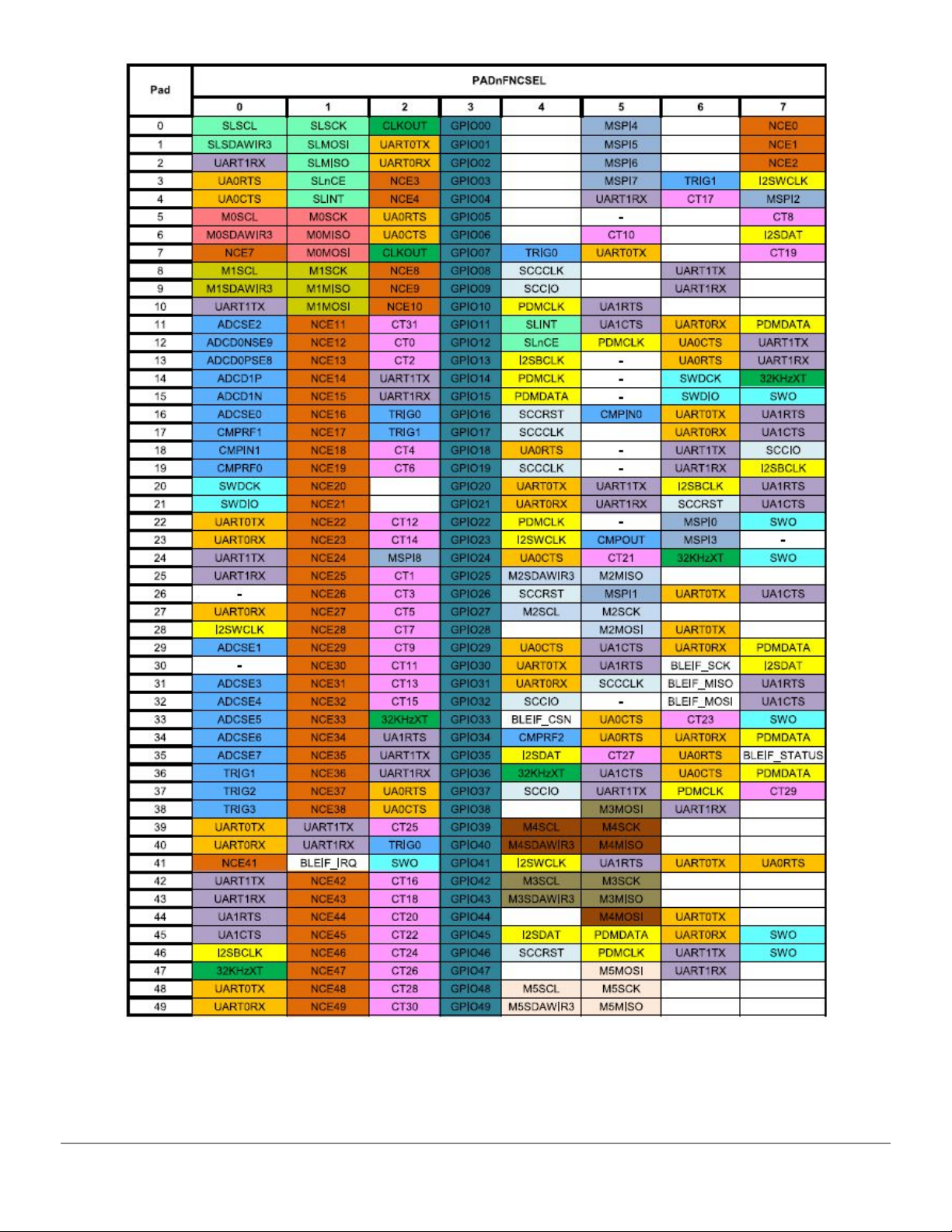
Overview of Pad Functions
Note: Apollo Pad# maps to GPIO# on Artemis
SparkFun Electronics Inc - Artemis Integration Guide - 1p0p3 9
Page 10
5.Designing Artemis Into End Application
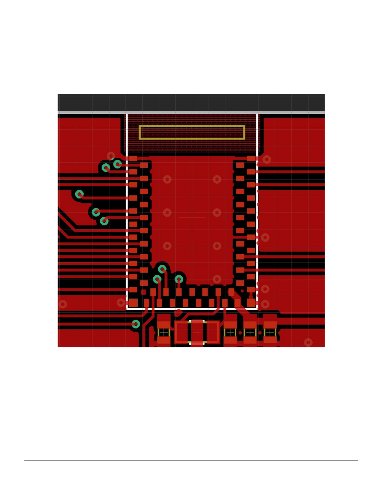
Routing and Recommended Keep Out
An example layout with ground pour and ground vias
The Artemis module was designed to be implemented onto low cost 2-layer PCBs with easy 8mil trace/space
routing. A good ground connection is essential. Routing under the module is allowed. Keep all ground pours
away from the antenna area. If mechanical exposure allows for it the antenna can be extended over the edge
of the PCB for increased reception.
6.Programming
SparkFun Electronics Inc - Artemis Integration Guide - 1p0p3 10
Page 11
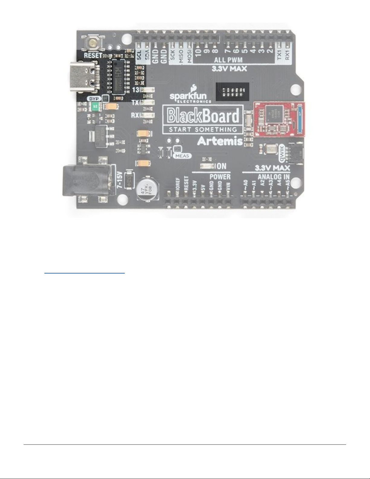
Two example programming interfaces
Artemis can be programmed using the standard JTAG interface or with a serial bootloader. The Artemis
module can be routed to USB to serial circuit or an industry standard JTAG connector for more advanced
programming and debugging. For more information on ARM programming, including JTAG interfaces, check
out our ARM Programming Tutorial.
SparkFun Bootloader
We've designed a baud rate flexible bootloader that is run at each power on reset. What does baud rate
flexible mean exactly? The computer initiates communication at a given baud rate (921600bps for example)
and the Artemis auto-detects the baud rate and transfers the bulk of the binary data at the agreed upon rate.
This enables upload speeds up to 921600bps; significantly reducing upload times. A flexible rate allows
computer systems that may have problems at higher rates to select the rate that works best. This bootloader is
the preferred method for uploading sketches and user code that needs quick and reliable means of getting new
code onto the Artemis.
SparkFun Electronics Inc - Artemis Integration Guide - 1p0p3 11
Page 12
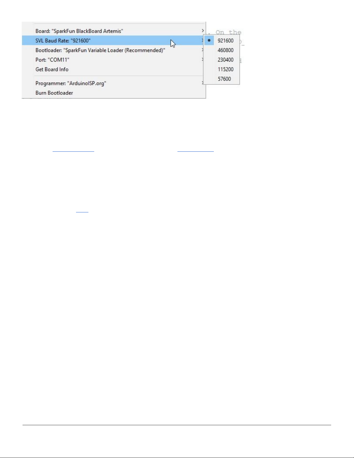
Once you've selected an Artemis target board additional menu options will appear the next time you open the
Tools menu. The SVL Baud Rate options will allow you to change the upload speed. 921600bps is the
recommended speed as it's extremely fast to update new sketches. However, there are some platforms (Linux
flavors) where the standard CH340 USB to serial drivers don't operate well at speeds higher than 115200. So if
you run into upload problems, consider reducing the upload speed. For more information about Linux upload
issues see this forum post and consider upgrading with these drivers.
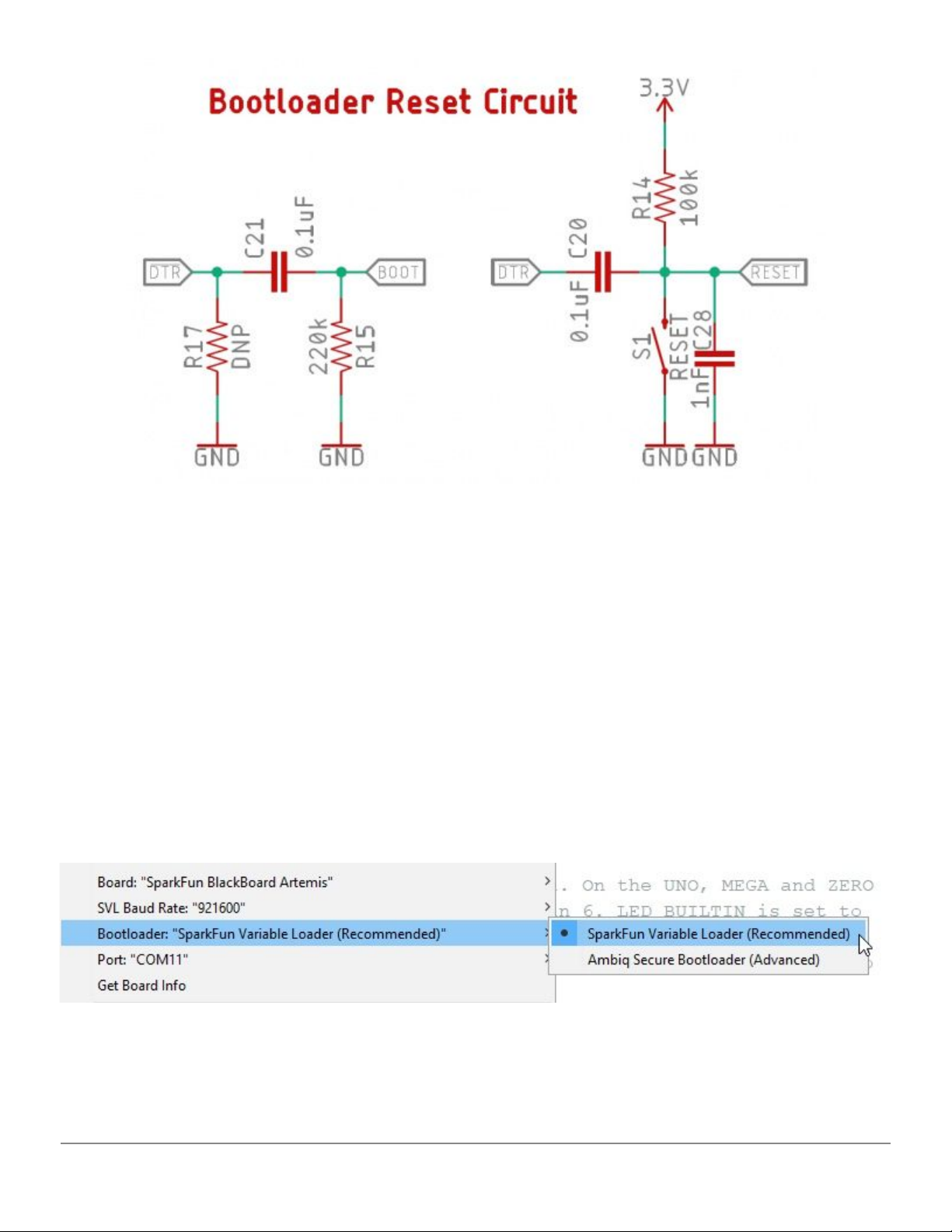
Just like the classic Arduino Uno, Arduino Mega, etc, the bootloader is activated by resetting the board. A
single 0.1uF capacitor between DTR and reset is all that is needed to cause the Artemis to reset and enter
bootload mode. If no new firmware is detected within a short amount of time (50ms), user code is run.
If you're into niche electrical engineering discussions on things like bootloaders, you can read more about the
Artemis bootloader here.
Factory Bootloader
In addition to the SparkFun Artemis bootloader, we program every Artemis with the Ambiq factory Secure
Bootloader (SBL). This bootloader is best used for low-level updates to devices that need to have a secure
provenance. The bootloader is activated at reset if pin 47 is high and communicates at 115200. The bootloader
will then wait indefinitely for new binary data. SparkFun provides a python tool as well as an executable to
communicate with this bootloader.
SparkFun Electronics Inc - Artemis Integration Guide - 1p0p3 12
Page 13
This style of bootloading is slightly different from bootloaders that you may be accustomed to. The STK500
bootloader that runs on most ATmega328 based Arduinos is run automatically at reset, then times out and the
user’s code is run. The Artemis bootloader is similar but requires an extra pin (the Bootload pin) to be held
high. To make using Artemis as cheap and easy as possible we’ve designed a simple RC circuit that can be
implemented on your design using USB-to-serial ICs with the bare minimum control pins (the CH340E has only
RTS) and still allow for factory bootloader activation. If you suspect you will need to modify the SparkFun
Artemis Bootloader (described above) or if you need to use the secure bootload toolchain, the circuit above
can be used to bootload using a single pin (DTR or RTS is supported). This single-pin reset and bootload
solution is ideal for any USB to serial implementation that has control pins exposed (CH340, CP210x, FT232,
etc).
Heads up! You will never damage or brick the Artemis but using the Ambiq Secure Bootloader tools will overwrite
the SparkFun bootloader removing the faster upload abilities. We don't recommend using the Ambiq Secure
Bootloader for general Arduino programming.
Don't select Ambiq Secure Bootloader unless you know what you're doing
To load new code onto your Artemis module using the Ambiq bootloader toolchain select the Ambiq Secure
Bootloader option in the Arduino Tools->Bootloader menu. These tools will modify your binary and package
SparkFun Electronics Inc - Artemis Integration Guide - 1p0p3 13
Page 14

them with various security headers. The code will load at 115200bps and may fail. Hit upload again if the
process fails.
How the Single Pin RC Circuit Works
By pulling DTR (or RTS) low, the module is reset. After 10ms, DTR is pushed high in software. This causes the
bootload pin to be high for 100ms allowing the bootloader to run. Opening of a serial port causes DTR to go
low causing the module to reset, but because DTR stays low during normal serial operations the module does
not enter the SBL and instead proceeds to run the SparkFun Artemis Bootloader.
We have modified the Ambiq python bootload tool so that both DTR and RTS are driven at the same time, and
in the same way, so you can use either RTS or DTR to bootload the Artemis. Our Ambiq SBL tools then drive
DTR/RTS high to enter the the factory bootloader.
If you prefer, the bootload pin can be broken out to a button. When the user holds the button and resets the
board the Artemis will enter bootload mode and stay there until a bootload cycle completes or a reset occurs.
This method works well but requires the user’s interaction every time new code needs to be loaded.
7.Reflow Profile and Cleaning
Cleaning
The use of “No Clean” paste is recommended as it does not require a wash phase after reflow. Washing a final
assembly that uses the Artemis is not recommended as water may be captured under the module and/or RF
shield causing part degradation.
Recommended Reflow Profile
The Artemis module follows standard reflow handling and processing. Please refer to the Jedec
J-STD-020-D.1 reflow profile. Multiple reflow exposures are not recommended.
8.Tape and Reel Packaging
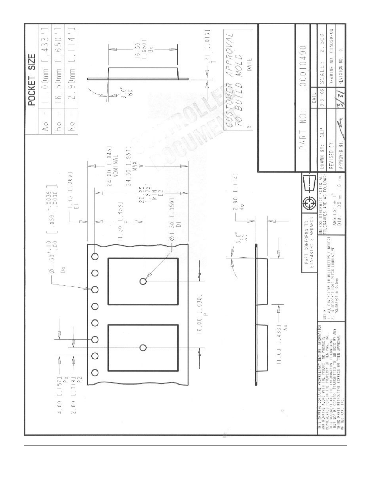
Artemis comes on 24mm reels of 500pcs with 16mm pocket spacing as shown below.
SparkFun Electronics Inc - Artemis Integration Guide - 1p0p3 14
Page 15
SparkFun Electronics Inc - Artemis Integration Guide - 1p0p3 15
Page 16

9.Regulator Testing and Configuration
If necessary the Artemis module can be configured for host product evaluation for different operational
conditions. In other words, if Artemis is implemented into a host system that needs secondary certifications the
Artemis can be loaded with test firmware to put the radio into different constant transmission or reception
states to verify the end device does not emit spurious emissions caused by the Artemis. The test firmware and
documentation for implementation is located in the Ambiq SDK under ‘uart_ble_bridge’.
10. Regulatory Statements
FCC Statements
FCC Statements
This device complies with part 15 of the FCC Rules. Operation is subject to the following two conditions:
1) This device may not cause harmful interference, and
2) This device must accept any interference received, including interference that may cause undesired
operation.
Cet appareil est conforme à la section 15 des réglementations de la FCC. Le fonctionnement de l’appareil est
sujetaux deux conditions suivantes :
1) cet appareil ne doit pas provoquer d’interférences néfastes, et
2) cet appareil doit tolérer les interférences reçues, y compris celles qui risquent de provoquer un
fonctionnement indésirable.
Note: This product has been tested and found to comply with the limits for a Class B digital device, pursuant to
part 15 of the FCC Rules. These limits are designed to provide reasonable protection against harmful
interference in a residential installation. This product generates, uses, and can radiate radio frequency energy
and, if not installed and used in accordance with the instructions, may cause harmful interference to radio
communications. However, there is no guarantee that interference will not occur in a particular installation. If
this product does cause harmful interference to radio or television reception, which can be determined by
turning the equipment off and on, the user is encouraged to try to correct the interference by one or more of the
following measures:
- Reorient or relocate the receiving antenna.
- Increase the separation between the equipment and receiver.
- Connect the equipment into an outlet on a circuit different from that to which the receiver is connected.
- Consult the dealer or an experienced radio/TV technician for help.
Warning: Changes or modifications to this unit not expressly approved by the party responsible for compliance
could void the user's authority to operate the equipment.
FCC Radiation Exposure Statement
This equipment complies with FCC radiation exposure limits set forth for an uncontrolled environment. End
users must follow the specific operating instructions for satisfying RF exposure compliance.
SparkFun Electronics Inc - Artemis Integration Guide - 1p0p3 16
Page 17

FCC Modular Usage Statement
Note 1: This module certified complies with RF exposure requirements under mobile or fixed condition; this
module is to be installed only in mobile or fixed applications.
A mobile device is defined as a transmitting device designed to be used in other than fixed locations and to
generally be used in such a way that a separation distance of at least 20 centimeters is normally maintained
between the transmitter's radiating structure(s) and the body of the user or nearby persons. Transmitting
devices designed to be used by consumers or workers that can be easily re-located, such as wireless devices
associated with a personal computer, are considered to be mobile devices if they meet the 20 centimeter
separation requirement.
A fixed device is defined as a device is physically secured at one location and is not able to be easily moved to
another location.
Note 2: Host product manufacturers must provide in their user manual the required RF exposure information
for mobile & fixed usage of this module. Host product manufacturers must use the following RF exposure
statement in their user manual “This equipment complies with FCC radiation exposure limits set forth for an
uncontrolled environment. This equipment should be installed and operated with a minimum distance of 20 cm
between the radiator and all persons. This transmitter must not be co-location or operating in conjunction with
any other antenna or transmitter.”
Note 3: Any modifications made to the module will void the Grant of Certification, this module is limited to OEM
installation only and must not be sold to end-users, end-user shall have no manual instructions to remove or
install the device, only software or operating procedure shall be placed in the end-user operating manual of
final products.
Note 4: Additional testing and certification may be necessary when multiple modules are used.
Note 5: The module may be operated only with the integral chip antenna with which it is authorized.
Note 6: To ensure compliance with all non-transmitter functions the host manufacturer is responsible for
ensuring compliance with the module(s) installed and fully operational. For example, if a host was previously
authorized as an unintentional radiator under the Supplier’s Declaration of Conformity procedure without a
transmitter certified module and a module is added, the host manufacturer is responsible for ensuring that the
after the module is installed and operational the host continues to be compliant with the part 15B unintentional
radiator requirements. Since this may depend on the details of how the module is integrated with the host, the
manufacturer shall provide guidance to the host manufacturer for compliance with the part 15B requirements.
Note 7: The FCC ID label on the final system must be labeled with “Contains FCC ID: 2ASW8- ART3MIS” or
“Contains transmitter module FCC ID: 2ASW8- ART3MIS”.
Note 8: The FCC rule/s for this module are CFR 47 Part 15 Subpart C.
Note 9: This modular transmitter is only FCC authorized for the specific rule parts listed on its grant. The host
product manufacturer is responsible to any other FCC rules that apply to the host not covered by the modular
SparkFun Electronics Inc - Artemis Integration Guide - 1p0p3 17
Page 18

transmitter grant of certification. The final host product will require Part 15 Subpart B compliance when the
modular transmitter is installed.
ISED Statements
This device complies with Innovation, Science and Economic Development Canada’s license-exempt RSS
standard(s). Operation is subject to the following two conditions:
1) this device may not cause interference, and
2) this device must accept any interference, including interference that may cause undesired operation
of the device.
Le présent appareil est conforme aux CNR d’Innovation, Sciences et Développement Èconomique Canada
applicables aux appareils radioexempts de licence. L'exploitation est autorisée aux deux conditions suivantes :
1) l'appareil ne doit pas produire de brouillage, et
2) l'utilisateur de l'appareil doit accepter tout brouillage radioélectrique subi, même si le brouillage est
susceptible d'en compromettre le fonctionnement.
Under Innovation, Science and Economic Development Canada’s regulations, this radio transmitter may only
operate using the integral antenna under which it was approved.
Conformément à la réglementation d’Innovation, Sciences et Développement Èconomique Canada, le présent
émetteur radio peut fonctionner avec une antenne fonctionner qu’en utilisant l’antenne intégrée sous laquelle il
a été approuvé.
ISED RF Exposure Statement
This equipment complies with ISED radiation exposure limits set forth for an uncontrolled environment. This
equipment should be installed and operated with minimum distance 20cm between the radiator & your body.
This transmitter must not be co-located or operating in conjunction with any other antenna or transmitter.
Le rayonnement de la classe b repecte ISED fixaient un environnement non contrôlés.Installation et mise en
œuvre de ce matériel devrait avec échangeur distance minimale entre 20 cm ton corps.Lanceurs ou ne
peuvent pas coexister cette antenne ou capteurs avec d’autres.
ISED Modular Usage Statement
NOTE 1: When the ISED certification number is not visible when the module is installed inside another device,
then the outside of the device into which the module is installed must also display a label referring to the
enclosed module. This exterior label can use the wording ”Contains transmitter module IC: 25186-ART3MIS”
or “Contains IC: 25186-ART3MIS”.
NOTE 1: Lorsque le numéro de certification ISED n'est pas visible lorsque le module est installé dans un autre
appareil, l'extérieur de l'appareil dans lequel le module est installé doit également afficher une étiquette faisant
référence au module inclus. Cette étiquette extérieure peut être libellée Contient le module émetteur IC:
25186-ART3MIS ou Contient IC: 25186-ART3MIS.
SparkFun Electronics Inc - Artemis Integration Guide - 1p0p3 18
Page 19

11. Revision History
Revision
Date
Description
1p0p0
June-2-2019
Initial Release
1p0p1
July-23-2019
Add Regulatory Statements
Add Programming
Move recommended layout to new
section
1p0p2
August-9-2019
Update regulator information. Add
regulatory testing section. Add
reflow information. Add tape and
reel diagram.
1p0p3
August-12-2019
Updated regulator information.
SparkFun Electronics Inc - Artemis Integration Guide - 1p0p3 19
 Loading...