

Page 1

SPARKER DC-CDIP 2 RACE
SPARKER DC-CDI-P2 RACE is a conductive ignition unit for road motorcycles. The ignition unit can be programmed via a
computer and it is fully tunable as regards ignition timing. It contains an ignition advance curve/map depending on engine
revolutions and throttle position. It also contains peripheries such as: tachometer output, four multifunction "power outputs",
outputs and input for servo-exhaust-chokes, three multifunction inputs and a configurable input for a correction potentiometer.
During programming, the ignition unit is connected to a computer via a serial port. A setup application " DCCDIP2race.EXE"
is included with the ignition unit. Connection is provided via a waterproof connector JAE MX23A 26-NF1.
HARDWARE
Sensing system.
The ignition unit has two channels and it can be used with almost all sensing systems. Selected sensing systems are set up
directly from a drop-down list in the "DCCDIP2race.EXE" application. Other sensing systems can be set up using a special
procedure in the DCCDIP2race.EXE application.
Supply voltage B+12 V input.
Supply voltage must be within the range from 8 to 18 V. Within this range, the ignition unit is able to optimally control all
processes. The ignition unit will be switched off if voltage decreases below 8 V or exceeds 18 V. Supply voltage is connected
with the positive pole to outlet no. 7 and with the negative pole to outlets no. 15 and 16.
Throttle position sensor (TPS) input.
The input is designed for standard throttle position sensors used in motorcycles. It can accept voltages from 0 to 5 V. Sensor
settings for 0 % and 100 % are included in the "DCCDIP2race.EXE" application.
TPS is supplied with reference voltage + 5 V (outlet no. 20) and sensing ground (outlet no. 23). Sensor output is connected to
outlet no. 6.
Crankshaft position sensor (CKPS) inputs.
Inputs are prepared for standard pick-up sensors (coil-magnet) used in motorcycles as CKPS. One outlet of the CKPS is
connected to the connector (outlet no. 13) and the second outlet is connected to sensing ground (outlet no. 23). In case of a
two-sensor sensing system, one outlet of the second sensor is connected to the connector (outlet no. 26) and the second outlet is
connected to sensing ground (outlet no. 23).
Multifunction input 1.
One outlet of the sensor is connected to the connector (outlet no. 25) and the second outlet is connected to ground. If you
activate the switch, a function selected by the "DCCDIP2race.EXE" application will be executed.
Multifunction input 2.
One outlet of the switch or sensor is connected to the connector (outlet no. 24) and the second outlet is connected to ground. If
you activate the switch, a function selected by the "DCCDIP2race.EXE" application will be executed. If "Speed gear" is
selected, a variable resistor (which senses the position of the engaged speed gear) will be connected to this input.
Multifunction input 3.
One outlet of the sensor is connected to the connector (outlet no. 22) and the second outlet is connected to ground. If you
activate the switch, a function selected by the "DCCDIP2race.EXE" application will be executed. If "Speed" is selected, the
output of an impulse speed sensor (must be of the "hall" type) will be connected to this outlet.
POTENTIOMETER input.
The correction potentiometer wiper will be connected to this input (outlet no. 12); its front will be connected to sensing ground
(outlet no. 23) and its end to reference voltage + 5 V REF (outlet no. 20) . Use the "DCCDIP2race.EXE" application to select
which value will be corrected by the potentiometer.
Outputs for induction coils IC 1, IC 2.
One outlet of induction coil IC 1 will be connected to the connector (outlet no. 14) and the second outlet will be connected to
ground! One outlet of induction coil IC 2 will be connected to outlet no. 1 and the second outlet will be connected to ground!
Warning!!! If you connect the second end of the induction coil to +12 V instead of the ground, the ignition unit will be
destroyed.
Tachometer output.
The tachometer output is compatible with most dashboard instruments used on motorcycles. The number of pulses per one
revolution is set in the "DCCDIP2race.EXE" application.
The tachometer is supplied with +12 V against GND. The tachometer input is connected to the connector (outlet no. 19).
Page 2

"Power output" 1.
This is a multifunction output (open-type collector) which can be set via the "DCCDIP2race.EXE" application to execute one
of pre-defined functions. It is outlet no. 2 in the connector. The instrument is connected with one end to outlet no. 2 and with
the second end to + 12 V.
Power output 1 is predefined (default) as a fuel pump relay switch.
"Power output" 2.
This is a multifunction output (open-type collector) which can be set via the "DCCDIP2race.EXE" application to execute one
of pre-defined functions. It is outlet no. 3 in the connector. The instrument is connected with one end to outlet no. 3 and with
the second end to + 12 V.
Power output 2 is predefined (default) as a gear-shift pilot light switch.
"Power output" 3.
This is a multifunction output (open-type collector) which can be set via the "DCCDIP2race.EXE" application to execute one
of pre-defined functions. It is outlet no. 5 in the connector. The instrument is connected with one end to outlet no. 5 and with
the second end to + 12 V.
Power output 3 is predefined (default) as a "POWERJET" electromagnetic valve switch.
"Power output" 4.
This is a multifunction output (open-type collector) which can be set via the "DCCDIP2race.EXE" application to execute one
of pre-defined functions. It is outlet no. 11 in the connector. The instrument is connected with one end to outlet no. 11 and with
the second end to + 12 V.
Power output 4 is predefined (default) as a general use switch.
Outputs and input for SERVO.
Outputs and input for servo are compatible with most brush servomotors used on motorcycles.
The servo motor is connected to outlets no. 4 and 17. The wiper of the servo's sensing potentiometer is connected to outlet no.
8. The servo's potentiometer is supplied with reference voltage + 5 V (outlet no. 20) and sensing ground (outlet no. 23).
DCCDIP2 race - color, position wires.
color in cable
adapter
white 1 IC 2 ignition coil 2
violet 2 POWER OUT 1 Power out 1 (fuel pump relay)
blue/white 3 POWER OUT 2 Power out 2 (gear shift light)
green 4 MOTOR+ EXUP output for servomotor
pink 5 POWER OUT 3 Power out 3 (POWER JET Honda)
grey 6 TPS throttle position sensor input
red 7 SUPPLY +12V supply +12 V
white/blue 8 STPS servomotor position sensor input
black 9 RS232 (pin 2 in 9pin connector)
yellow 10 RS232 (pin 3 in 9pin connector)
violet/black 11 POWER OUT 4 Power out 4
white/black 12 POT correction potentiometer
yellow 13 PICK-UP 1 pickup 1
orange 14 IC 1 ignition coil 1
blue 15 GND power ground
blue 16 GND ground for RS232 (pin 5 in 9pin connector)
green 17 MOTOR- EXUP output for servomotor
orange 18 RS232 connector (pin 9 in 9pin connector)
green/yellow 19 TACHO OUT tachometer output
white/red 20 V REF +5 V supply +5V for sensors
violet 21 RS232 connector (pin 1 in 9pin connector)
grey/black 22 INPUT 3 multifunction input 3
light blue 23 SENSE GND ground for sensors
black 24 INPUT 2 multifunction input 2
grey/red 25 INPUT 1 multifunction input 1
brown 26 PICK-UP 2 pickup 2
pin no. in
connector
name description
Page 3
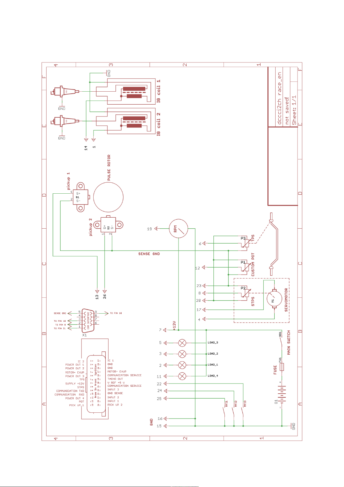
DCCDIP2 race - recommended wiring.
3
Page 4

"DCCDIP2race.EXE" application
4
Drop-down menus
File - items: New - default data setting
Open - opens a data file
Open from EXE dir - opens a data file from the location where the program
is installed
Save - saves a data file
Save to EXE dir - saves a data file to the location where the program is
installed Print - prints the current setting
of the current tab
Print all - prints the current settings all tabs
Exit - exits the program
New - sets default values for all parameters
These correspond approx. to a four-cycle engine without
a TPS.
Port - contains items Com1 to Com auto - selection
communication lines, manually or automatically
For PCs which only have a USB port, it is necessary to
use the adapter USB/RS232.
Ignition - items: Read F7 - reads data from the unit
Verify F8 - compares data in the PC and in the unit
Program F9 - sends data to the unit and verifies it
Tools - items: Minus F4 - hot key for adding on the active tab
Plus F5 - hot key for subtracting on the active tab
Language - contains language setting items: English, German,
French and Czech
Help - items: Help - opens the Assembly instructions (this file)
About the program - information about the program (version, date)
Icon menus
- sets default values
Warning!!! Click this icon to automatically set all parameters to their default values.
- opens a data file
- saves a data file
- prints the current setting
- step back
- step forward
Page 5

- see the Device drop-down menu
5
Motorcycle tab
Motorcycle type - selection of a sensing system for a specific motorcycle
Number of revolutions without ignition - sets the number of revolutions at which there will be no ignition
Opposite polarity of sensor 1 - allows the setting of opposite polarity (first negative) on sensor 1
Opposite polarity of sensor 2 - allows the setting of opposite polarity (first negative) on sensor 2
Synchronization description * - method of synchronization (consult with the manufacturer)
- channel 1 - assignment of an ignition position for the first channel
- channel 2 - assignment of an ignition position for the second
channel
- setting of the number of ignitions per one revolution
Correction - percentual correction of the tachometer output value
Number of pulses per one revolution - rough setting of the tachometer output
Reading ban - if this field is activated and saved in ignition, it will not be possible
to read the data saved in ignition
* The settings in this menu are only active if a "special" type motorcycle is selected.
Inputs tab
Functions are assigned to multifunction inputs on this tab.
Input 1 may have the following functions *
- Off: The input has no function.
- Kill switch: If the input is activated, ignition is not performed.
- Blocking: If the input is not activated, ignition is not performed.
- Clutch master: After activation, an operation is performed in ignition according to the "Race" tab.
- Ignition advance reduction: After activation, the ignition advance decreases – see the column next.
- Starting limiter: After activation, revolution limiters are reconfigured according to the "Limiter" column
on this tab.
- 2nd ignition advance map: After activation, ignition advance will be activated according to the
"Ignition Advance 2" map.
Input 2 may have the following functions *
- Off: The input has no function.
- Kill switch: If the input is activated, ignition is not performed.
- Blocking: If the input is not activated, ignition is not performed.
- Clutch master: After activation, an operation is performed in ignition according to the "Race" tab.
- Ignition advance reduction: After activation, the ignition advance decreases – see the column next.
- Starting limiter: After activation, revolution limiters are reconfigured according to the "Limiter" column
on this tab.
- 2nd ignition advance map: After activation, ignition advance will be activated according to the
"Ignition Advance 2" map.
- Speed gear: With this selection, the input measures voltage at a resistor sensor of the engaged speed
gear; this selection will be performed automatically if "Voltage" is selected in the "Speed gear
determination" column on the "Gear" tab. The setup of individual values for speed gears is performed on
the "Gear" tab.
Input 3 may have the following functions *
- Off: The input has no function.
- Kill switch: If the input is activated, ignition is not performed.
- Blocking: If the input is not activated, ignition is not performed.
Page 6

- Clutch master: After activation, an operation is performed in ignition according to the "Race" tab.
6
- Ignition advance reduction: After activation, the ignition advance decreases – see the column next.
- Starting limiter: After activation, revolution limiters are reconfigured according to the "Limiter" column
on this tab.
- 2nd ignition advance map: After activation, ignition advance will be activated according to the
"Ignition Advance 2" map.
- Speed: With this selection, it measures frequency or period of pulses taken to this input and recalculates
it to speed according to the setting on the "Gear" tab in the "Speedometer setting" column. This selection
will be performed automatically if "Rpm and speed ratio" is selected in the "Speed gear determination"
column on the "Gear" tab.
The setup of individual values for speed gears is performed on the "Gear" tab.
Activation by switching * - When this field is checked, the logic of activation of the respective input is
reversed. If this field is not checked, the selected function is activated by grounding
of the input. If the field is checked, the selected function is activated by
disconnection from the ground.
TPS - Here, absolute limits of the throttle position sensor (TPS) are set.
Using the button TPS -> 0%, it is possible to insert a value for the zero throttle.
Using the button TPS -> 100%, it is possible to insert for a fully open throttle.
Values can also be inserted manually. After determining the limit values, it is necessary to store these
values in the ignition by pushing the "program" button, otherwise they will not be
executed.
Advance reduction - Ignition advance reduction: Specifies the number of angle degrees by which
ignition advance will be reduced if one of the multifunction inputs is selected (it
must be set as "Ignition advance").
- Number of clutch master switchings after retard switch-off:
1. If a "0" is set, the ignition advance is reduced only for the period of activation of the respective
"Ignition advance reduction" multifunction input.
2. If a number higher that zero is set, ignition advance is reduced even after the activation of the
respective "Ignition advance reduction" multifunction input is ended, until the
number of "clutch master" activations corresponding to the number in the "
Number of clutch master switchings after retard switch-off" field is executed.
Limiter - Soft starting limiter: Value of revolutions, from which one of three ignitions is left
out, if it is activated by one of the "Starting limiter" function multifunction inputs.
- Starting limiter: Value of revolutions, from which ignition is switched off, if it is activated by one of the
"Starting limiter" function multifunction inputs.
- Starting limiter of switch-on retarder: Time interval between input activation and the beginning of the
"Starting limiter" function execution.
- Soft limiter: Value of revolutions, from which one of three ignitions is left out.
- Limiter: Value of revolutions, from which ignition is switched off.
Switching to the 2nd advance map
- Acceleration threshold: Value of engine acceleration (by how many revolutions per second) at which the
map is switched to "Ignition advance 2". If this function is not desirable, it is
necessary to set a high acceleration value which cannot be reached (20,000).
Potentiometer - Changes: This is used to select which value will be corrected by the correction
voltage input (correction potentiometer):
1) Off - No operation is executed.
2) Ignition advance - The potentiometer can be used to correct ignition advance
by +/- the value set in the "range" cell (at the bottom).
3) Starting limiter - The potentiometer can be used to correct revolution values
for starting limiters by +/- the value set in the "range" cell (at the bottom).
4) Gear-shift pilot light - The potentiometer can be used to correct revolution
values, from which the gear-shift pilot light will light up by +/- the value set in
the "range" cell (at the bottom).
Page 7

5) Switching to the second map - The potentiometer can be used to correct
BASE
ADVANCE
7
acceleration threshold by +/- the value set in the "range" cell.
Ignition advance map tab - Ignition advance 1
Ignition advance map 1
This is the base (1st) ignition advance map. It is used when the 2nd ignition advance map function is not
activated from some multifunction input, or when the preset motor acceleration ("Acceleration threshold") is not
exceeded.
The ignition advance map contains 150 adjustable points depending on revolutions and on throttle position. It is
possible to collectively set whole columns using arrows under the columns. Collective setting of the whole
ignition advance curve can be done using the collective change tool (+ and - buttons with the "All" selection).
When the motor is running, the current segment in the ignition advance curve/map is highlighted (in green).
When the collective change tool (+ and - buttons without the "All" selection) is used, only the current segment
will be changed. Individual channels can be corrected with a value in the "correction" cells.
Throttle position sensor (TPS) - selection of ignition advance map/curve
Base advance - Base ignition advance definition – see the image:
.... i.e. you must enter such an ignition advance value in the "base ignition advance" field which equals to
the "base advance" angle (base advance – see the image). The image depicts the top dead centre of the
given cylinder. It is recommended to check whether the current advance corresponds with the setting
made using the stroboscope lamp.
Ignition advance map tab - Ignition advance 2
Ignition advance map 2
This is the alternative (2nd) ignition advance map. It is used when the 2nd ignition advance map function is
activated from some multifunction input, or when the preset motor acceleration ("Acceleration threshold") is
exceeded.
The ignition advance map contains 150 adjustable points depending on revolutions and on throttle position. It is
possible to collectively set whole columns using arrows under the columns. Collective setting of the whole
ignition advance curve can be done using the collective change tool (+ and - buttons with the "All" selection).
When the motor is running, the current segment in the ignition advance curve/map is highlighted (in green).
When the collective change tool (+ and - buttons without the "All" selection) is used, only the current segment
will be changed. Individual channels can be corrected with a value in the "correction" cells.
Throttle position sensor (TPS) - selection of ignition advance map/curve
Base advance - Is shared with the Ignition advance 1 tab
Servo tab
Page 8

Contains 15 x 10 adjustable points of revolutions [RPM]/required voltage of position sensor or percentage of
8
opening [mV or %].
Servo allowed - software activation of servo controller
Percentage - The activation of this function will rearrange the map (curve) into the percentage mode, i.e. we
do not enter requirements in terms of voltage but in terms of servo opening. In this case it is
necessary for the system to have mechanically delimited end positions, from which voltage values
for 0% and 100% are read after switch-on. Or – after the servo is switched on, the motor runs only
for approx. 5 seconds in one direction until it reaches a mechanical stopper, where the unit reads
the voltage value and records it as 0%, and then the servo is reversed until it reaches the second
mechanical stopper, where the respective voltage value is read again and recorded as 100 %. If
mechanical stoppers are not found, the system is evaluated as "faulty" and the engine is shut down
until the next switching on. In the monitor, the "Measured servo" and "Required servo" fields are
highlighted in red as system faults. If the "Percentage" selection is not active, the servo controller
rotates the servomotor to the required voltage according to the map (curve). In this case, after the
unit is switched on with the movement of the servomotor, it is necessary to find the lowest and the
highest voltage value in the map (curve). If these values are not found after switch-on, the system
is evaluated as "faulty" and the engine is shut down until the next switching on. In the monitor, the
"Measured servo" and "Required servo" fields are highlighted in red as system faults. Both modes
support auto-detection of the engine's movement direction.
Servodrive requirement sources
R+T In this case, the whole map is used: RPM (revolutions) versus TPS (throttle position)
RPM In this case, only one line is used (revolutions curve).
T In this case, only one column is used. The drive copies the movement of TPS according to proportions in
the column.
Hysteresis - This is the limit (+/- in mV) from which the servomotor's output starts to decrease proportionally.
In case that the drive vibrates, it is necessary to increase this value.
These buttons allow us to increase or decrease the value of the voltage requirement (or the percentage
requirement) in the active field, and the keys F4 and F5 have the same function. Moreover, if the
function "All" is activated, then values in the whole map (curve) are increased or decreased. If we
want to change these values on-line, for example when the engine is running, and if we want the
changes to become effective immediately, it is necessary to activate the "Program after change"
function (bottom right).
Power output tab (two tabs, four equivalent power outputs)
Power output mode xx
1) Off The power output will not be activated by anything.
2) Fuel pump The power output will be activated if RPM is higher than 0 RPM.
3) Pilot light The power output will be activated if RPM is higher than the preset "RPM" value.
4) Power Jet HondaThe power output will be active a) up to 5% TPS from 4,500 RPM
(5% and 4,500 RPM can be changed)
b) over 5% TPS from 12,500 RPM
(5% and 12,500 RPM can be changed)
5) Special The power output will be active according to the truth table; two TPS levels; three RPM
levels.
Hysteresis This is a range of insensitivity to a change in revolutions [RPM] , which must be exceeded
in order to return the output to the previous condition.
Gear-shift tab
Speed gear determination - Defines the method of determining an engaged speed gear.
Voltage - Determination according to voltage measured on "Input 2". A
rheostate (resistance) monitor is used as the sensor (mostly it is a part
Page 9

of the gearbox) and its highest resistance should not exceed 20 kOhm.
9
The activation of this selection automatically sets the selection for
"Input 2" as "Speed gear" on the "Inputs" tab. Gear ratios are entered
manually by inserting values in the "Speed-gear setting" fields or by
shifting to the given gear and clicking the respective button "Gear 06". The values must be saved in the unit using the "Program" button or
using the active "Program after change" selection.
RPM/speed ratio - Determination using a calculation of the RPM/speed ratio with
manual input. The activation of this selection automatically sets the
selection for "Input 3" as "Speed" on the "Inputs" tab. It is necessary
to use a HALL-type sensor with an open collector or a reed contact;
the sensor must "ground" the input. Gear ratios are entered manually
by inserting values in the "RPM/Speed" fields or during engine run by
shifting to the given gear and clicking the respective button "Gear 06". The values must be saved in the unit using the "Program" button or
using the active "Program after change" selection.
Automatic RPM/speed ratio - Determination using a calculation of the RPM/speed ratio with
automatic search. The activation of this selection automatically sets
the selection for "Input 3" as "Speed" on the "Inputs" tab. It is
necessary to use a HALL-type sensor with an open collector or a reed
contact; the sensor must "ground" the input. In order to guarantee the
correct operation of this function, it is necessary to fill in the
"Automatically from the RPM/Speed ratio" column.
It contains: Min time [s] - This is the minimum time for the
stabilization of the RPM/Speed ratio which is
necessary for the overwriting of the ratio for the
given speed gear.
Min RPM [RPM] - This is the RPM value which
the engine must reach for the overwriting of the ratio
for the given speed gear.
Min TPS [%] - This is the minimum angle for the
opening of the throttle which is necessary for the
overwriting of the ratio for the given speed gear.
Range [%] This is the percentage value of the
deviation in tenths of the gear ratio, under which the
respective gear ratio is determined.
Number of speed gears Here it is necessary to enter the number of the motorcycle's
speed gears (except the neutral gear).
Speedometer setting
Number of pulses - Number of pulses per 1 second for 100 km/h (suitable for a
higher number of pulses – for example for the sensor in the gearbox).
Distance - Distance between individual pulses in millimetres of distance
covered (suitable for a small number of pulses – for example one per a
wheel revolution).
Race tab
Clutch mode - Setting of the clutch master mode. The clutch master can be set in such a
way that either ignitions are blocked for the period during which the clutch
master is in operation, or the advance is set to "Clutch advance".
Clutch master - Setting of common parameters for the clutch master.
Clutch master pause 1 - This is the time of retardation between the input pulse and the beginning of
the drawing-out of the clutch master (switches off ignition or shifts the
ignition advance). It is used in cases when a sensor of the position of the
gear-shift lever is used.
Clutch master pause 2 - This is the protective period during which no other requirements are
accepted from the clutch master sensor. This prevents the undesirable
switching-on of the clutch master, e.g. when the gear-shift lever returns.
Page 10

Min RPM for clutch - This is the value of the number of revolutions per minute, under which the
1
"Clutch master" function is not executed.
Clutch master advance - This is the value of advance which will be implemented when the "Clutch
advance" mode is selected.
According to speed gear * - Clutch master time: Here are the values of times [ms] for individual speed
gears.
Correction according to speed gear * - Advance: Here are the +/- corrections of ignition advance for
individual speed gears.
- Limiter: Here are the +/- corrections of the revolutions of limiters for individual speed gears.
- Servo: Here is the value of revolutions which is added or subtracted from actual revolutions, and the
result is used to make a selection from the map (or curve) of the
servodrive.
- Pout1-4: Here are the +/- values of revolutions for individual speed gears which are added or subtracted
from actual revolutions, and the result is then used as a value for the
switching of power outputs 1 to 4.
* These settings work correctly only on the condition that "Speed gear determination" is set up
correctly.
Tests tab
Here you can find buttons to test individual outputs. Using these buttons you can test all the power outputs in the
controller.
No connection with PC: The unit is not connected or it is not switched on or the COM port has not been
selected correctly.
Monitor tab
- Here it is possible to see the sensor values and the engine's motor operational characteristics. There are
messages in the top right corner:
ADVANCE - The field displays the current advance information.
ADVANCE 1 - Ignition advance angle calculated from the map for channel 1 [°].
ADVANCE 2 - Ignition advance angle calculated from the map for channel 2 [°].
MAX Advance 1 - Maximum attainable ignition advance for channel 1.
MAX Advance 2 - Maximum attainable ignition advance for channel 2.
Starting limiter activated - Notification of the activation of the starting limiter.
Soft starting limiter - Notification of the activation of the soft starting limiter.
Starting limiter - Notification of the activation of the starting limiter.
Soft limiter - Notification of the activation of the soft limiter.
Limiter - Notification of the activation of the limiter (leaving out all ignitions).
Throttle position (TP) - throttle position [mV]
Potentiometer - Voltage value of the correction potentiometer [mV]
Ignition advance reduction - Notification of the activation of the ignition advance reduction function.
Clutch master - Notification of the activation of the clutch master function.
2nd advance map - Notification of the activation of the 2nd advance map function.
Acceleration - Display of the current value of engine acceleration.
Input grounded - This field displays the situation of multifunction inputs.
Input1 - Notification of grounding of Input 1.
Input2 - Notification of grounding of Input 2.
Input3 - Notification of grounding of Input 3.
Power outputs - This field displays the condition of power outputs.
First line - Condition of power input 1
Second line - Condition of power input 2
Third line - Condition of power input 3
Fourth line - Condition of power input 4
Page 11

Change from potentiometer
1
- This field displays the corrections of individual values derived from the voltage of the correction
potentiometer.
- The advance displays the possible advance correction.
- The starting limiter displays the possible correction of the starting limiter.
- The gear-shift pilot light displays the possible correction of the gear-shift pilot light.
- The acceleration threshold displays the possible correction of the acceleration threshold.
COM - Displays the current communication channel.
Common monitor - The always-visible values are displayed here.
RPM - The current value of "revolutions per minute".
TP - The current value of "throttle opening".
Advance - The current value of "ignition advance" which is currently being executed.
U - The current value of "controller supply voltage".
Blocking - The result of the blocking function.
Speed - The current value of the vehicle's speed (it must be correctly defined on the "Gear" tab).
Speed gear - Display of the currently engaged speed gear ("Gear" tab).
Crankshaft sensor 1 - Shows whether pulses are being received via the "pickup 1" input.
Crankshaft sensor 2 - Shows whether pulses are being received via the "pickup 2" input.
Measured servo - The current value of "servodrive sensor voltage".
Required servo - The current value of "calculated voltage requirement for servodrive".
Programming after change - Activation of the "programming after change" function. If it is selected, any
changes in the software application will be immediately saved in the unit.
 Loading...