

Page 1

Slim 46 VF
Slim 26 VF
MODELS: VF-26NG, VF-26LP, VF-46NG, VF-46LP
SPARK FIRE RIBBON
VENT FREE
GAS FIREPLACES
Report #0361GF005S
Page 2

TABLE OF CONTENTS
Important Safety Information 2
Room Volume for Vent Free 4
Specifications 6
Assembly & Installation 10
Lighting & Operation 19
Maintenance 27
Maintenance Log 28
Replacement Parts List 29
Control Schematic 30
Installation Record 31
Warranty Information 32
Page 3

IMPORTANT SAFETY INFORMATION
WARNING:
- Any change to this heater or its controls can be dangerous.
- Improper installation or use of the heater can cause serious injury or death from fire, burns,
explosion or carbon monoxide poisoning.
- Do not allow fans to blow directly into the fireplace. Avoid any drafts that alter burner flame
patterns.
- Do not use a blower insert, heat exchanger insert or other accessory, not approved for use with
this heater.
1. Due to high temperatures, the heater should be located out of traffic and away from furniture
and draperies.
2. Children and adults should be alerted to the hazard of high surface temperature and should
stay away to avoid burns or clothing ignition.
3. Young children should be carefully supervised when they are in the same room with the heater.
4. Do not place clothing or other flammable material on or near the heater.
5. Any safety screen or guard removed for servicing an appliance, must be replaced prior to
operating the heater.
6. Installation and repair should be done by a qualified service person. The heater should be
inspected before use and at least annually by a professional service person. More frequent
cleaning may be required due to extensive lint from carpeting, bedding material, etc. It is
imperative that control compartments, burners and circulating air passageways of the heater be
kept clean.
7. To prevent malfunction and/or sooting, an unvented gas heater should be cleaned before use
and at least annually by a professional service person.
8. CARBON MONOXIDE POISONING: Early signs of carbon monoxide poisoning are similar to the
flu with headaches, dizziness and/or nausea. If you have these signs, obtain fresh air
immediately. Have the heater serviced as it may not be operating properly.
9. The installation must conform with local codes or, in the absence of local codes, with the
National Fuel Gas Code, ANSI Z223.l/NFPA54.
10. This unit was tested and listed to ANSI Z21.11.2-2013 by OMNI-Test Laboratories.
11. This appliance is approved for installation in the Commonwealth of Massachusetts. The Board of
State Examiners of Plumbers and Gas Fitters has approved these appliances.
12. Do not install this heater in a bathroom or bedroom.
2
Page 4

IMPORTANT SAFETY INFORMATION
13. Correct installation of the fire media, proper location of the heater, and annual cleaning are
necessary to avoid potential problems with sooting. Sooting, resulting from improper
installation or operation, can settle on surfaces outside the fireplace. See media placement
instructions for proper installation.
14. WARNING: Avoid any drafts that alter burner flame patterns. Do not allow fans to blow directly
into fireplace. Do not place a blower inside burn area of firebox. Ceiling fans may create drafts
that alter burner flame patterns. Sooting and improper burning will occur.
15. Caution: Candles, incense, oil lamps, etc. produce combustion by-products including soot. Vent
Free heaters will not filter or clean soot produced by these types of products. In addition, the
smoke and/or aromatics (scents) may be reburned in the vent free heater which can produce
odors. It is recommended to minimize the use of candles, incense, etc. while the vent free heater
is in operation.
16. Keep room area clear and free from combustible materials, gasoline and other flammable
vapors and liquids.
17. This appliance is intended for supplemental heating.
18. Unvented gas heaters emit moisture into the living area. In most homes of average
construction, this does not pose a problem. In houses of extremely tight construction,
additional mechanical ventilation is recommended.
19.
During manufacturing, fabricating and shipping, various components of this heater are treated
with certain oils, films or bonding agents. These chemicals are not harmful but may produce
annoying
smoke and smells as they are burned off during the initial operation of the heater;
possibly causing headaches or eye or lung irritation. This is a normal and temporary
occurrence. The initial break-in
operation should last four to six hours with the burner at the
highest setting. Provide maximum ventilation by opening windows or doors to allow odors to
dissipate. The amount of time required for the initial break-in is dependent on a number of
variables determined by your specific installation including but not limited to surfaces and
surface finishes adjacent to the fireplace which may off gas for some period of time. Any odors
remaining after this initial break-in period will be slight and will disappear with continued use.
20. Input ratings are shown in BTU per hour and are for elevations up to 2,000 feet. If your
installation is at an elevation greater than these, consult with the local authority having
jurisdiction for gas product installations to determine their specific requirements for high
altitude installations.
21.
The heater must be isolated from the gas supply piping system by closing its equipment shutoff
valve during any pressure testing of the gas supply piping system at test pressures equal to or
less
than
1/2
psi (3.5 kPa).
22. Do not use this room heater if any part has been under water. Immediately call a qualified
service technician to inspect the heater and to replace any part of the control system and any
gas control which has been under water.
23. Never burn solid fuels in a fireplace where an unvented heater is installed.
24. WARNING: Any change to this heater or its controls can be dangerous.
3
Page 5

ROOM VOLUME FOR VENT FREE
CODES
ADEQUATE COMBUSTION AND VENTILATION AIR
Adhere to all local codes or, in their absence, the latest edition of THE NATIONAL FUEL GAS CODE ANSI
Z223.1 or NFPA54 which can be obtained from…
American National Standards Institute, Inc.
This heater shall not be installed in a confined space or unusually tight construction unless provisions
are provided for adequate combustion and ventilation air.
The National Fuel Gas Code, (ANSI Z223.1/NFPA 54), defines a confined space as a space whose volume is
less than 50 cubic feet per 1,000 BTU per hour (4.8 m
appliances installed in that space. An unconfined space is defined as a space whose volume is not less
than 50 cubic feet per 1,000 BTU per hour (4.8 m3 per kw) of the aggregate input rating of all appliances
installed in that space. Rooms communicating directly with the space in which the appliances are
installed, through openings not furnished with doors, are considered a part of the unconfined space.
1430 Broadway New York, NY 10018
or National Fire Protection Association, Inc.
Batterymarch Park Quincy, MA 02269
3
per kw) of the aggregate input rating of all
UNUSUALLY TIGHT CONSTRUCTION IS DEFINED AS CONSTRUCTION WHERE…
• walls and ceilings exposed to the outside atmosphere have a continuous water vapor retarder
with a rating of 1 perm (6 x 10¹¹ kg per pa-sec-m2) or less with openings gasketed or sealed;
• weather stripping has been added on operable windows and doors, and
• caulking or sealants are applied to areas such as joints around window and door frames,
between sole plates and floors, between wall-ceiling joints, between wall panels, at penetrations
for plumbing, electrical, and gas lines, and at other openings.
WARNING:
This heater shall not be installed in a room or space unless the required volume of indoor
combustion air is provided by the method described in the National Fuel Gas Code, ANSI Z223.1/NFPA
54, the International Fuel Gas Code, or applicable local codes.
This is an unvented gas-fired heater, it uses air (oxygen) from the room in which it is installed.
Provisions for adequate combustion and ventilation air must be provided.
4
Page 6

ROOM VOLUME FOR VENT FREE
The following formula can be used to determine the maximum heater rating (per the definition of
unconfined space) that is allowed in your space:
()
.=
Example A: Consider a room with the following dimensions: L=16ft, W=14ft, H=8ft
(16)
(14) (8)
50
Example B: Consider a room with the following dimensions: L1=16ft, W1=14ft, H1=8 which is
communicating directly with the space in a second room through openings not furnished with doors
having the following dimensions: L2=14ft, W2=12ft, H2=8
() ()
1000
50
1000 = 35,840 .
.=
1000
50
(1) (1) (1) + (2) (2) (2)
With data input into the equation:
(16) (14) (8) + (14) (12) (8)
1000 = 62,720 .
50
Will my space support a SPARK Fire Ribbon Vent Free Gas Fireplace?
Maximum BTU/Hr. my space will support (use formula above) a) _______________
BTU/hr. of SPARK Fire Ribbon Vent Free Gas Fireplace b) _______________
If the answer to a) is greater than b) then your space will support the installation of a SPARK Fire
Ribbon Vent Free Gas Fireplace; if a) is less than b) then your space will not support a SPARK Fire
Ribbon Vent Free Gas Fireplace.
Bringing in Outside (or “Make-up”) Air:
Many building code jurisdictions require that outside or “make-up” air be provided when installing a
fireplace of this type. This requirement can be satisfied by the proper installation of an ‘outside air
kit’ which is not provided. The final determination of the suitability of any particular kit must be
made by the installer.
If an outside air supply is desired it should be added to the room in which the SPARK Fire Ribbon Vent
Free Gas Fireplace is installed, not to the chase enclosing the fireplace.
If outside air is introduced into the chase, competing air pressures could compromise the operation
of the fireplace.
5
Page 7

SPECIFICATIONS
NATURAL GAS SPECIFICATION CHART
PROPANE (LP) SPECIFICATION CHART
INPUT Slim 26 VF Slim 46 VF
Input Rating BTU/Hr. 26,000 37,000
Min. Input BTU/Hr. 16,000 23,000
Orifice Size - DMS #46 #38
GAS SUPPLY Slim 26 VF Slim 46 VF
Manifold Pressure (High) 4.8”w.c. / 1.2kPa 3.9”w.c. / 1.0kPa
Manifold Pressure (Low) 2.3”w.c. / 0.57kPa 2.1”w.c. / 0.52kPa
Min. Supply Pressure 5.5”w.c. / 1.4kPa 5.5”w.c. / 1.4kPa
Max. Supply Pressure 10.0”w.c. / 2.5kPa 10.0”w.c. / 2.5kPa
INPUT Slim 26 VF Slim 46 VF
Input Rating BTU/Hr. 30,000 37,000
Min. Input BTU/Hr. 19,000 25,000
Orifice Size – DMS #52 #50
GAS SUPPLY Slim 26 VF Slim 46 VF
Manifold Pressure (High) 10.0”w.c. / 2.5kPa 10.0”w.c. / 2.5kPa
Manifold Pressure (Low) 4.3”w.c. / 0.75kPa 4.8”w.c. / 1.2kPa
Min. Supply Pressure 11.0”w.c. / 2.8kPa 11.0”w.c. / 2.8kPa
Max. Supply Pressure 13.0”w.c. / 3.3kPa 13.0”w.c. / 3.3kPa
WARNING: This appliance is equipped for use with the fuel type indicated on the rating plate. Field
conversion is not permitted.
• It is recommended that the pilot flame be turned off if the appliance will not be in use for an extended
period of time.
6
Page 8

SPECIFICATIONS
OTHER CONSIDERATIONS:
Slim 26 VF Slim 46 VF
Dimension “A” 38 1/4” 58 3/8”
Dimension “B” 27 1/4” 25 1/4”
Dimension “C” 7 5/8” 8”
Several issues must be addressed when selecting a suitable location for your SPARK Fire Ribbon Vent
Free Gas Fireplace. The minimum clearances to combustible construction is listed on the following
page. In addition, access to the gas supply must be considered and room volume for vent free
combustion (see pages 4 & 5).
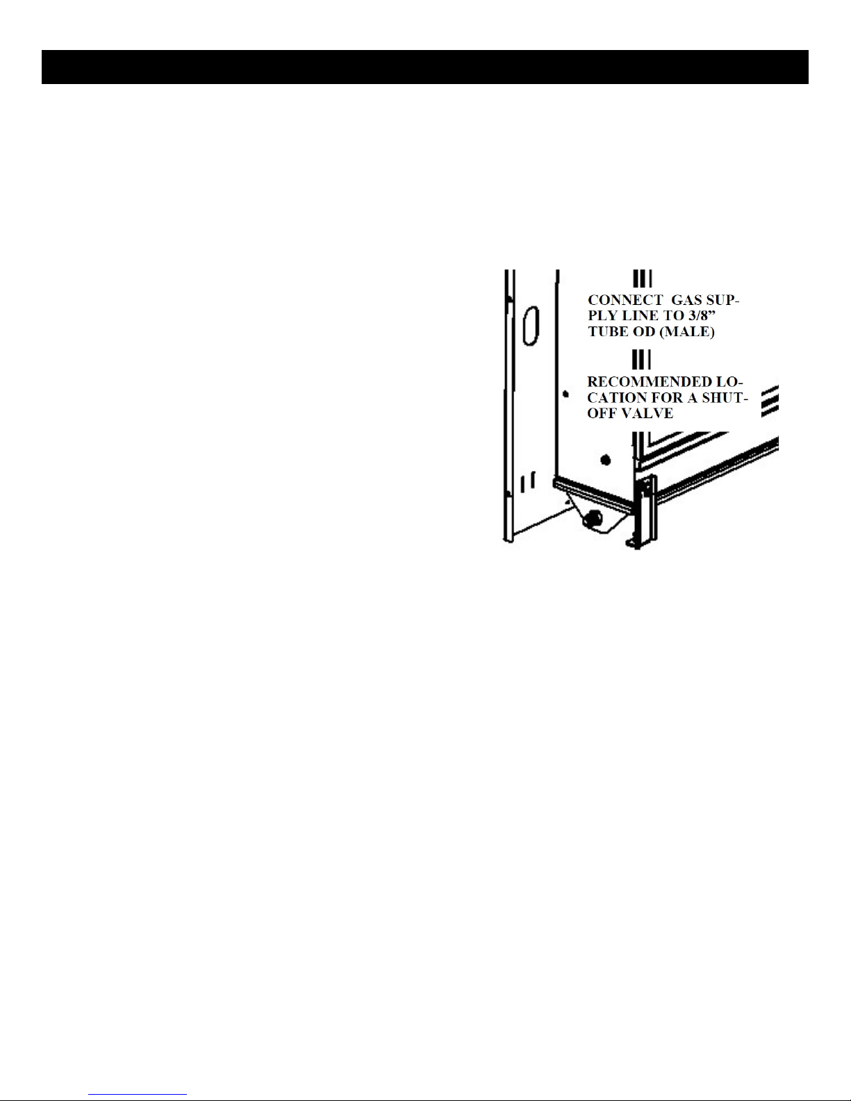
The gas fireplace is shipped with a 3/8” tube OD (male) connection. The gas supply piping should
have a separate gas shutoff valve and a 1/8” NPT plugged tapping upstream of the valve. The stove
and its main control valve must be disconnected from the gas supply piping system during any
pressure testing of that system at test pressures in excess of 1/2 psi (3.5 kPa). The stove must be
isolated from the gas supply piping system by closing the main control valve during any pressure
testing of the gas supply system at test pressures equal to or greater than 1/2 psi (3.5 kPa). After the
gas supply has been connected, use a commercial gas leak detector or apply a soapy water solution
to all the fittings to check for gas leaks. Never use a flame to test for leaks.
7
Page 9

SPECIFICATIONS
MINIMUM CLEARANCES TO COMBUSTIBLE CONSTRUCTION
Slim 26 VF Slim 46 VF
Fireplace to Left Side Wall - (Dimension “A”) 6”
6”
Fireplace to Right Side Wall - (Dimension “A”) 6” 6”
Fireplace to Corner Side Wall - (Dimension “B”) 6” 6” *
Fireplace to Ceiling (Dimension “C”) 12” 12”
Fireplace to Floor (Dimension “D”) 3” ** 3” **
Fireplace to Rear Wall 0” *** 0” ***
Air Space Behind Mounting Plate (Dimension “E”) 5/16” 3/8”
Floor to Ceiling Overall Minimum Dimension 42 ¼” 40 ¼”
*Optional Corner Kit not available for the Slim 46 VF
**The minimum required clearance to be maintained from the fireplace to combustible flooring is measured from the top
surface of carpeting, tile, etc.
***Mounting plate bosses contact the wall.
8
Page 10

SPECIFICATIONS
CERTIFICATION
OMNI-Test Laboratories, Inc. has certified that the SPARK Fire Ribbon Vent Free Gas Fireplace meet the
ANSI Z21.11.2-2013 standard.
These appliances are approved for installation in the Commonwealth of Massachusetts. The Board of
State Examiners of Plumbers and Gas Fitters has issued approved these appliances.
Sample Rating Label (affixed to RH side of firebox)
9
Page 11

ASSEMBLY & INSTALLATION
UNPACKING AND INSTALLING THE SPARK FIRE RIBBON GAS FIREPLACE
LIFT OFF FIRST
The fireplace components are shipped in two
cartons. By now, you will have opened the top of the
first carton and removed the front face protector and
this Manual. The second carton contains the fireplace
surround assembly.
1. Using the adjacent illustrations as a guide,
first lift and remove Tube 1 from the carton
containing the firebox. Carefully unpack the
contents of the tube and set aside. This
should include the bag of glass burner
media, the remote control handset, and a
hardware bag.
2. Next lift and remove Tube 2 from the
carton. Carefully remove the contents of
the tube. This includes the four decorative
panels that will be attached to the fireplace
during assembly.
3. Next, remove all remaining packing
material from the carton.
FACE PROTECTOR
4. Lift the firebox and the fireplace mounting
plate as a unit up and out of the carton. The
best place to lift is at sides. Remove the
fireplace mounting template from the face
of the fireplace. You should now have all of
the parts as shown in the illustration below.
5. Finally, unpack the fireplace surround from
the third carton and set aside on a soft
surface for later use.
10
Page 12

ASSEMBLY &
INSTALLATION
Before you begin the fireplace mounting process there are several important installation requirements
that must be met. Careful planning will make the installation easier to accomplish and will reduce the
chances of encountering problems during installation.
1. The fireplace is designed to be wall-mounted using four lag bolts to secure the fireplace
mounting plate to the wall structure. The mounts are located 16” on center and 24” on center to
correspond with standard building construction. If your home has non-standard construction or
the location you have chosen for the fireplace does not have wall studs that correspond to
location of the fireplace mounts, modifications to the wall structure will be needed. It is critical
that the four lag bolts that are provided for mounting the fireplace are firmly imbedded into the
wall structure at all four locations.
2. All required minimum clearances to adjacent combustible materials (including side walls, ceiling
and floor) must be achieved with the location you have chosen. See the clearance information on
page 8. The listed clearances are measured from the outermost front edges of the fireplace
surround and not from the fireplace body or mounting plate. Again, plan the installation in
advance to avoid problems.
3. The gas supply line must be located within a specific area behind the fireplace. Use the provided
wall template as a guide when locating the gas supply line pass-through.
Once you are certain that the location you have chosen meets all the necessary mounting and safety
requirements, you can begin the installation.
1. Tape or pin the installation template to
the wall in the position where the fireplace
is to be mounted. Note: It is important
that the fire-place is mounted in a level
position. Use a spirit level placed on the
cross-hairs in the upper mounting holes
on the template and adjust the template
position until the mounting holes are
level. Refer to the adjacent illustration.
2. Next, carefully transfer the location of the
two upper and two lower mounting holes
that you will use for your installation. Use
a sharp nail, awl or pin to pierce the
template on the mounting hole crosshairs to insure an accurate transfer to your
wall.
3. Finally, transfer the location of the gas supply line.
4. Remove the template and circle the transferred locations with a pencil or marker.
11
Page 13

ASSEMBLY & INSTALLATION
GAS SUPPLY LINE
INSTALLING THE FIREPLACE
MOUNTING PLATE ON THE WALL
The supply line should exit the wall that the fireplace will be installed on at the location specified on the
installation template we suggest the installation of a shut-off valve in the supply line between the wall
and the connection to the fireplace. Your professional gas installer or local gas company will determine
the specific requirements for the gas supply line as the requirements may vary in different locations. In
every case, the installation must conform with local codes or, in the absence of local codes, with the
National Fuel Gas Code, ANSI Z223.1.
1. The fireplace mounting plate is attached to
the wall structure using four 1/4” X 1 1/2”
long lag bolts and large diameter washers
that are provided with the fireplace. It is
important to use the included hardware as
the full weight of the fireplace is supported
by the mounting plate.
2. Drill a 5/32” diameter pilot hole at each of
the mounting hole locations that you
marked using the template. The pilot holes
should be the full depth of the lag bolts. Be
sure that there is solid wood at each
mounting location. If not, the wall should
be reconstructed to provide the needed
support.
3. With a helper pick up and align the mounting plate over the gas supply line and line up with the
four mounting lag bolt pilot holes. These holes are in recessed bosses. Use either the 16” or 24”
on center holes depending on the construction of the wall.
4. Using the lag bolts and washers provided with the fireplace, install the top lag bolts (with
washers) first, followed by the lower ones. Use a 7/16” socket wrench to tighten the lag bolts.
Note: It may be helpful to put a light coating of dish or hand soap on the lag bolts to reduce
resistance when tightening.
5. At this point, check to be sure that there is an air gap between the entire flat back surface of the
mounting plate and the wall surface (see clearance chart on page 9 for the air gap required for
your model). This gap is critical to a safe installation and if the gap is obstructed in any way,
remove the obstruction before proceeding.
6. Next check that the brackets on the mounting plate that actually hold the fireplace are level,
again using a spirit level. If the brackets are not perfectly level, you can adjust the right bracket
by loosening the bracket fasteners and moving the bracket until it is level with the left bracket.
Remember to tighten the bracket fasteners once you have achieved a level position. (refer to
images on following page)
12
Page 14

ASSEMBLY & INSTALLATION
7. You are now ready to install the fireplace on the mounting plate, this will require a helper as the
fireplace is quite heavy.
8. While looking in from the sides, guide the
upper and lower mounting tabs on the back
of the fire-place into the corresponding
brackets on the mounting plate. When the
tabs and brackets are aligned, push the
fireplace down and in to engage the tabs in
the brackets. Note: The weight of the
fireplace is carried only on the top brackets.
The bottom brackets function simply to keep
the bot-tom of the fireplace from moving.
Refer to the adjacent illustration.
9. Once more, confirm that the fireplace is level using the spirit level used in the preceding steps.
The fireplace is now ready for the gas connection to be made.
13
Page 15
ASSEMBLY & INSTALLATION
GAS CONNECTION
1. Verify that the gas type is correct for the fireplace by looking at the rating plate that is attached
to the right side of the fire-place, adjacent to the control battery pack. Note: The fireplace is
shipped from the factory equipped to burn the fuel listed on the rating plate. Fuel conversion in
the field is not allowed.
2. The gas connection should now be made from the gas supply line to the 3/8 OD Tube fitting on the
fireplace. Only a qualified gas installer is to make the connection.
3. The gas supply piping should have a separate
gas shut-off valve and a 1/8” NPT plugged
tapping upstream of the valve. We recommend
installing a shut-off valve between the gas
supply line where it penetrates the wall /
fireplace mounting plate and the inlet on the
fireplace. This will allow gas to be shut-off to
the fireplace by simply removing the fireplace
surround to gain access to the shut-off valve.
4. The fireplace and its main burner valve must be
disconnected from the gas supply piping
system during any pressure testing of that
system at test pressures in excess of 1/2 psi
(3.5kPa).
5. The fireplace must be isolated from the gas supply piping system by closing the gas shut-off
valve during any pressure testing of the gas supply system at test pressures equal to or less than
1/2 psi (3.5kPa). After the gas supply has been connected, use a commercial gas leak detector or
apply a soapy water solution to all the fittings to check for gas leaks. Never use a flame to test for
leaks.
14
Page 16
ASSEMBLY & INSTALLATION
INSTALLING OR REPLACING THE BATTERIES
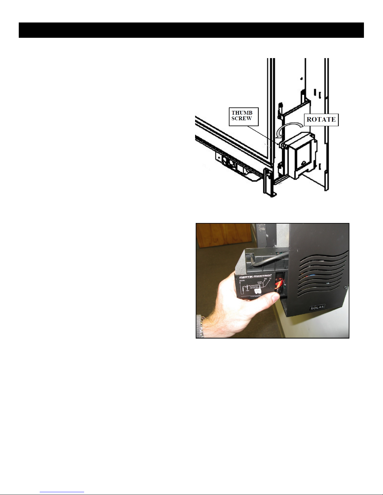
1. The valve control module is powered by
four “AA” batteries. The batteries are
mounted within the Valve Receiver Module
located on the right side of the fireplace
attached to a drop-down mounting bracket
for easy accessibility. Refer to the adjacent
illustration.
2. Loosen the thumb screw on the module
drop-down mounting bracket by turning
counter-clockwise until the threads are
fully disengaged from the base bracket.
3. Rotate the Valve Receiver Module and
mounting bracket. Toward you 90 degrees.
4. Slide off the Battery compartment cover.
5. Install the 4 “AA” batteries, supplied, using
the guides inside the battery pack to show
you the correct battery orientation.
6. Replace the battery compartment cover.
Rotate the Valve Receiver Module and
mounting bracket into its home position
and tighten the thumb screw to secure.
7. The remote handset is powered by three
“AAA” batteries. The access panel is located
on the back of the handset and simply
snaps open to provide access to the battery
compartment. Install the three batteries as
shown on the label inside the remote
control battery compartment.
8. Replace the remote handset access panel.
15
Page 17
ASSEMBLY & INSTALLATION
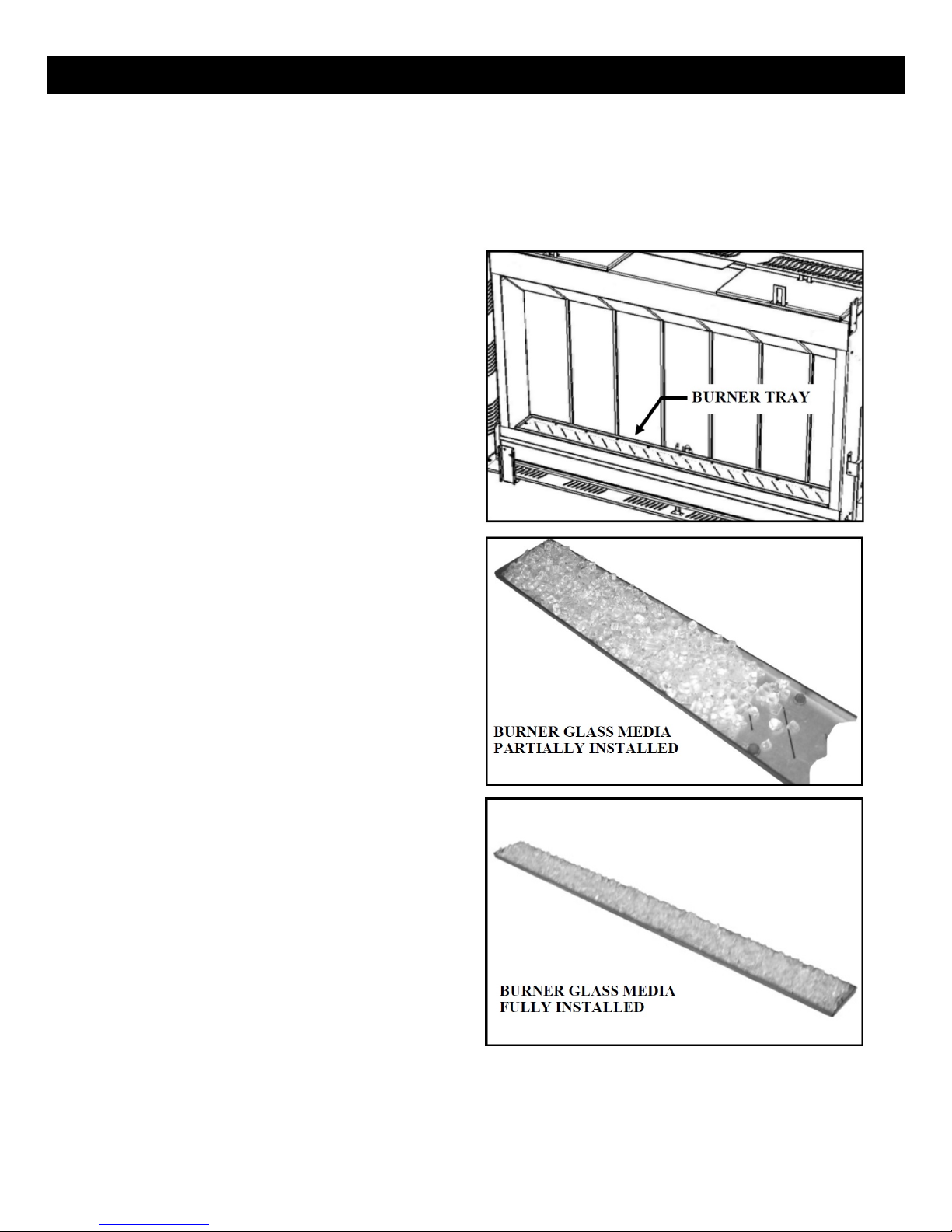
PLACING THE BURNER GLASS MEDIA
The burner glass media poly-bag that you set aside when you unpacked the fireplace contains the
correct amount of glass material to cover the burner. DO NOT add any additional media to the media
supplied with your fireplace. The entire contents of the bag should be evenly distributed over the burner
tray.
1. Locate the burner in the fireplace. Refer to
the adjacent illustration.
2. Carefully clip one corner of the poly-bag to
form a pouring spout. The opening should
be large enough to allow the glass media to
flow but not so large that you can’t control
the flow.
3. You will notice that the burner surface is
designed with turned-up edges that form a
tray to hold the glass media.
4. Starting at one end, pour the glass media
onto the burner tray, keeping the pouring
spout on the poly-bag toward the center of
the burner to avoid spillage of glass pieces
over the sides of the burner. See the
adjacent illustrations.
5. Once you have poured all of the glass
burner media into the burner tray, carefully
smooth the glass pieces out so they have a
uniform depth over the entire surface of
the burner. When the burner glass media is
properly placed, it should look like the
adjacent illustrations.
Note: If a few pieces of glass escape over the edges
of the burner tray during installation, it is not a
problem. They will simply land in the area below
the burner and will do no harm.
16
Page 18
ASSEMBLY & INSTALLATION
INSTALLING OUTER PANELS
1. The four outer decorative panels are
secured to the fire-place with Philips head
screws. The top and bottom panels are
secured to the fireplace mounting plate
with sheet metal screws. All other screws
are Philips head machine screws.
2. Install the top panel first. Align the three
holes along the rear edge of the panel with
pilot holes along the top edge of the
fireplace mounting plate.
3. Insert and tighten the three sheet metal
screws. A magnetic nut driver is helpful.
4. Install the left side panel next. Align the
three holes along the rear edge of the panel
with the PEM nuts along the edge of the
fireplace mounting plate. Insert the three
Philips head screws but do not fully
tighten.
5. Locate the fastener hole at the top front
edge of the left side panel and align with
the PEM nut in the front of the top panel.
Insert the Philips head screw.
6. Make sure the edges of the panel are aligned with the edges of the top panel and mounting plate
and tighten all four Philips head screws.
7. Position the right side panel so it aligns with the three PEM nuts on the mounting plate and the
front PEM nut on the top panel. Align the rear and top panel edges with the adjoining parts and
insert and tighten the four Philips head screws.
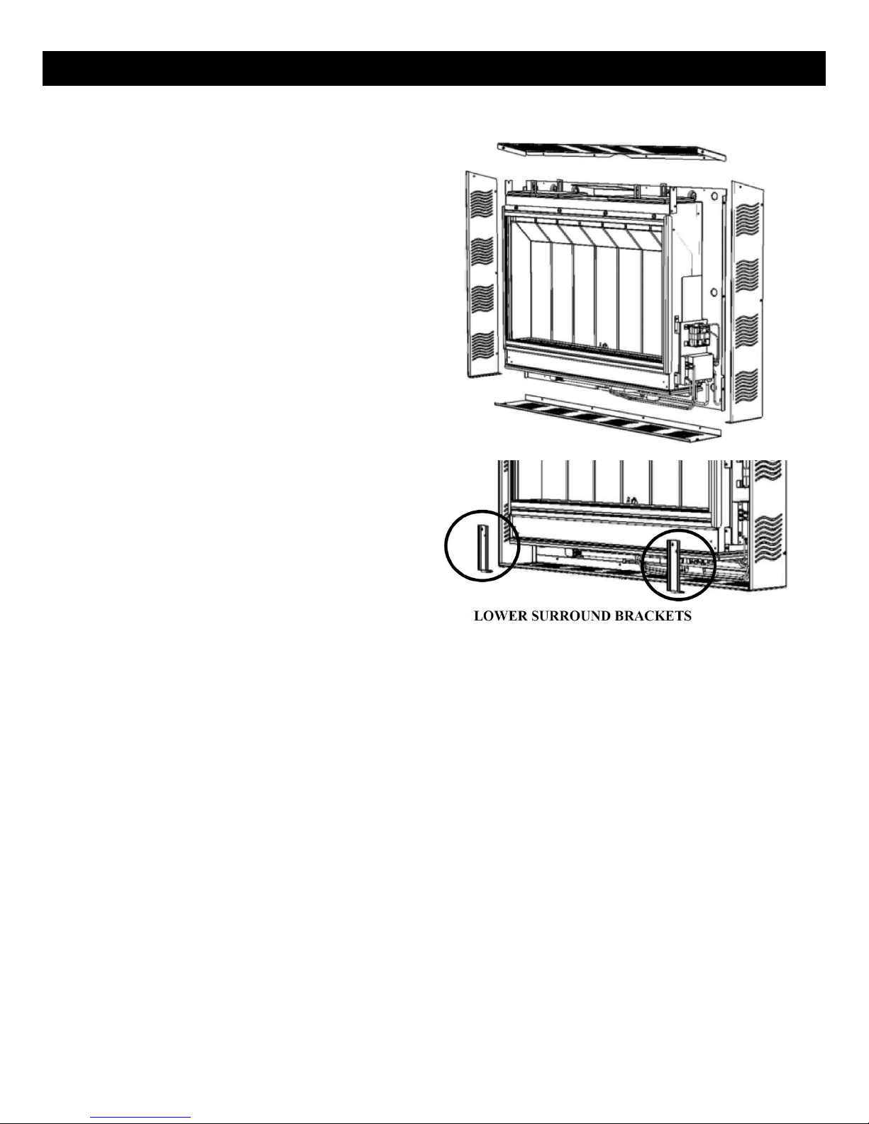
8. Install the bottom panel next. Guide the rear flange on the panel upward until the mounting
holes in the flange line up with the pilot holes in the mounting plate.
9. Attach the panel to the mounting plate using sheet metal screws along the back edge of the
panel. Note: It may make installation of the sheet metal screws easier if you remove the two
lower surround mounting brackets from the front of the fireplace, replace brackets before
operating fireplace. A magnetic nut-driver will also be helpful.
10. Attach the bottom panel to the side panels by aligning the fastener holes in the bottom panel
with the PEM nuts in the front corners of the bottom flanges on the side panels. Insert and
tighten the two Philips head screws.
Only trim kit(s) supplied by the manufacturer shall be used in the installation of this appliance.
17
Page 19
ASSEMBLY & INSTALLATION
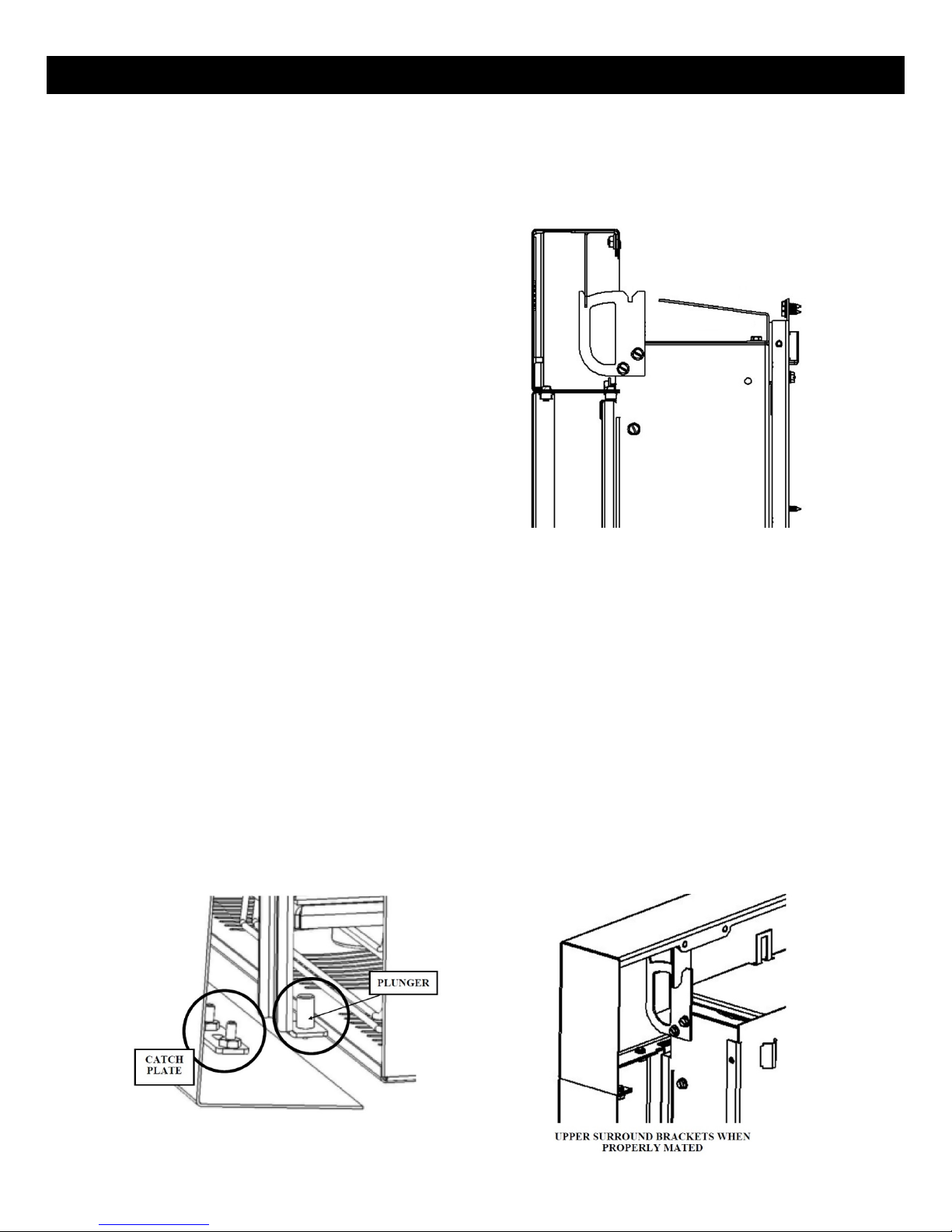
INSTALLING THE FIREPLACE SURROUND WITH INTEGRATED SCREEN
The decorative surround with integrated screen for the fireplace is held in place by four brackets. Two
are located on the top of the fireplace and two on the bottom. There are mating brackets and catch
plates on the surround itself. Refer to the adjacent illustrations when installing the surround.
1. Unpack the surround with integrated
screen from shipping box.
2. With a helper, lift the surround with
integrated screen up and identify the top
by looking for the vertical brackets that are
visible from the rear of the surround.
3. Move the surround with integrated screen
into place, generally centering the
surround opening over the glass panel.
Keep the bottom of the surround tipped
slightly away from the fireplace.
4. While looking behind the surround with integrated screen, guide the two surround brackets onto
the for-ward detent of the mating brackets on the fireplace top. You might find it easier to
engage one bracket and then the other. Lower the surround until both bracket sets are fully
mated.
5. Carefully push the top of the surround with integrated screen so that the surround brackets slide
into the rear detent of the mating brackets on the fireplace top. Carefully swing the bottom of
the surround with integrated screen toward the base of the fireplace until the catch plates on the
bottom flange of the surround are aligned with the spring loaded plungers on the bottom flanges
of the lower surround mounting brackets.
6. To remove the surround with integrated screen, pull the bottom edge of the surround outward to
disengage the spring loaded plungers and then lift the top up and off the upper brackets.
7. To prevent damage to the surround with integrated screen, always set the surround with
integrated screen in a safe place while it is removed from the fireplace.
18
Page 20

LIGHTING & OPERATION
WARNING: If you do not follow these instructions exactly, a fire or explosion may result causing
property damage, personal injury or loss of life.
When lighting this appliance, follow these instructions exactly.
A. This appliance is equipped with an ignition device that automatically lights the pilot. Do not try to light the pilot by
hand.
B. BEFORE OPERATING THE BURNER SYSTEM, smell around the appliance area for gas. Be sure to smell next to the floor
because some gas is heavier than air and will settle on the floor.
WHAT TO DO IF YOU SMELL GAS
• Do not try to light the appliance.
• Do not touch any electric switch; do not use any telephone in your building.
• Immediately call your gas supplier from a neighbor’s telephone. Follow the gas supplier’s instructions
• If you cannot reach your gas supplier, call the fire department.
C. Use only your hand to operate the gas controls. Never use tools. If a knob will not push in or turn by hand, don’t try to
re-pair it, call a qualified service technician. Force or attempted repair may result in a fire or explosion.
D. Do not use this appliance if any part has been under water. Immediately call a qualified service technician to inspect
the appliance and to replace any part of the control system which has been under water.
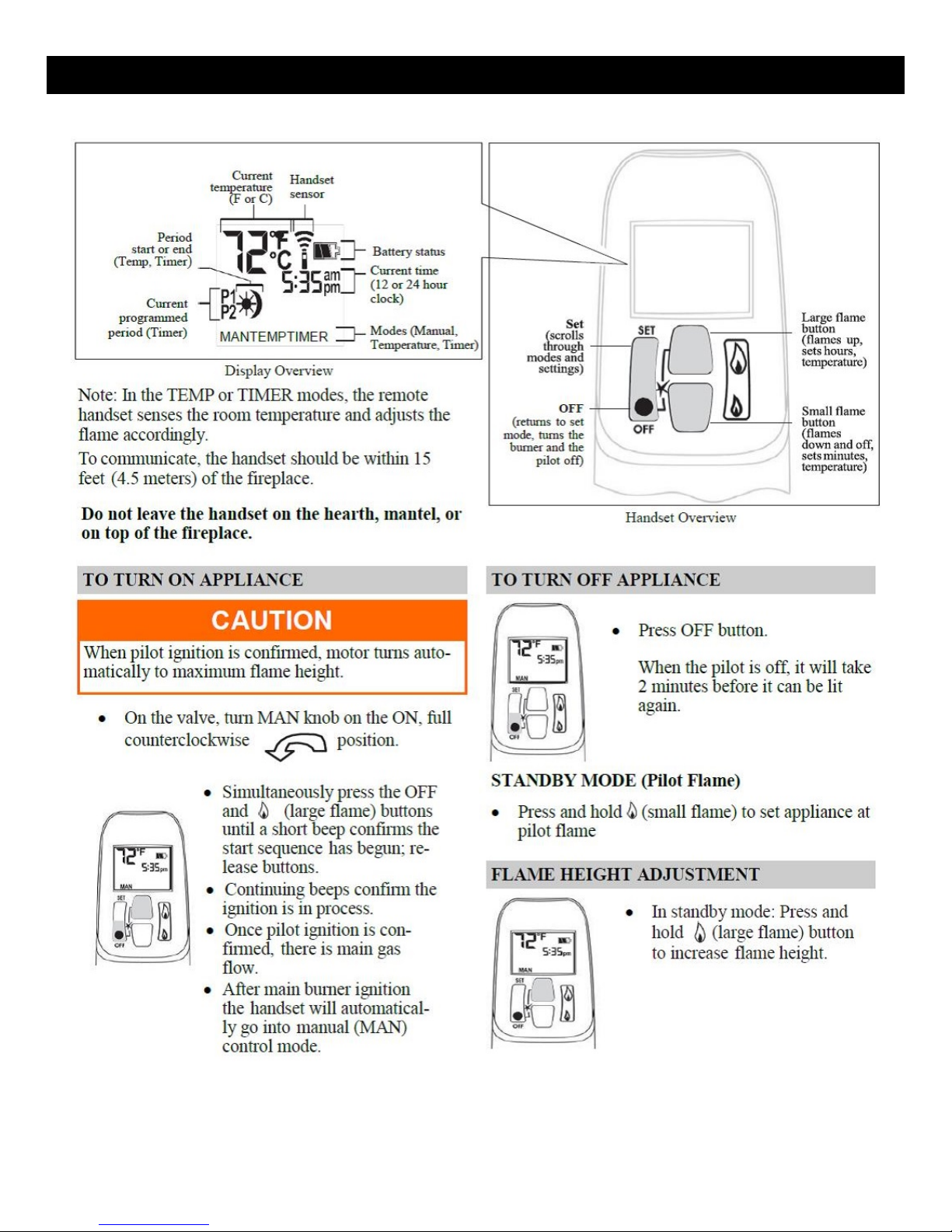
OPERATING INSTRUCTIONS
1. STOP! Read the safety information above on this label.
2. This appliance is equipped with an ignition device that automatically lights the pilot. Do not try to light the pilot by
hand.
3. Using the Remote Handset, or the optional Wall Switch, push the “OFF” button until you hear an audible signal to
insure the appliance is off.
4. Wait five (5) minutes to clear out any gas. Then smell for gas including near the floor. If you smell gas, STOP! Follow
“B” in the safety information above. If you don’t smell gas, proceed to step 5.
5. Using either the Remote Handset, or the optional Wall Switch, simultaneously press the “ON” and
“High Flame” buttons. An audible signal confirms the start sequence has begun.
6. Continuing beeps confirm the ignition is in process. Once lighting the pilot flame should appear as shown in Fig.2.
Once the pilot is confirmed, the main burner ignites on high.
NOTE: If the pilot does not stay lit after several tries, proceed to step 9.
7. Use the flame height adjustment buttons on either the Remote Handset or the optional Wall Switch to adjust the
flame. Press the button twice to decrease the flame height to its lowest setting, press the button twice to
increase flame height to the highest setting. Pressing the or button once will modulate the flame to intermediate
settings. The Remote Handset can also be used to control the appliance thermostatically.
8. Press and hold the button on the Remote Handset or optional Wall Switch to set the appliance to Pilot flame only.
9. If the appliance will not operate, follow the instructions “TO TURN OFF GAS TO THE APPLIANCE” and call your gas
service technician or gas supplier.
TO TURN OFF GAS TO THE APPLIANCE
1. To turn off gas to the appliance,
push and release the “OFF”
button on either the Remote
Handset or the optional Wall
Switch. An audible signal will
confirm.
2. TO TURN OFF THE GAS SUPPLY
TO THE APPLIANCE, close the
shut-off valve on the gas supply
line to the appliance.
19
Page 21
LIGHTING & OPERATION
OPERATING YOUR FIREPLACE FOR THE FIRST TIME
When operating your new fireplace for the first time, some vapors may be released due to the curing
compounds used in the manufacture of the appliance. They may cause a slight odor and could cause
the flames to be the full height of the firebox, or even slightly higher, for the first few hours of operation.
It is also possible that these vapors could set off and smoke detection alarms in the immediate vicinity.
These vapors are quite normal on new appliances. We recommend opening a window to vent the room
during the burn off period. After a few hours use, the vapors will have disappeared and the flames will
be at their normal height.
FLAME SUPERVISION DEVICE
For your safety, this appliance is fitted with a flame supervision device which will shut-off the gas supply
if, for any reason, the pilot flame goes out. This device incorporates a fixed probe, which senses the heat
from the pilot flame. If the probe is cool, the device will prevent any gas flow unless manually lighting
the pilot. See full lighting instructions. Periodically check the pilot and burner flames, comparing them
to figure 2 on the preceding page, and the image at the bottom of this page.
LIGHTING, OPERATION, AND RATING
INFORMATION
The Lighting, Operation and Rating information is
located on a plate on the RH side of the firebox.
To access the plate, remove the surround and grab the plate and slide it up to read it. There is important
information on both sides of the plate.
SERVICING
If any attention is required for your appliance, contact your dealer quoting the model number. It will be
helpful if the appliance’s serial number can also be quoted. This number is on the rating plate, which is
located under the burner. The replacement parts are shown at the end of this manual. Please always
quote the part number and description when requesting spare parts.
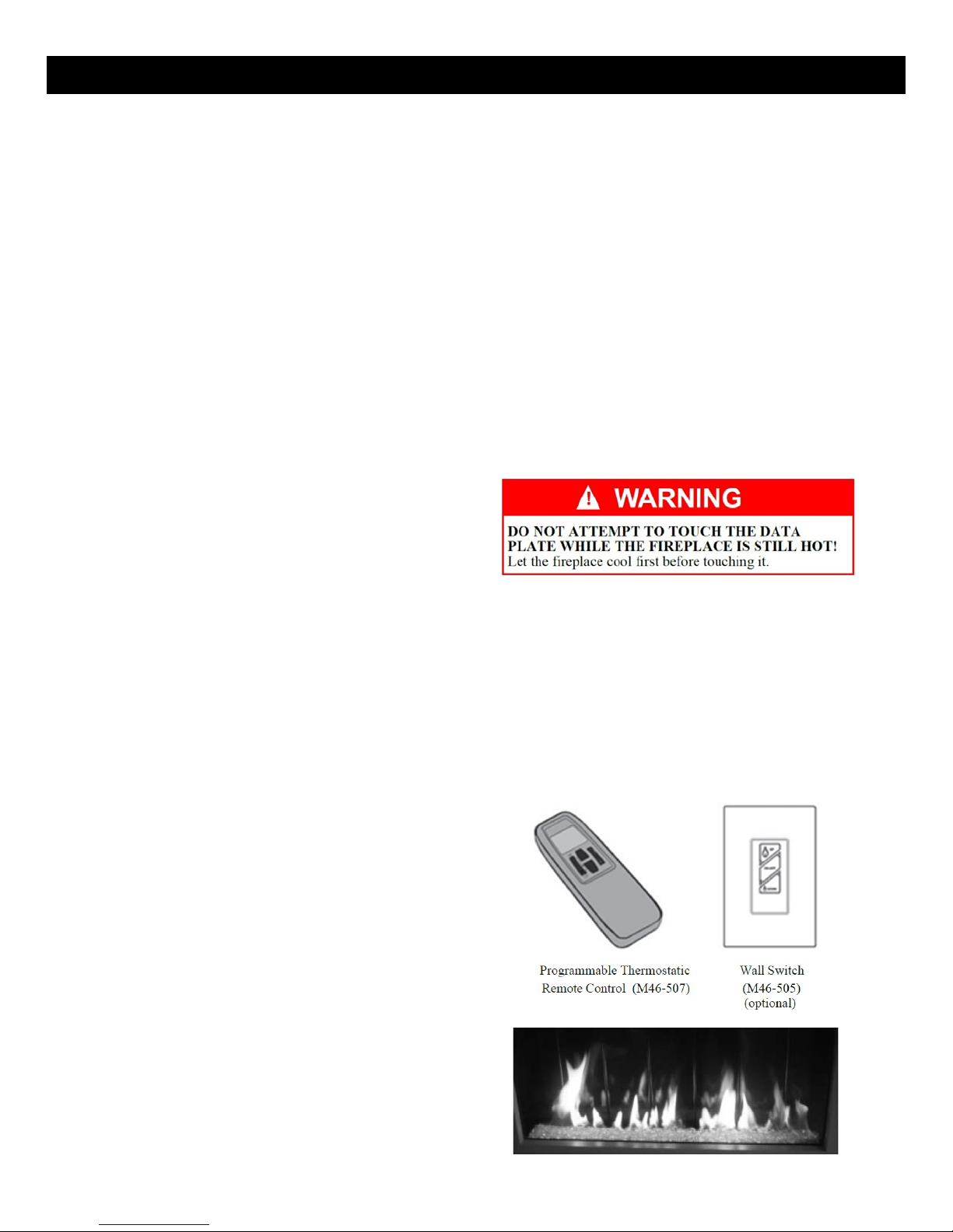
FIREPLACE CONTROL DEVICES
There are two ways to control your fireplace.
1. Thermostatic Remote Control (M46-507)
2. Optional Wall Switch (M46-505)
The Thermostatic Remote Control can be
programmed to function automatically—see
pages 21-27.
The Wall Switch (optional) can be used to turn
the flame on, off, and to increase or decrease the
flame height—see M46-505 —Wall Switch Kit.
NOTE: The remote control in the AUTO mode
will override the optional wall switch.
20
Page 22
REMOTE HANDSET OPERATION
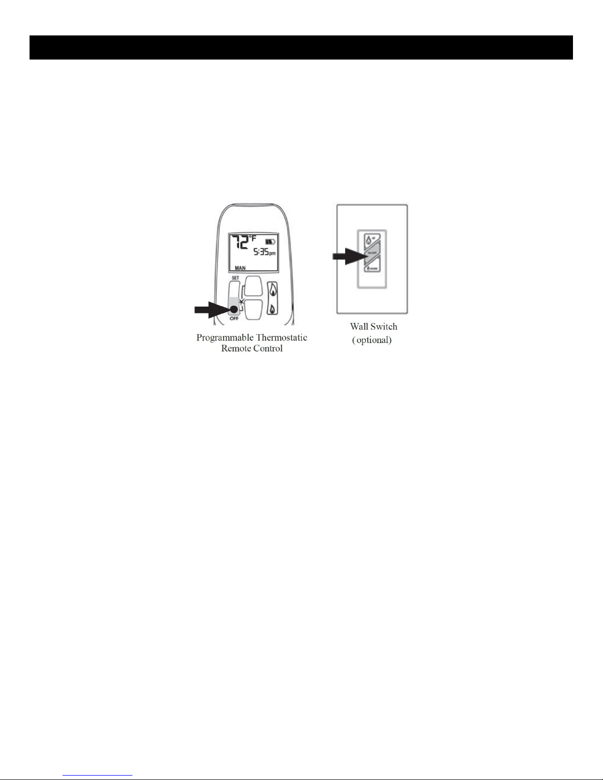
HOW TO TURN YOUR FIREPLACE OFF
HOW TO ENSURE YOUR FIREPLACE CANNOT BE TURNED ON INADVERTENTLY
(INCLUDING PILOT)
Familiarize yourself with each of these methods before operating your fireplace.
Handset and Wall Switch: Press and hold the OFF button for a second (either on the handset or the
wall switch).
If the flames are on, they go down and you hear the valve motor wind down. You hear a clunk and a
beep indicating that the valve has received the signal from the remote control.
You can use the following method to ensure that your fireplace will not turn on when you don’t want it
on.
First, ensure your replace is turned off—including the pilot—and cold BEFORE going ahead.
• Close the shut-off valve on the gas supply line to the appliance.
• Remove all batteries from the receiver as well as the battery from the handset.
Automatic Shut-Off (in certain conditions)
Your fireplace’s remote control is equipped with an automatic shut-off mechanism which is activated in
certain conditions. See page 27 in the Remote Control Operation section for a description of this feature.
NOTE: Before using the remote control system for the first time, the receiver and the handset are
synchronized at the factory. See the section Remote Control Initial Set-up on page 24 of this manual if the
receiver and handset lose synchronization.
IMPORTANT: BEFORE YOU BEGIN, please note that on this system, the settings of time, temperature and
automatic ON/OFF can only be programmed when the function display is flashing. Be patient when
programming as it can take a few seconds to set.
21
Page 23
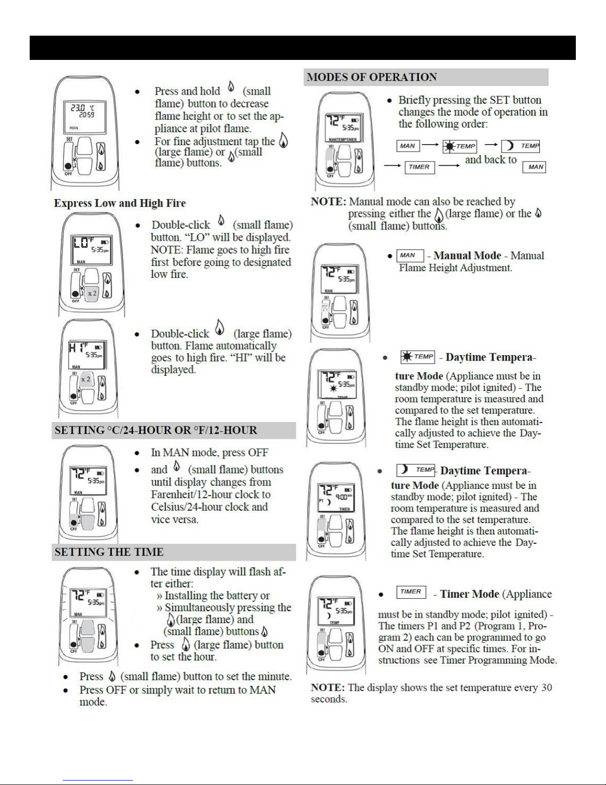
REMOTE HANDSET OPERATION
22
Page 24
REMOTE HANDSET OPERATION
23
Page 25
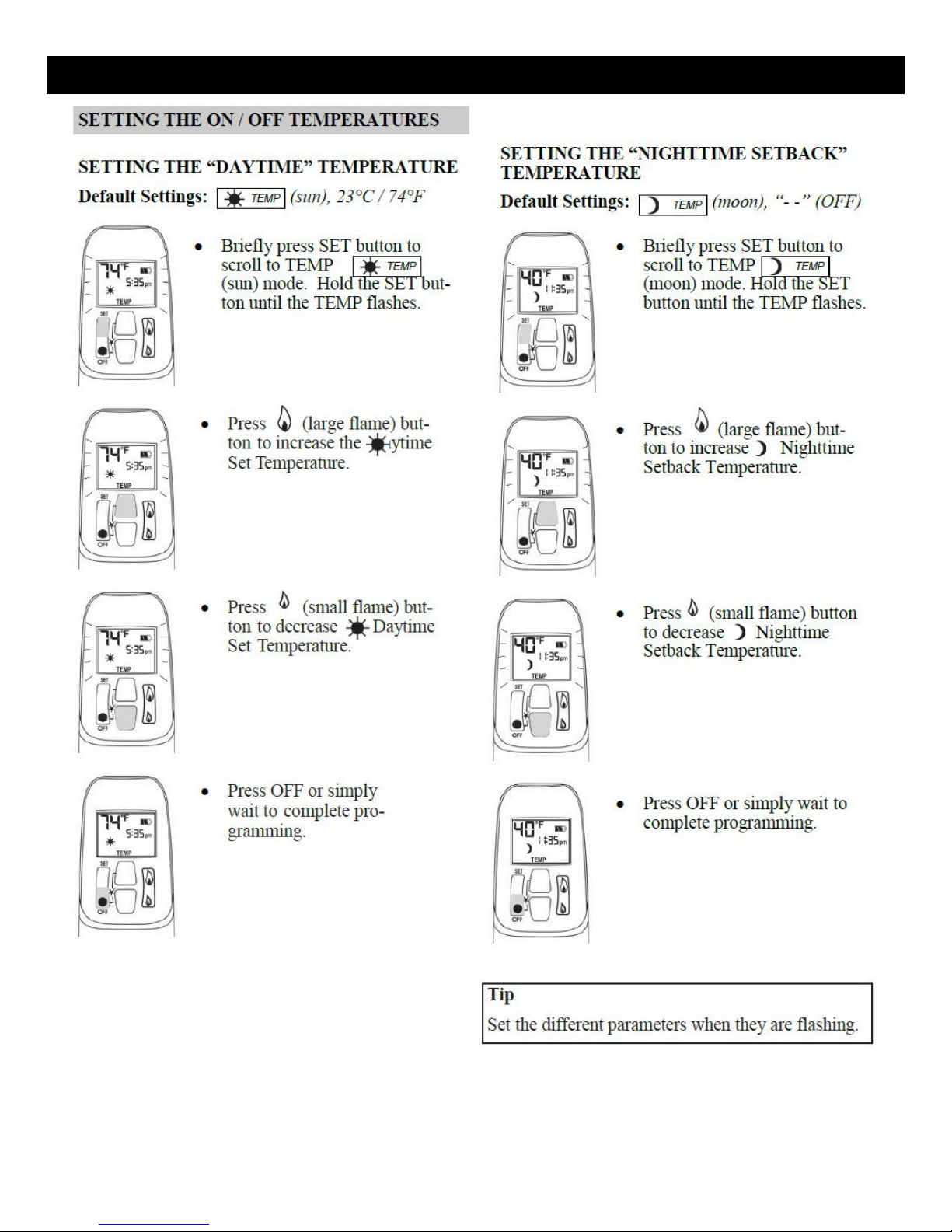
REMOTE HANDSET OPERATION
24
Page 26

REMOTE HANDSET OPERATION
25
Page 27
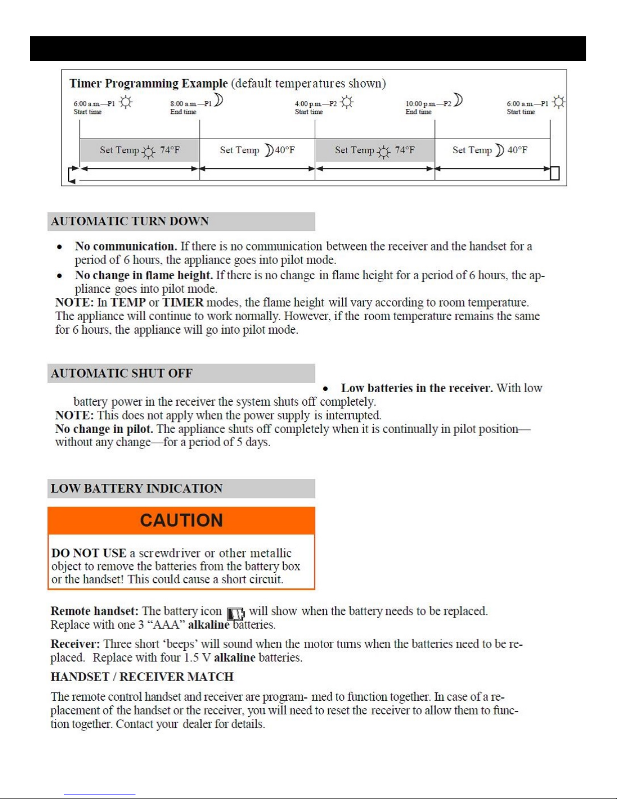
REMOTE HANDSET OPERATION
26
Page 28

MAINTENANCE
ANNUAL MAINTENANCE
CLEANING THE BURNER AND FIREBOX
AIR FLOW
CLEANING THE GLOSS BLACK ENAMEL PANELS
A qualified service agency should conduct an annual inspection and maintenance of your SÓLAS Wall
Mount Vent Free Gas Fireplace including the overall installation and venting to keep it running safely.
The following procedures should be per-formed only by a qualified service person. The gas supply
should be turned off and the stove should be completely cool whenever a maintenance procedure is
performed. All parts of the appliance that are removed for servicing must be replaced prior to operation.
This appliance should be inspected before use and at least annually by a qualified service
person. More frequent cleaning may be required due to excessive dust or lint from carpeting,
bedding materials, pets, etc. It is imperative that control compartments and circulating air
passageways of this appliance be kept clean.
During the annual inspection and maintenance appointment, the service person should clean the
burner and firebox. To gain access to the firebox and burner, follow the instructions beginning on page
18 of this manual.
DO NOT USE A VACUUM CLEANER TO CLEAN THE GLASS BURNER MEDIA.
A vacuum cleaner may be used to clean the metal parts of the firebox. Leave the glass burner media in
place. Use a soft brush to clean the burner glass media. If the burner media does need to be removed,
carefully scoop it off the burner and avoid dropping glass pieces in the air gaps around the burner.
Follow the instructions on page 16 of this manual when replacing the burner media on the burner top.
The SÓLAS Wall Mount Vent Free Gas Fireplace utilizes a convection air heat exchange system to
maximize heat delivered from the fire-place. It is important that air flows freely through the convection
air system and out the top and side air grills. Do not place objects under the fireplace that will block the
convection air inlet flow or in front of any air outlet.
After allowing the Fireplace to cool, use an ammonia-free glass cleaner and a soft, clean cloth to clean
the Enamel Panels at the rear and side of the firebox. It is recommended that the Enamel Panels be
cleaned at least annually to avoid discoloration. More frequent cleaning may be required if
contaminants are present in the gas supply or general atmosphere.
WARNING: Never clean the Enamel Panels while they are hot. Do not use abrasive cleaners or cleaners
containing ammonia.
NOTE: It is recommended that a Micro-fiber cleaning cloth be used to clean the enamel panels.
WARNING: Failure to keep the primary air openings of the burner clean may result in sooting and
property damage.
27
Page 29

MAINTENANCE LOG
We strongly recommend that you keep a log of the regular maintenance that is performed on your
fireplace. We have provided the forms below to make it easy. Simply ask your qualified service per-son
to fill out one of the maintenance record forms below, each time the fireplace is serviced. This will help
insure that all of the required maintenance procedures have been completed, at least annually. Regular
maintenance will help keep the fireplace functioning in a safe and reliable manner. Additional forms are
available from your installer or service person when needed.
28
Page 30

REPLACEMENT PARTS LIST
GENERAL REPLACEMENT PARTS
Natural Gas (NG) Pilot Assembly
VF-401
TC Line Red
M46-701
Propane (LP) Pilot Assembly
VF-402
TC Line Yellow
M46-702
Receiver Module (Maxitrol)
M46-504
Thermocouple Interrupter Block
M46-703
Wall Switch Panel (Optional)
M46-505
8-Wire Connecting Cable
M46-704
Remote Handset (Maxitrol)
M46-507
Gas Valve (Maxitrol)
M46-515
SLIM 26 VF - REPLACEMENT PARTS
Burner Orifice (NG)
NGVF-26
Firebox Enamel Panel - Rear
26VF-201
Burner Orifice (LP)
LPVF-26
Firebox Enamel Panel - Left
26VF-202
Burner Glass Media (Clear/Mixed)
26VF-200
Firebox Enamel Panel - Right
26VF-203
Burner Module (NG)
26VF-301
Burner Module (LP)
26VF-302
SLIM 46 VF - REPLACEMENT PARTS
Burner Orifice (NG)
NGVF-46
Firebox Enamel Panel - Rear
46VF-201
Burner Orifice (LP)
LPVF-46
Firebox Enamel Panel - Left
46VF-202
Burner Glass Media (Clear/Mixed)
46VF-200
Firebox Enamel Panel - Right
46VF-203
Burner Module (NG)
46VF-301
Burner Module (LP)
46VF-302
PART NAME P/N PART NAME P/N
PART NAME P/N PART NAME P/N
PART NAME P/N PART NAME P/N
For replacement parts and customer service contact your SPARK MODERN FIRES dealer or:
SPARK Modern Fires
99B Greenwood Ave.
Bethel, CT 06801
(T) 866-938-3846
(F) 203-798-8661
www.sparkfires.com
29
Page 31

CONTROL SCHEMATIC
Caution: Label all wires prior to disconnection when servicing the controls. Wiring errors can cause
improper and dangerous operation. Verify proper operation after servicing.
30
Page 32

INSTALLATION RECORD
The installer should complete the form below that describes the details of the installation. Having this
written record of installation information available will greatly expedite trouble-shooting should any
problem arise with your stove. The installer should keep a duplicate of this form for their records.
Date Purchased: _____________________________________________
Dealer: _____________________________________________
Date Installed: _____________________________________________
Installer: _____________________________________________
Fireplace Model: (circle one) Slim 26 VF Slim 46 VF
Serial Number: _____________________in. WC
Fuel: (circle one) Natural Gas (NG) Propane (LP)
Inlet Pressure (after installation): _____________________________________________
Manifold Pressure (after Installation): High Fire: _____________ in. WC
Low Fire: _____________ in. WC
Altitude: (feet above sea level) _____________________________________________
Was the stove de-rated? (circle one) Yes No
If the stove was de-rated, to what
orifice size?
Other installation notes: _____________________________________________
_____________________________________________________________________________________
_____________________________________________________________________________________
_____________________________________________________________________________________
_____________________________________________
_____________________________________________________________________________________
_____________________________________________________________________________________
_____________________________________________________________________________________
_____________________________________________________________________________________
31
Page 33

WARRANTY INFORMATION
32
Page 34

V1 / 6-16-15
33
 Loading...