

Page 1

SPARK MODERN FIRES
™
UNVENTED (VENT-FREE) GAS FIREPLACE
WITH ELECTRONIC IGNITION SYSTEM
MODELS: 5
OWNER’S OPERATION AND INSTALLATION MANUAL
WARNING: If the information in this manual
is not followed exactly, a fire or explosion
may result causing property damage,
personal injury, or loss of life.
— Do not store or use gasoline or other
flammable vapors and liquids in the
vicinity of this or any other appliance.
— WHAT TO DO IF YOU SMELL GAS
• Donottrytolightanyappliance.
• Donottouchanyelectricalswitch;do
not use any phone in your building.
• Immediately call your gas supplier
from a neighbor’s phone. Follow the
gas supplier’s instructions.
• Ifyoucannotreachyourgassupplier,
call the fire department.
— Installation and service must be
performed by a qualified installer,
service agency, or the gas supplier.
This is an unvented gas-fired heater. It uses
air (oxygen) from the room in which it is
installed. Provisions for adequate combustion and ventilating air must be provided.
Refer to page 4, Air for Combustion and
Ventilation.
8(N,P)
Report # 321-F-10-5
WARNING: Improper installation, adjustment, alteration, service, or maintenance
can cause injury or property damage. Refer
to this manual for correct installation and
operational procedures. For assistance or
additional information consult a qualified installer, service agency, or the gas supplier.
TKLVKHDWHUVKDOOQRWEHLQVWDOOHGLQDURRP
RUVSDFHXQOHVVWKHUHTXLUHGYROXPHRIWKH
LQGRRUFRPEXVWLRQDLULVSURYLGHGE\WKH
PHWKRGGHVFULEHGLQWKH1DWLRQDO)XHO*DV
&RGH$16,=1)3$WKH,QWHUQDWLR
QDO)XHO*DV&RGHRUDSSOLFDEOHORFDOFRGHV
This appliance may be installed in an
aftermarket,* permanently located, manufactured (mobile) home, where not prohibited by local codes.
This appliance is only for use with the type
of gas indicated on the rating plate. This
appliance is not convertible for use with
other gases.
* Aftermarket: Completion of sale, not for purpose of resale, from
the manufacturer
INSTALLER: Leave this manual with the appliance.
CONSUMER: Retain this manual for future reference.
Version française de ce manuel est disponible à partir du site WEB : www.sparkfires.com
Page 2

,QVWDOODWLRQDQGUHSDLUVKRXOGEHGRQHE\DTXDOLILHG
TABLE OF CONTENTS
VHUYLFHSHUVRQ7KHDSSOLDQFHVKRXOGEHLQVSHFWHG
EHIRUHXVHDQGDWOHDVWDQQXDOO\E\DSURIHVVLRQDO
VHUYLFHSHUVRQ0RUHIUHTXHQWFOHDQLQJPD\EHUHTXLUHG
GXHWRH[FHVVLYHOLQWIURPFDUSHWLQJEHGGLQJPDWHULDO
HWF,WLVLPSHUDWLYHWKDWFRQWUROFRPSDUWPHQWVEXUQHUV
DQGFLUFXODWLQJDLUSDVVDJHZD\VRIWKHDSSOLDQFHEH
NHSWFOHDQ
This unit was tested and listed to
Z21.11.2-20
This appliance is equiped for (natural or propane) gas.
Field conversion is not permitted.
by OMNI-Test Laboratories.
WARNING
ANSI
Safety Information .............................................. 3
Local Codes
Locating Firebox ................................................ 5
Product Specifications........................................ 5
Air For Combustion and Ventilation ................... 6
Installation .......................................................... 8
Framing ............................................................. 1
Operating Fireplace .....................................
, Specifications
................................ 4
.
..... 19
Inspecting Burners ...........................................
Cleaning and Maintenance ................................2
Troubleshooting
Proflame Wiring Diagram
llustrated Parts Breakdown and Parts List ........
Warranty Information ........................... Back Cover
0
.................................................25
...................................2
2
23
30
4
9
Page 3

3
SAFETY INFORMATION
WARNING: This product contains and/or generates chemicals
known to the state of California
to cause cancer or birth defects
or other reproductive harm.
IMPORTANT: Read this owner’s
manual carefully and completely
before trying to assemble,
operate or service this heater.
Improper use of this heater can
cause serious injury or death
from burns, fire, explosion,
electrical shock and carbon
monoxide poisoning.
DANGER: Carbon monoxide
poisoning may lead to death!
Carbon Monoxide Poisoning: Early signs of
carbon monoxide poisoning resemble the flu, with
headaches, dizziness or nausea. If you have these
signs, the heater may not be working properly. Get
fresh air at once! Have heater serviced. Some
people are more affected by carbon monoxide than
others. These include pregnant women, people with
heart or lung disease or anemia, those under the
influence of alcohol and those at high altitudes.
Natural and Propane/LP Gas: Natural and pro-
pane/LP gases are odorless. An odor-making agent
is added to the gas. The odor helps you detect a gas
leak. However, the odor added to the gas can fade.
Gas may be present even though no odor exists.
Make certain you read and understand all warnings.
Keep this manual for reference. It is your guide to
safe and proper operation of this heater.
WARNING: Any change to
this heater or its controls can
be dangerous.
WARNING: Do not use a
blower insert, heat exchanger
insert or other accessory not approved for use with this heater.
WARNING: Do not allow fans
to blow directly into the fireplace.
Avoid any drafts that alter burner
flame patterns. Ceiling fans can
create drafts that alter burner
flame patterns. Altered burner
patterns can cause sooting.
Due to high temperatures, the
appliance should be located out
of traffic and away from furniture
and draperies.
Do not place clothing or other
flammable material on or near
the appliance. Never place any
objects on the heater.
&KLOGUHQDQGDGXOWVVKRXOGEH
DOHUWHGWRWKHKD]DUGRIKLJK
VXUIDFHWHPSHUDWXUHVDQGVKR
XOGVWD\DZD\WRDYRLGEXUQVRU
FORWKLQJLJQLWLRQ<RXQJFKLOGUHQ
VKRXOGEHFDUHIXOO\VXSHUYLVHG
ZKHQWKH\DUHLQWKHVDPHURRP
ZLWKWKHDSSOLDQFH
When using the optional handheld remote accessory, keep
selector switch inside firebox
in the OFF position to prevent
children from turning on burners
ZLWKUHPRWH
Keep the appliance area clear
and free from combustible materials, gasoline and other flammable vapors and liquids.
Page 4

4
1.
This appliance is only for use with the type of
gas indicated on the rating plate. This appliance
is not convertible for use with other gases.
2. Do not place propane/LP supply tank(s) inside any structure. Locate propane/LP supply
tank(s) outdoors (propane/LP units only).
3. If you smell gas
• shut off gas supply
• do not try to light any appliance
• do not touch any electrical switch; do not use
any phone in your building
•
immediately
call
your
gas
supplier
from
a
neighborʼs
phone.
Follow
the
gas supplierʼs
instructions
•
if
you
cannot
reach
your
gas
supplier, call
the fire department
4.
This
fireplace
shall
not be installed in a bed-
room or bathroom.
5.
Do not use this fireplace as a wood-burning
fireplace.
6. To prevent the creation of soot, follow the
instructions in Cleaning and Maintenance
section.
7. Before using furniture polish, wax, carpet
cleaner
or similar products, turn heater off. If
heated, the vapors from these products may
create a white powder residue within burner
box or on adjacent walls or furniture.
8. This fireplace needs fresh air ventilation to run
properly. This fireplace has an Oxygen Depletion Sensing (ODS) safety shutoff system. The
ODS shuts down the fireplace if enough fresh
air is not available. See Air for Combustion
and Ventilation, page 6. If fireplace keeps
shutting off, see Troubleshooting, page 21.
9. Do not run fireplace
• where flammable liquids or vapors are used
or stored
•
under dusty conditions
10. Do not use this fireplace to cook food or burn
paper or other objects.
SAFETY INFORMATION
Continued
11. Do not use fireplace if any part has been
exposed to or under water. Immediately call
a qualified service technician to inspect the
fireplace and to replace any part of the control
system and any gas control which has been
under water.
12. Turn fireplace off and let cool before servicing.
Only a qualified service person should service
and repair fireplace.
13. Operating fireplace above elevations of 4,500
feet could cause pilot outage.
14.
To prevent performance problems in propane/LP
units, do not use propane/LP fuel tanks of less
than 100 lbs. capacity (propane/LP units only).
15.
Provide adequate clearances around air
openings.
LOCAL CODES
Install and use fireplace with care. Follow all local
codes. In the absence of local codes, use the latest edition of The National Fuel Gas Code ANSI
Z223.1/NFPA 54*.
*Available from:
American National Standards Institute, Inc.
1430 Broadway
New York, NY
10018
National Fire Protection
Association, Inc.
Batterymarch Park
Quincy
, MA
02269
State of
Massachusetts: The installa-
tion must be
made by a licensed plumber
or gas fitter in the Commonwealth of
Massachusetts.
Sellers of unvented propane or natural
gas-fired supplemental room heaters shall
provide to each purchaser a copy of 527
CMR 30 upon sale of the unit.
Vent-free gas products are prohibited for
bedroom and bathroom installation in the
Commonwealth of Massachusetts.
Keep the appliance area clear
and free from combustible materials, gasoline and other flammable vapors and liquids.
Page 5

LOCATING FIREBOX
PLANNING
Carefully plan where you will install the firebox. This will save time and money later when you install the
firebox. Before installation, consider the following:
1. Where the firebox will be located. Allow for wall and ceiling clearances (see Installation Clear-
ances, page 9.
2. Everything needed to complete installation.
3. Proper air for combustion and ventilation.
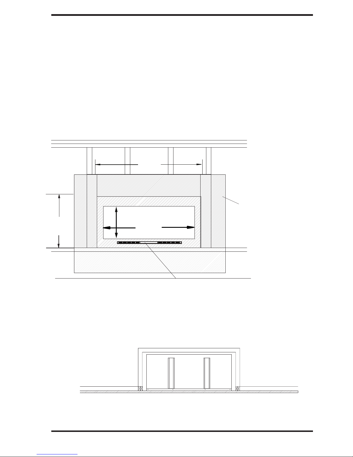
PRODUCT SPECIFICATIONS
FRONT VIEW
60"
48"
RIGHT SIDE VIEW
28.75"
25.75"
TOP VIEW
Model 58N
B
tu ( V ariable)
Type Gas
Ignition
Manifold Pressure 3.5"
W.C. Inlet Gas Pressure (in. of water)
Maximum 10.5"
Minimum 5.0"
Orifice #31
Shipping
Natural Gas
Electronic
Weight 155 lbs.
2
5,500
- 39,000
13.75"
18"
25.75"
8.15"
GAS LINE ACCESS, BOTH SIDES
Model
P
Mode
ariable)
Btu ( V
Type Gas Propane/LP
Ignition
Manifold Pressure 10.0"
W.C. Inlet Gas Pressure (in. of water)
Maximum 13.0"
Minimum
Orifice #49
Shipping
Electronic
Weight 155 lbs.
5
27
8
P
,000
28.75"
- 38,000
11.0"
5
Page 6

6
AIR FOR COMBUSTION
AND VENTILATION
WARNING: This firebox shall
not be installed in a confined
space or unusually tight construction unless provisions are
provided for adequate combustion and ventilation air. Read the
following instructions to insure
proper fresh air for this and
other fuel-burning appliances
in your home.
Todayʼs homes are built more energy efficient
than ever. New materials, increased insulation and
new construction methods help reduce heat loss
in homes. Home owners weather strip and caulk
around windows and doors to keep the cold air out
and the warm air in. During heating months, home
owners want their homes as airtight as possible.
While it is good to make your home energy efficient, your home needs to breathe. Fresh air must
enter your home. All fuel-burning appliances need
fresh air for proper combustion and ventilation.
Exhaust fans, fireboxes, clothes dryers and fuel
burning appliances draw air from the house to
operate. You must provide adequate fresh air for
these appliances. This will insure proper venting
of vented fuel-burning appliances.
PROVIDING ADEQUATE
VENTILATION
The following are excerpts from National Fuel
Gas Code, ANSI Z223.1/NFPA 54, Section 5.3,
Air for Combustion and Ventilation.
All spaces in homes fall into one of the three following ventilation classifications:
1. Unusually Tight Construction
2. Unconfined Space
3. Confined Space
Unusually T
ight Construction
The air that leaks around doors and windows
may provide enough fresh air for combustion and
ventilation. However, in buildings of unusually
tight construction, you must provide additional
fresh air.
Unusually tight construction is defined as
construction where:
a. walls and ceilings exposed to the out-
side atmosphere have a continuous
water vapor retarder with a rating of
one perm (6 x 10
-11
kg per pa-sec-m2) or
less with openings gasketed or sealed
and
b. weather stripping has been added on
openable windows and doors and
c. caulking or sealants are applied to
areas such as joints around window
and door frames, between sole plates
and floors, between wall-ceiling joints,
between wall panels, at penetrations
for plumbing, electrical and gas lines
and at other openings.
If your home meets all of the three criteria
above, you must provide additional fresh
air. See Ventilation Air From Outdoors,
page 8.
If your home does not meet all of the three
criteria above, proceed to Determining
Fresh-Air Flow for Heater Location, page 7.
Confined and Unconfined Space
The National Fuel Gas Code, ANSI Z223.1/NFPA
54 defines a confined space as a space whose
volume is less than 50 cubic feet per 1,000 Btu
per hour (4.8 m3 per kw) of the aggregate input
rating of all appliances installed in that space and
an unconfined space as a space whose volume is
not less than 50 cubic feet per 1,000 Btu per hour
(4.8 m3 per kw) of the aggregate input rating of
all appliances installed in that space. Rooms communicating directly with the space in which the
appliances are installed*, through openings not
furnished with doors, are considered a part of the
unconfined space.
* Adjoining rooms are communicating only if
there are doorless passageways or ventilation grills
between them.
The information
you classify your space and provide adequate
ventilation.
on pages 8 through 13 will help
6
Page 7

AIR FOR COMBUSTION
AND VENTILATION
Continued
DETERMINING FRESH-AIR FLOW
FOR HEATER LOCATION
Determining if You Have a Confined or
Unconfined Space
Use this work sheet to determine if you have a
confined or unconfined space.
Space: Includes the room in which you will
install heater plus any adjoining rooms with doorless passageways or ventilation grills between
the rooms.
1. Determine the volume of the space (length x
width x height).
Length x Width x Height =__________cu. ft.
(volume of space)
E
xample: Space size 22 ft. (length) x 18 ft.
(width) x 8 ft. (ceiling height) = 3168 cu. ft.
(volume of space)
If additional ventilation to adjoining room is
supplied with grills or openings, add the volume
of these rooms to the total volume of the space.
2. Multiply the space volume by 20 to determine
the maximum Btu/Hr the space can support.
__________ (volume of space) x 20 = (Maxi-
mum Btu/Hr the space can support)
Example: 3168 cu. ft. (volume of space) x 20 =
63,360 (maximum Btu/Hr the space can support)
3. Add the Btu/Hr of all fuel burning appliances in
the space.
Vent-free fireplace ___________ Btu/Hr
Gas water heater* ___________ Btu/Hr
Gas furnace ___________ Btu/Hr
Vented gas heater ___________ Btu/Hr
Gas fireplace logs ___________ Btu/Hr
Other gas appliances* + __________ Btu/Hr
Total = __________ Btu/Hr
* Do not include direct-vent gas appliances. Di-
rect-vent draws combustion air from the outdoors
and vents to the outdoors.
Example:
Gas water heater __________ Btu/Hr
Vent-free fireplace + ________ Btu/Hr
Total = ________ Btu/Hr
4. Compare the maximum Btu/Hr the space can
support with the actual amount of Btu/Hr used.
_________
Btu/Hr (maximum the space can support)
_________
Btu/Hr (actual amount of Btu/Hr used)
Example: 63,360 Btu/Hr (maximum the space
can support)
79,000 Btu/Hr (actual amount of
Btu/Hr used)
The space in the above example is a confined space
because the actual Btu/Hr used is more than the maximum Btu/Hr the space can support. You must provide
additional fresh air. Your options are as follows:
A. Rework worksheet, adding the space of an adjoin-
ing room. If the extra space provides an unconfined
space, remove door to adjoining room or add
ventilation grills between rooms. See Ventilation
Air From Inside Building, page 8.
B. Vent room directly to the outdoors. See Ventila-
tion Air From Outdoors, page 8.
C. Install a lower Btu/Hr fireplace, if lower Btu/Hr
size makes room unconfined.
If the actual Btu/Hr used is less than the maximum Btu/Hr the space can support, the space is
an unconfined space. You will need no additional
fresh air ventilation.
WARNING: If the area in which
the heater may be operated is
smaller than that defined as
an unconfined space or if the
building is of unusually tight
construction, provide adequate
combustion and ventilation air
by one of the methods described
in the National Fuel Gas Code,
ANSI Z223.1/NFPA 54 Section 5.3
or applicable local codes.
40,000
39,000
79,000
7
Page 8

8
AIR FOR COMBUSTION
AND VENTILATION
Continued
VENTILATION AIR
Outlet
ir
A
Outlet
Air
Ventilated
Attic
To Attic
Ventilation Air From Inside Building
This fresh air would come from an adjoining unconfined space. When ventilating to an adjoining
unconfined space, you must provide two permanent openings: one within 12" of the ceiling and
one within 12" of the floor on the wall connecting
the two spaces (see options 1 and 2, Figure 1). You
can also remove door into adjoining room (see
option 3, Figure 1). Follow the National Fuel Gas
Code, ANSI Z223.1/NFPA 54, Section 5.3, Air for
Combustion and Ventilation for required size of
ventilation grills or ducts.
"
12
Ventilation Grills
Into Adjoining
Room,
Option 1
Or
Remove
Door into
Adjoining
Room,
Option 3
Ventilation Grills
Into Adjoining
Room, Option 2
"
12
T
o
Crawl
Inlet
Air
Inlet Air
entilated
V
Crawl Space
Space
Figure 2 - Ventilation Air from Outdoors
INSTALLATION
NOTICE: This heater is intended
for use as supplemental heat.
Use this heater along with your
primary heating system. Do not
install this heater as your pri-
mary heat source. If you have a
central heating system, you may
run system’s circulating blower
while using heater. This will help
circulate the heat throughout the
house. In the event of a power
outage, you can use this heater
as your primary heat source.
Figure 1 - Ventilation Air from Inside
Building
Ventilation Air From Outdoors
Provide extra fresh air by using ventilation grills or
ducts. You must provide two permanent openings:
one within 12" of the ceiling and one within 12"
of the floor. Connect these items directly to the
outdoors or spaces open to the outdoors. These
spaces include attics and crawl spaces. Follow the
National Fuel Gas Code, ANSI Z223.1/NFPA 54,
Section 5.3, Air for Combustion and Ventilation for
required size of ventilation grills or ducts.
IMPORTANT: Do not provide openings for inlet
or outlet air into attic if attic has a thermostatcontrolled power vent. Heated air entering the attic
will activate the power vent.
WARNING: A qualified service
person must install fireplace.
Follow all local codes.
WARNING: Never install the
fireplace
• in a bedroom or bathroom
• in a recreational vehicle
• where curtains, furniture,
clothing or other flammable
objects are less than
36 inches
from the front, top or sides of
the heater
• in high traffic areas
• in windy or drafty areas
8
Page 9

INSTALLATION
Carefully follow the instructions below. This will
ensure safe installation.
.
Note: Your fireplace is designed to be installed
using the clearances speciafied on page 14.
Use the dimensions shown for rough openings to
create the easiest installation. See Built-In Fire-
place Installation, page 10.
IMPORTANT: Vent-free heaters add moisture to
the air. Although this is beneficial, installing fireplace in rooms without enough ventilation air may
cause mildew to form from too much moisture. See
Air for Combustion and Ventilation, page 6.
IMPORTANT: Make sure the fireplace is level.
If fireplace is not level, it will not work
properly.
CHECK GAS TYPE
Use the correct gas type (natural or propane/LP)
for your fireplace. If your gas supply is not correct, do not install fireplace. Call dealer where you
bought fireplace for proper type fireplace.
Continued
WARNING: This appliance
is equipped for (natural or propane/LP) gas. Field conversion
is not permitted.
INSTALLATION CLEARANCES
WARNING: Maintain the
minimum clearances. If you
can, provide greater clearances
from floor, ceiling and adjoining
wall.
A minimum 36" clearance
must be maintained in front of
the appliance to allow adequate
accessibility for purposes of
servicing and proper operation
CAUTION: This fireplace creates warm air currents. These
currents move heat to wall surfaces next to fireplace. Installing
fireplace next to vinyl or cloth
wall coverings or operating
heater where impurities (such
as, but not limited, to tobacco
smoke, aromatic candles, cleaning fluids, oil or kerosene lamps,
etc.) in the air exist, may discolor
walls or cause odors.
6
42
" minimum
to the ceiling
COMBUSTIBLE MANTEL
6
12" minimum
12"
maximum
depth
6
6
6
6
6
8
Minimum
from both
side walls
"
6
Figure 2 - Minimum Clearances
to Combustible Constructions
9
Page 10

INSTALLATION
Continued
NOTICE: Surface temperatures
of adjacent walls and mantels become hot during operation. Walls
and mantels above the firebox
may become hot to the touch.
If installed properly, these temperatures meet the requirement
of the national product standard.
Follow all minimum clearances
shown in this manual.
INSTALLING GAS PIPING TO
FIREPLACE LOCATION
WARNING: This appliance
requires a 1/2" NPT (National
Pipe Thread) inlet connection to
the pressure regulator.
WARNING: A qualified service
person must connect fireplace
to gas supply. Follow all local
codes.
CAUTION: Never connect pro-
pane/LP fireplace directly to the
propane/LP supply. This fireplace
requires an external regulator
(not supplied). Install the external
regulator between the fireplace
and propane/LP supply.
PLEASE NOTE: Natural stone products may react to
heat by discoloring or cracking. Spark Modern Fires is
not responsible for any damages due to covering materials
used. If tiles are to be applied covering the fireplace
a layer of cement board
face,
FACING DIMENSIONS
must be used as a substrate.
I
M
u
m
ow
f
l
re
f
i
eri
v
T
OR
P
sp
m
t
to
e f
c
pla
ng
he
t
AN
ac
he
e
fr
ro
fa
T
:
of
on
m
ce
A
1/
t
be
.
llo
2"
lo
lo
w
x 26
er
uv
w
w
fo
r a
"
s
h
m
fo
of
en
r a
th
co
VENT FREE FIRE
RIBBON FRAMING
29
"
FASTENING TABS IN USE
in
i-
ir
e
-
MINIMUM NON COMBUSTIBLE MATERIAL
COMBUSTIBLE
MATERIAL
NON COMBUSTIBLE
MATERIAL AREA
60"
61
14.25"
48.5"
min. 61"
18.5"
"
min. 26"
INSIDE CHASE INSTALLATION
0.50"
RECESSED INSTALLATION
AREA
0.50"
61
"
PLEASE NOTE: Framing may need to be recessed from 3/4" to 1-1/2" depending on layers and type of facing material used during installation.
10
0
0.625
"
0.50"
60"
61
"
18.5"
Page 11
11
Figure 4.1 - Installation of facing materials ( Case #1)
THREE WAYS TO ALLOW AIR FLOW
min
26"
TO FRONT AIR VENT
OPTION 1
FACING WITH ONE LAYER
61
MATERIAL
"
OF NON-COMBUSTIBLE
IE: DUROCK, CEMENT BOARD, GRANITE,
min
14.25"
48.5"
MARBLE, STONE
NON COMBUSTIBLE MATERIAL
minimum
61" wide X 26 " high
NON COMBUSTIBLE MATERIAL
LEAVE MINIMUM 1/2" X 26" SLOT
CLEAR FOR THE LOUVER AREA
ON BOTH FACES
Page 12

12
Figure 4.2 - Installation of facing materials ( Case #2)
OPTION 2
FACING WITH TWO LAYERS
OF NON-COMBUSTIBLE
IE: DUROCK, CEMENT BOARD, GRANITE,
FIRST LAYER
min 61"
NON COMBUSTIBLE MATERIAL
minimum
min 26"
LEAVE THE LOUVER AREA CLEAR WITH FIRST LAYER OF FACE MATERIAL
ALLOW FOR MINIMUM 13 SQUARE INCHES OF AIR FLOW.
14.25"
48.5"
MATERIALS
61" wide X 26 " high
MARBLE, STONE
SECOND LAYER
min 61"
14.25"
48.5"
COVER WITH SECOND LAYER OF FACE MATERIAL.
ALLOW FOR MINIMUM 13 SQUARE INCHES OF AIR FLOW.
min
26"
TOP VIEW
ALLOW AIRFLOW
SIDE VIEW
NON COMBUSTIBLE MATERIAL
ALLOW AIRFLOW
Page 13

13
OPTION 3
WITH THICK LAYER
FACING
ALLOWING AIR FLOW FROM BEHIND SURROUND
VIEW FROM BACK
NON COMBUSTIBLE
OF NON-COMBUSTIBLE
OF SURROUND
MATERIAL
NOTCH OUT BACK OF FACE
MATERIAL TO ALLOW MINIMUM 13
SQUARE INCHES OF AIR FLOW
NON COMBUSTIBLE
ALLOW MINIMUM 13 SQUARE
INCHES OF AIR FLOW
Figure 4.3 - Installation of facing materials ( Case #3)
SIDE VIEW
AIRFLOW FROM BEHIND
SURROUND INTO AIR VENT
Page 14

INSTALLATION
Continued
Back ...............0.5"
Clearance to
Combustibles
Sides...............0
.5"
Bottom.............*)
Left Wall .......... 2"
Right Wall ........ 2"
Top
*) IMPORTANT:
Floor must be non-combustible
1" thick cement board must be placed under the fireplace
ELECTRICAL WIRING
This fireplace requires 110V
power up supplied
However, during power outage situation, its electronic system (DFC board) can be
temporary powered with 9V DC batery and main valve can be operated manually
using ON/OFF position of the remote control (or optional
7V
Standoffs... 0"
. Otherwise a minimum
AC electrical supply for normal operation in order to
AC/
DC adapter which is required to operate Remote Control.
Manual Switch if installed).
.
Please, call manufacturer for
WARNING
14
Electrical connections should only be performed by a qualified, licensed electrician.
Main power must be off when connecting to main electrical power supply or performing
service. All wiring shall be in compliance with all local, city, and state codes. The
appliance, when installed, must be electrically grounded in accordance with local
codes, or in the absence of local codes, with the National Electrical Code ANSI/ NFPA
70 (latest edition) and Canadian Electrical Code, CSA C22.1.
directions how to find additional DC terminals inside of the fireplace.
CAUTION
Label all wires before disconnecting when
servicing controls. Wiring errors can cause
improper and dangerous operation.
Page 15
15
INSTALLATION
Continued
WARNING: Never connect
natural gas fireplace to private
(non-utility) gas wells. This
gas is commonly known as
wellhead gas.
Installation Items Needed
Before installing fireplace, make sure you have
the items listed below.
• external regulator for propane/LP unit only
(supplied by installer)
• piping (check local codes)
• sealant (resistant to propane/LP gas)
• equipment shutoff valve *
• test gauge connection *
• sediment trap (optional)
• tee joint
• pipe wrench
• approved flexible gas line with gas connector
(if allowed by local codes) (not provided)
as shown in Figure 5. Pointing the vent down
protects it from freezing rain or sleet.
* Purchase the optional CSA design-certified
equipment shutoff valve from your dealer.
** Minimum inlet pressure for purpose of input
adjustment.
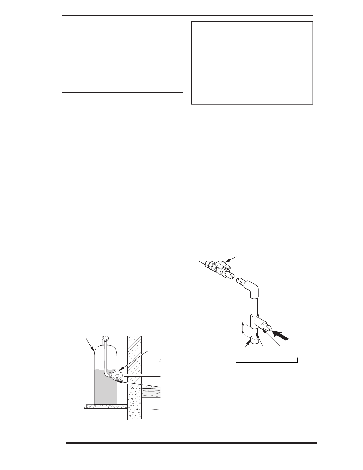
Figure 6 - Gas Connection
Sediment Trap
CSA Design-Certified
Equipment Shutoff Valve
With 1/8" NPT Tap*
3" Minimum
Cap Pipe Tee
Nipple Joint
CAUTION: Use only new,
black iron or steel pipe. Internally-tinned copper tubing may
be used in certain areas. Check
your local codes. Use pipe of
1/2" diameter or greater to allow
proper gas volume to fireplace.
If pipe is too small, undue loss
of volume will occur.
Installation must include an equipment shutoff
valve, union and plugged 1/8" NPT tap. Locate
NPT tap within reach for test gauge hook up.
NPT tap must be upstream from fireplace.
IMPORTANT:
Install equipment shutoff valv
e
in an accessible location. The equipment shutoff
valve is for turning on or shutting off the gas to
the appliance.
Check your building codes for any special requirements for locating equipment shutoff valve
to fireplaces.
Apply pipe joint sealant lightly to male NPT
threads. This will prevent excess sealant from
going into pipe. Excess sealant in pipe could result
in clogged fireplace valves. Never use sealant on
flare threads.
Propane/LP
Supply Tank
External
Regulator
Figure 5 - External Regulator
With Vent
Pointing Down
Vent
Pointing
Down
SHUTOFF VALVE
A CSA design-certified equipment shutoff valve
with
1/8" NPT tap is an acceptable alternative to
test gauge connection. Purchase the optional CSA
design-certified equipment shutoff valve from your
dealer.
For propane/LP units, the installer must supply
an external regulator. The external regulator will
reduce incoming gas pressure. You must reduce
incoming gas pressure to between 11 and 1
of water. If you do not reduce incoming gas pressure, heater regulator damage could occur. Install
external regulator with the vent pointing down
3 inches
Natural Gas
From Gas Meter
(5" W.C.** to 10.5"
W.C. Pressure)
Propane/LP
From External
Regulator
(11" W.C.** to 13"
W.C. Pressure)
Page 16
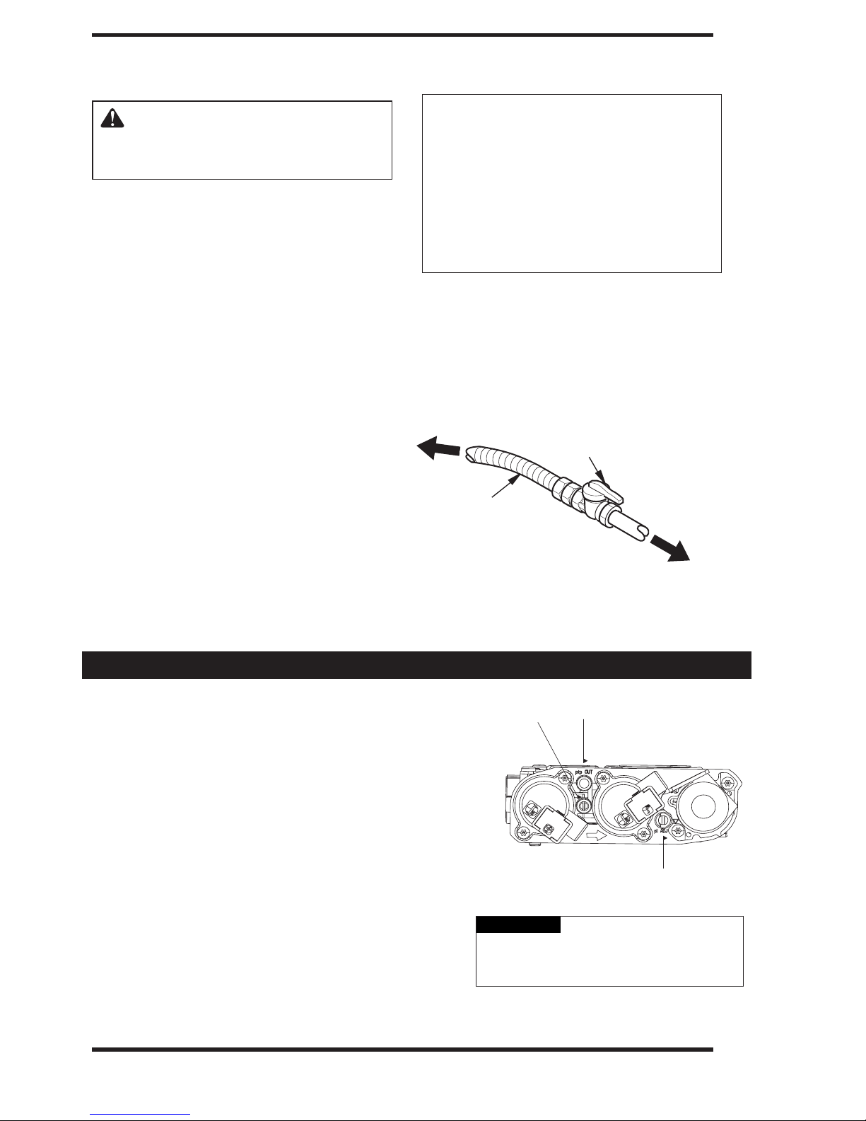
NOTICE: Most building codes
do not permit concealed gas
connections. A flexible gas line
is provided to allow accessibility
from the fireplace (see Figure 7).
The flexible gas supply line connection to the equipment shutoff
valve should be accessible.
INSTALLATION
Continued
Figure 7 - Attaching Flexible Gas Lines
Together
Flexible Gas Line
from Fireplace
Gas Regulator
To Fireplace
Gas Regulator
Equipment
Shutoff Valve
Provided by
Installer
Propane/LP
To External
Regulator
Natural Gas
To Gas Meter
WARNING: Use pipe joint
sealant that is resistant to liquid
petroleum (LP) gas.
We recommend that you install a sediment trap in
supply line as shown in Figure 6, page 12. Locate
sediment trap where it is within reach for cleaning. Install in piping system between fuel supply
and fireplace. Locate sediment trap where trapped
matter is not likely to freeze. A sediment trap traps
moisture and contaminants. This keeps them from
going into fireplace gas controls. If sediment trap
is not installed or is installed wrong, fireplace may
not run properly.
CONNECTING FIREPLACE TO GAS
SUPPLY
1. Remove access panel.
2. Route gas line (provided by installer) from
equipment shutoff valve to fireplace. Route
flexible gas supply line through one of the
access holes.
3. Attach the flexible gas line to gas supply as
per Figure 7. Check tightness of flexible gas
line attached to gas regulator of fireplace and
check all gas connections for leaks ( see
Checking Gas Connections, page 16).
1. Check gas type. The gas supply must be the same as
stated on the appliance’s rating decal. If the gas supply
is different from the replace, STOP! Do not install the
appliance. Contact your dealer immediately.
2. To ease installation, a 30" (mm) ex line with manual
shut-off valve has been provided with on this appliance.
Install and attach
1
/2" gas line onto shut-off valve.
Do not use open flame to check for gas leaks.
WARNING
4.
CHECKING GAS PRESSURE
3. After completing gas line connection, purge air from
gas line and test all gas joints from the gas meter to the
replace for leaks. Use a solution of 50/50 water and
soap or a gas sniffer.
T
o check gas pressures at valve,
screw counter clockwise 2 or 3 turns and then
place tubing to pressure gauge over test point.
IMPORTANT: Turn unit to high. After taking
pressure reading, be sure and turn captured
screw clockwise firmly to reseal. Do not
overtorque. Check test points for gas leaks!
16
turn captured
Inlet Pressure Tap
Outlet Pressure Tap
Pilot Adjustment
Page 17
CHECKING GAS CONNECTIONS
WARNING: Test all gas piping and connections, internal
and external to unit, for leaks
after installing or servicing. Correct all leaks at once.
WARNING: Never use an
open flame to check for a leak.
Apply a noncorrosive leak
detection fluid to all joints.
Bubbles forming show a leak.
Correct all leaks at once.
CAUTION: Make sure external regulator has been installed
between propane/LP supply and
fireplace. See guidelines under
Connecting Fireplace to Gas
Supply.
PRESSURE TESTING GAS SUPPLY
PIPING SYSTEM
Test Pressures In Excess Of 1/2 PSIG
(3.5 kPa)
2. Cap off open end of gas pipe where equipment
shutoff valve was connected.
3. Pressurize supply piping system by either
opening propane/LP supply tank valve for
propane/LP gas or opening main gas valve
located on or near gas meter for natural gas
or using compressed air.
4. Check all joints of gas supply piping system.
Apply noncorrosive leak detection fluid to all
joints. Bubbles forming show a leak.
5. Correct all leaks at once.
6. Reconnect fireplace and equipment shutoff
valve to gas supply. Check reconnected fittings
for leaks.
INSTALLATION
Continued
Figure 8 - Equipment Shutoff Valve
Open
Closed
Equipment
Shutoff Valve
2. Pressurize supply piping system by either
opening propane/LP supply tank valve for
propane/LP gas or opening main gas valve
located on or near gas meter for natural gas
or using compressed air.
3. Check all joints from gas meter to equipment
shutoff valve for natural gas or propane/LP
supply to equipment shutoff valve for propane/
LP . Apply noncorrosive leak detection fluid
to all joints. Bubbles forming shows a leak.
4. Correct all leaks at once.
PRESSURE TESTING FIREPLACE GAS
CONNECTIONS
1. Open equipment shutoff valve (see Figure 8).
2. Open main gas valve located on or near gas
meter for natural gas or open propane/LP
supply tank valve.
3.
Make
sure
control
knob
of
fireplace
is
in
the
OFF position.
show a leak.
5.
Correct all leaks at once.
6.
L
ight
fi
r
e
pla
c
e
(
s
e
e
O
pe
r
ating
F
ir
e
plac
e
,
pa
ge
7.
T
ur
n
of
f
fi
r
e
pl
a
c
e
(
s
e
e
T
o
Tur
n
O
f
f
G
as
t
o
Applianc
e
).
Test Pressures Equal To or Less Than
1/2 PSIG (3.5 kPa)
IMPORTANT: The appliance must be isolated
from the gas supply piping system by closing
its equipment shutoff valve during any
pressure testing of the gas supply piping
system at test pressures equal to or less than
1/2 psi (3.5 kPa).
1. Clos e e q ui p m e n t s h ut o f f v a l v e (see Figure 8).
1. IMPORTANT: The appliance and its
appliance
disconnected
system
that system at test pressures in
1/2 psi
main gas valve must be
from the gas supply piping
during any pressure testing of
excess of
(3.5 kPa).
4. Check all joints from equipment shutoff valve
to gas control valve . Apply noncorrosive leak
detection fluid to all joints. Bubbles forming
1
9
)
.
C
h
e
c
k
a
l
l
o
t
h
e
r
i
n
t
e
r
n
a
l
CAUTION: Verify proper operation
after servicing.
j
o
i
n
t
s
f
o
r
l
e
a
k
s
.
17
Page 18
18
Continued
INSTALLATION
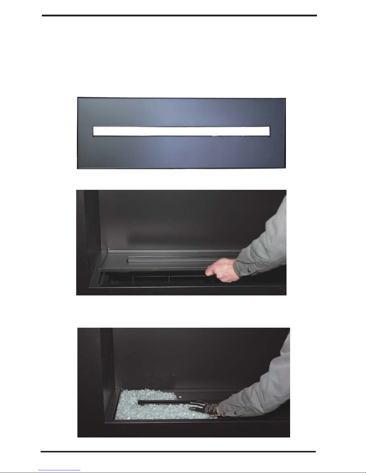
OPTIONAL MEDIA TRAY PLACEMENT
1.
Locate optional
media tray
2.
Place media tray on the support b rackets as sho
3
Fill the tray with
.
media supplied. Do not place media on burner or
block air flow between burner and tray
wn
Page 19

OPERATING FIREPLACE
OPERATING INSTRUCTIONS
FOR YOUR SAFETY
READ BEFORE
WARNING:Ifyou do not follow these
instructions exactly, a fire or explosion may
result causing property damage, personal
injury or loss of life.
A. This appliance is equipped with an ignition device
which automatically lights the pilot. Do Not try to
light the pilot by hand.
B. BEFORE LIGHTING:smell all around the appli-
ance area for gas. Be sure to smell next to the floor
because some gas is heavier than air and will settle
on the floor.
WHAT TO DO IF YOU SMELL GAS
• Do not try to light any appliance.
• Do not touch any electric switch; do not
use any phone in your building.
• Immediately call your gas supplier from a neighbor's phone. Follow the gas supplier's instruc-
tions.
•
If you cannot reach your gas supplier, call the fire
department.
C. Main gas valve in this appliance is not serviceable
and does not have any control knobs or switches to
operate. Do not remove heat shields covering the
valve and electronic devices; do not try to repair or
modify the valve as it may result in a fire or explo-
sion. Call a qualified service technician if you have
any safety concerns.
D. Do not use this appliance if any part has been under
water. Immediately call a qualified service techni-
cian to inspect the appliance and to replace any part
of the control system and any gas control which has
been under water.
LIGHTING
6
. Set remote receiver switch to OFF position.
Figure 9awRemote Receiver Switch in OFF Position
7
. Wait five (5) minutes to clear out any gas. Then
smell for gas, including near the floor. If you smell
gas, STOP! Follow "B" in the safety information.
If you don't smell gas, go to the next step.
Note: Before applying any power supply to the DFC
board, please verify that the electrical connections
areinaccordance to
8
. Plug supplied DC adapter into 110V power outlet.
. Connect the wire to the DC input plug at the unit.
:
9
1
0
. Locate remote receiver either inside the unit (see
illustrated parts list), or mounted in adjacent wall.
Make sure that the remote receiver switch is in
"REMOTE" (middle) position.
Fiqure 9b - Remote Receiver Switch in REMOTE
Position
1. Replace access panel (i.e
1
Wiring Diagram on page 29
inner cover or optional
.
media tray).
Initializing the System for the First Time
1.
Set the remote receiver switch to the OFF position.
OPERATING
INSTRUCTIONS
1. STOP! Read the safety information, starting on page
2. Remove media tray from the appliance (see Illustrated
parts list),
3. Turn off all electric power to the appliance. Unplug
DC adapter from the power outlet.
4. Do not attempt to light the pilot by hand.
5. Lift and remove heat shield covering electronic com-
5
. Turn main shutoff valve counterclockwise
ponents inside of the unit (see illustrated parts list).
to ON position.
2,
Figure 9c - Remote Receiver Switch in OFF Position
2.
Make sure that fresh set of
the battery holder and verify the polarity indicated on
the battery holder.
holder to the DFC's main wir ing harness.
AA batteries
If necessary, c
are installed
onnect the battery
into
11
19
Page 20
OPERATING INSTRUCTIONS
remain ON.
Manually
Note: If pilot does not stay lit, contact a qualified
1.
Slide the remote receiver switch to the ON position.
service person or gas supplier for repairs.
This will allow the main burner to ignite.
Manually
1. Slide the remote receiver switch to the OFF position.
This will turn off the main burner.
Turning ON the Appliance
Turning OFF the Appliance
Figure 9d - Remote Receiver Switch in ON Position
Figure 9d- Remote Receiver Switch in OFF Position
CAUTION: Do not try to adjust heating
levels by using the equipment shutoff
valve.
WARNING: Make sure the remote receiver
switch is in the OFF position when you are away
from home for long periods of time. Heater may
come on automatically with remote receiver
switch in the "REMOTE" position.
TO TURN OFF GAS
TO APPLIANCE
1. Tum off all electric power to the appliance if service
is to be performed. Unplug DC adapter from the
power outlet.
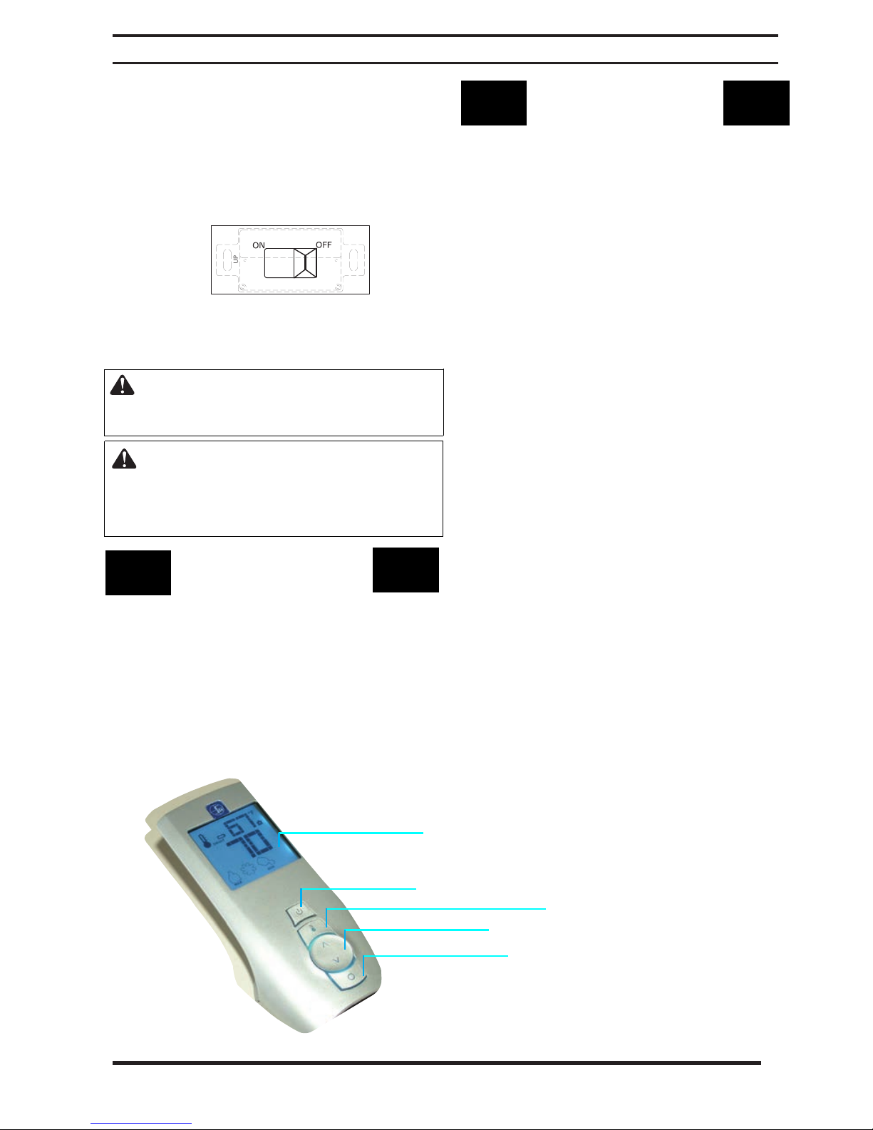
REMOTE CONTROL
OPERATION
Proflame G-Fire System Operation
Initializing the System for the First Time
1. Install the
Note the polarity of the batteries and insert into the
battery bay as indicated on the battery covel'
2. Place the 3-posilion slider switchinthe REMOTE
position.
3. Insert the end of a paper clip into the hole marked
PRG on the receiver front cover. The receiver will
beep three times to indicate that it is ready to synchronize with a transmitter.
4. Install the 3 AAA batteries in the transmitter battery
bay located on the base of the transmitter.
5.
Press
will beep four times to indicate the
command is accepted. The system is
ized.
Temperature Indication Display
1.
With the system in the OFF position, press the
THERMOSTAT key and the MODE key at the same
time.
2. Look at the LCD screen
that
temperature
4
AA batteries into the receiver batter bay.
(+/-).
the ON
a °C or°F is visible to the right of the room
button on the transmitter. The receiver
transmltters
now
on
the transmitter to verify
display.
initial-
2. If necessary, remove access panel from the appliance
to access manual shutoff valve on gas line.
3. Turn the gas control manual valve clockwise
to the full OFF position.
4. If necessary, replace media tray or access panel
Blue LCD display
ON/OFF Key
20
THERMOSTAT Key
W
UP/DO
N Arrow
Key MODE Key
Page 21
21
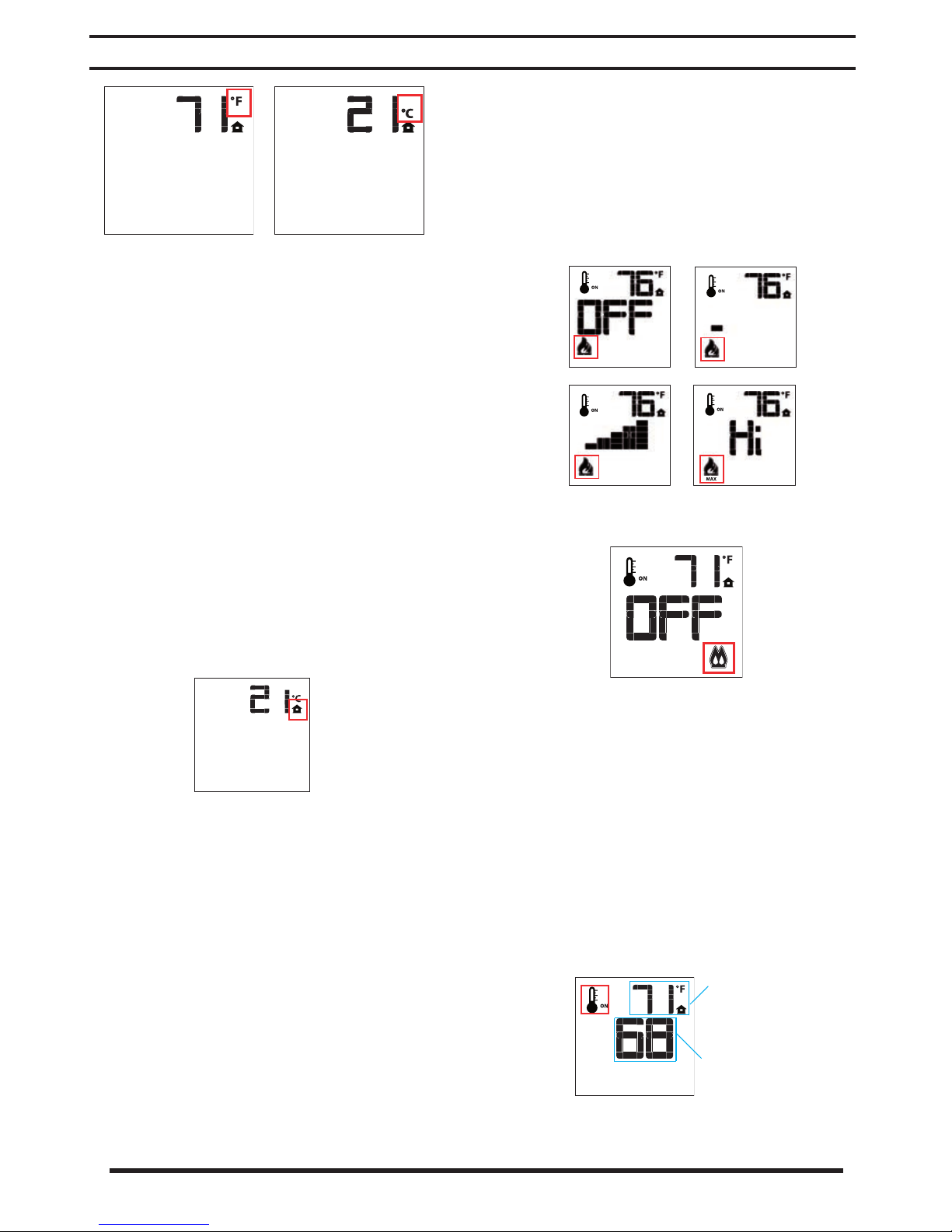
T
Figure 10 - Remote Control Display in Farenheit and
Celsius
Turning ON the Appliance
1. Press the ON/OFF button on the transmitter. The
transmitter screen will display all active icons. The
receiver will command the DFC board to start the
ignition process, Once the pilot flame is lit, the DFC
ard
will
bo
burner will ignite. A single "beep" from the receiver
will confirm the command.
open the main valve outlet and the main
OPERATING INSTRUCTIONS
2. Press the up-arrow key to increase the flame
hcight.
Note:
system is ON but the flame is OF
come on in the high position, A single "beep" from
If you press the up-arrow key while the remote
F, the flame will
the receiver
will confirm the command.
Flame Levell
Turning OFF the Appliance
1. Press the ON/OF
transmitter LC
temperature and icon (see Figure 11). The receiver
disconnects and
turn off the burner.
A single
command.
Figure 11 - Remote Control Displaying Room
Temperature
"beep" from the receiver will confirm the
F button
D display will only show the room
will
011
the transmitter, The
command the DFC board to
Flame Level 5
Figure 12
Figure 13 - Remote Control Displaying Split Flow Mode
- Remote Control Displaying Flame Levels
Room Thermostat
The remote control can operate as a room thermostat.
The thermostat can be set to a desired temperature to
control the comfort level in the room.
1.
To activate this function, press the Thermostat key.
The LCD display on the transmitter
show that the room thermostat is ON and the set
temperature is now displayed (see Figure 14).
2. Adjust the set temperature by pressing the up or
down-arrow keys until the desired set temperature
is displayed on the LCD screen (see Figure 14).
Flame
Level Max.
(Transmitter Operation)
will
change to
Flame Height Control
Proflame GTM
These units have six flame levels (see Figure 12).
1.
With the system ON and the flame level at maximum
height, press the down-arrow key once to reduce the
flame height by one step. Continue pressing downarrow key until flame is turned OFF.
Room
Temperature
Set
Temperature
Figure 14 - Remote Control Displaying Room
Temperature and Set Temperature
Page 22

22
Pilot IPI / CPI
switch
Position of the
receiver slider switch
Command reference
name
Commanded Fireplace
State
Opened, IPI
“OFF”
“REMOTE”
and “OFF received”
Turn-OFF Flames OFF
Opened, IPI
“ON”
“REMOTE”
and “ON received”
Turn-ON
Pilot + Main burner
flames ON
Closed, CPI
“OFF”
“REMOTE”
and “OFF received”
Pilot-ON Pilot flame ON
Closed, CPI
“ON”
“REMOTE”
and “ON received”
Turn-ON
Pilot + Main burner
flames ON
T
OPERATING INSTRUCTIONS
Smart Thermostat
(Transmitter Operation" Proflame GTM )
The Smart Thermostat function adjusts the flame height
in accordance to the difference between the set point
temperature and the actual room temperature. As the
room temperature gets closer to the set point, the Smart
Function
1. To activate this function, press the Thermostat key
2. To adjust the set temperature, press the up or
Figure
Thermostat Function
Key Lock
This function will lock the keys to avoid unsupervised
operation.
1.
2. To deactivate this function, press the MODE and UP
will
modulate the flame down.
until the word "SMART" appears to the right of the
temperature bulb on the LCD screen (see Figure
15).
down-arrow keys until the desired set temperature
is displayed on the LCD screen.
15-
Remote Control Displaying Smart
To activate this function, press the MODE and UP
keys at the same time. A lock icon
will
appear on the
LCD screen (sec Figure 16).
keys at the same time. The lock icon
will
disappear
from the LCD screen.
Low Battery Power Detection
Receiver
The life span of the receiver batteries depends upon
various factors: battery quality, Humber of appliance
nitions, number of thermostat set point changes, etc.
'Vhen the receiver batteries are low, no "beep" will
sound from the receiver when a transmitter command
is sent. Replace batteries when this happens,
ig-
Transmitter
The life span of the transmitter batteries depends upon
various factors: battery quality, number of appliance ignitions, number of thermostat set point changes, etc.
When the transmitter batteries arc low, an icon will
appeal' on the LCD display (see Figure 17), Replace
batteries when this icon appears.
Figure
Manual
If the receiver or transmitter batteries are low or de-
pleted, the appliance can still be turned on manually.
1.
17-
Remote Control Displaying Low Battery
Override
Move the
position. This
receivers
will
three-position slider to the
ON
bypass the remote control feature
of the system and the appliance main burner will
turn on.
Figure
16 -
Remote Control Displaying Key Lock Mode
Command Definitions
Page 23

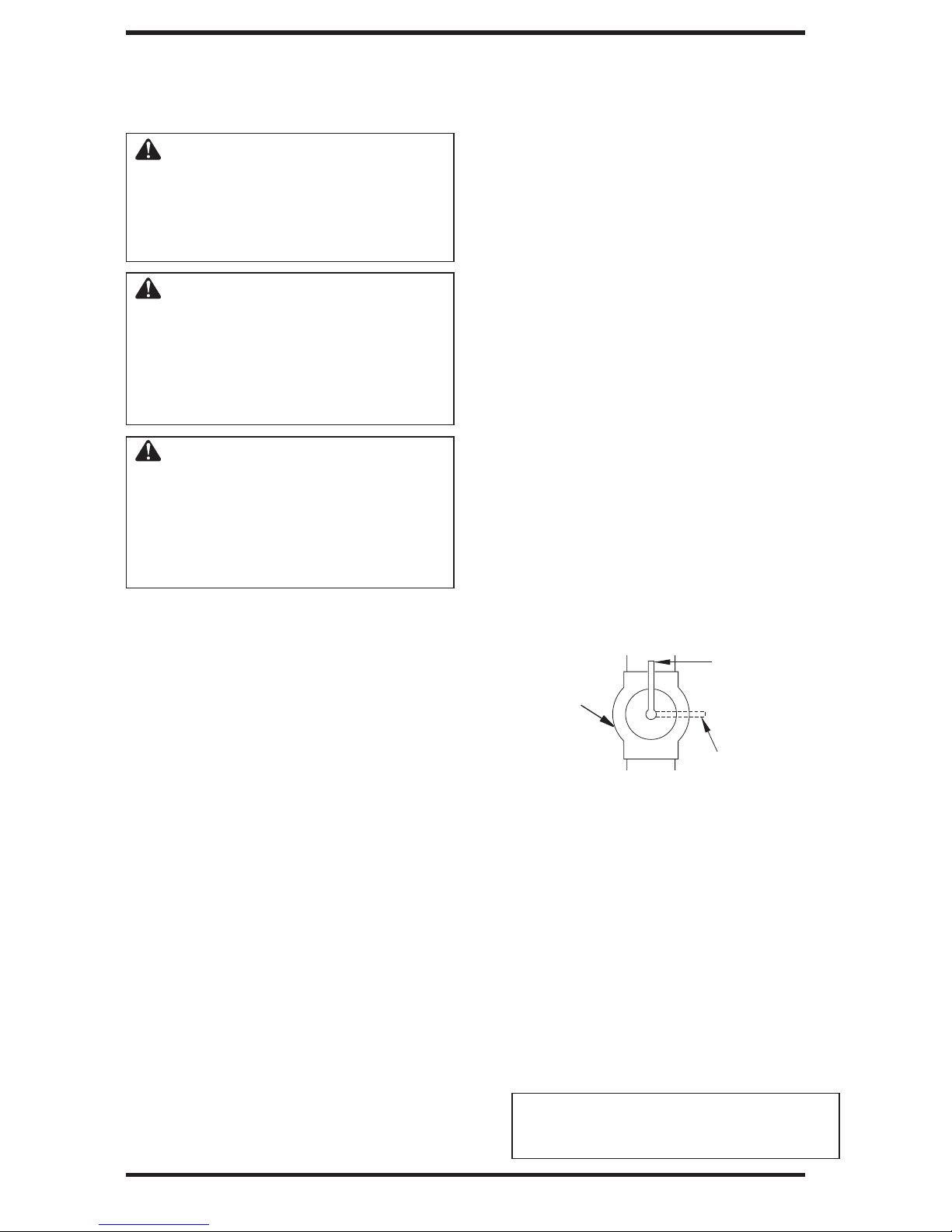
INSPECTING BURNERS
Check pilot flame pattern and burner flame patterns often.
PILOT FLAME PATTERN
.
MAIN BURNER
Periodically inspect all burner flame holes with the
heater running.
Some burner flame holes may become blocked
by debris or rust, with no flame present. If so, turn
off heater and let cool. Remove blockage. Blocked
burner flame holes may create soot.
FRONT BURNER FLAME PATTERN
• turn fireplace off (see To Turn Off Gas to Ap-
plian
c
e).
CLEANING AND MAINTENANCE
Figure 17 shows a correct pilot flame
pattern. Figure 18 shows an incorrect
pilot flame pattern.
The incorrect pilot flame is not touching the
flame sensor. This will cause the flame sensor
to
cool. When the flame sensor cools, the
fireplace will shut down.
Figure 19 shows correct burner flame
pattern withpatern with yellow flame tips and blue
base. Figure 20 shows incorrect flame pattern. The
incorrect bur ner flame pattern shows lazy orange
flame.
I f b u r n e r fl a m e p a t t e r n i s
i n c o r r e c t , a s shown inF i g ur e
20:
Figure 17 - Correct Pilot Flame Pattern
Figure 1
If pilot flame pattern is incorrect, as shown in
Figure 18
• turn fireplace off (see To T
pliance, p
8 - Inorrect Pilot Flame Pattern
urn Off Gas to Ap-
20
age
Troubleshooting, page
•
see
Figure 19 - Correct Burner Flame Pattern
Figure
Pattern
20 - Incorrect Burner Flame
caused by port blockage
25
.
•
see Troubleshooting, page 25
Note: The correct pilot flame on natural gas units
will have a slight curve, but flame should be blue
and have no yellow or orange color.
.
23
Page 24

CLEANING AND
MAINTENANCE
WARNING: Turn off fireplace
and let cool before cleaning.
CAUTION: You must keep
control areas, burner and circulating air passageways of
fireplace clean. Inspect these
areas of fireplace before each
use. Have fireplace inspected
yearly by a qualified service
person. Fireplace may need
more frequent cleaning due to
excessive lint from carpeting,
bedding material, pet hair, etc.
WARNING: Failure to keep
the primary air opening of the
burner clean may result in soot-
ing and property damage.
BURNER INJECTOR HOLDER AND
PILOT AIR INLET HOLE
The primary air inlet holes allow the proper amount
of air to mix with the gas. This provides a clean
burning flame. Keep these holes clear of dust, dirt,
lint and pet hair. Clean these air inlet holes prior to
each heating season. Blocked air holes will create
soot. We recommend that you clean the unit every
three months during operation and have heater
inspected yearly by a qualified service person.
We also recommend that you keep the burner
tube and pilot assembly clean and free of dust and
dirt. To clean these parts we recommend using
compressed air no greater than 30 PSI. Your local
computer store, hardware store or home center
may carry compressed air in a can. You can use a
vacuum cleaner in the blow position. If using compressed air in a can, please follow the directions on
the can. If you donʼt follow directions on the can,
you could damage the pilot assembly.
1. Shut off the unit, including the pilot. Allow
the unit to cool for at least thirty minutes.
4. Check the injector holder located at the end
of the burner tube again. Remove any large
particles of dust, dirt, lint or pet hair with a
soft cloth or vacuum cleaner nozzle.
5. Blow air into the primary air holes on the
injector holder.
6. In case any large clumps of dust have now been
pushed into the burner repeat steps 3 and 4.
Clean the pilot assembly also. A yellow tip on the
pilot flame indicates dust and dirt in the pilot assembly
two inches from where the pilot flame comes out
of the pilot
With the unit off, lightly blow air through the air
inlet hole. You may blow through a drinking straw
if compressed air is not available.
. There is a small pilot air inlet hole about
assembly
Figure 22).
(see
2. Inspect burner, pilot and primary air inlet
holes on injector holder for dust and dirt (see
Figure 21 ) .
Blow air through the ports and holes in
3.
the burner.
________
Ports
Burner
________
Tube
Primary Air Hole(s)
Orifice
Figure 21 - Injector Holder On Outlet
________
________
Burner Tube
________
Primary
_
Air Inlet
Holes
Figure
22 - Pilot Inlet Air Hole
24
Page 25

TROUBLESHOOTING
WARNING: Turn off heater and let cool before servicing. Only a
qualified service person should service and repair heater.
CAUTION: Never use a wire, needle or similar object to clean
ODS/pilot. This can damage ODS/pilot unit.
Note: All troubleshooting items are listed in order of operation.
OBSERVED PROBLEM POSSIBLE CAUSE REMEDY
When remote button is pressed,
there is no spark at ODS/pilot
When remote button is pressed,
there is spark at ODS/pilot but
no ignition
Ignitor electrodenot con-
I.
nected to ignitor cable
Ignitor cable pinched or
2.
wet
Broken ignitor cable
3.
4. Bad ignitor
Ignitor electrode broken
5.
6. Ignitor electrode positioned
wrong
7. Low batteries 7. Replace batteries in remote control
and receiver, re-program the receiver.
Gas
1.
supply turned off or
equipment
closed
shutoff
valve
2. Depleted gas supply
3. Defective DFC module. 3. Replace DFC module.
4. ODS/pilot is clogged
1.
Reconnect ignitor cable
2. Free ignitor cable if pinched
by any metal or tubing.
Keep ignitor cable dry
3. Replace ignitor cable
4. Call for service
5. Replace pilot assembly
6. Replace pilot assembly
1.
2 .
4.
n gas supply or open
Turn o
equipment
Contact local propanc/LP
gas company
Clean ODS/pilot (see
shutoff
valve
Cleaning and Maintenance,
24
)
or replace ODS/
5. Gas regulator setting is not
page
pilot assembly
5.
Replace gas control
correct
25
Page 26

TROUBLESHOOTING
OBSERVED PROBLEM POSSIBLE CAUSE REMEDY
Continued
ODS/pilot lights but flame
goes
out
Equipment shutoff valve 1. Fully open equipment shut-
1
.
not fully open
2. Pilotflame not touching 2. A) Contact local propane/LP
f
lame sensor, which allows flame sensor to cool,
causing pilot flame to go B) Clean ODS/pilot (see
out. This problem could be Cleaning and Maintenance,
caused by one or both of
the following: pilot assembly
A) Low gas pressure
B) Dirty or partially clogged
ODS/pilot
3.
Flame sensor connection
loose at control valve then tighten
4.
Flame sensor damaged
Control valve damaged 5. Replace control valve
5.
6.
Safety interlock system has 6.
been triggered
7. Defective DFC module. 7. Replace DFC module.
off valve
gas company
page24) or replace
Hand tighten until snug,
3.
1/4
turn more
Replace pilot assembly
4.
Wait one minute for safety
interlock system to reset.
Repeat ignition operation.
ODSI
Burner does not light after
ODS/pi lot is
Delayed ignition burner
low
lit
Inlet gas pressure is too
1
.
low
2. Burner orifice clogged 2. Clean burner (see Cleaning and
3. Burners will not come on 3.Replace battery in transmit-
in remote position
4 .
Wire disconnected from 4. Reconnect wire (see Wiring
gas control
5. Defective DFC module. 5. Replace DFC module.
Manifold pressure is too
1
.
2. Burner orifice clogged
1.
Contact local natural or
propanc/LP gas supplier.
Maintenance,
or replace burner orifice
ter and receiver
Diag
ram
,
page 29)
Contact local natural or
1.
propane/LP gas company
2.
Clean
burner
and Maintenance, page
or replace burner orifice
(see Cleaning
page
24
24
)
)
26
Page 27

TROUBLESHOOTING
Continued
OBSERVED PROBLEM POSSIBLE CAUSE REMEDY
Burner backfiring during
combustion damaged
Slight smoke or odor during
initial operation
1. Burner orifice is clogged or
2.
Damaged burner
Gas regulator defective 3. Replace gas regulator
3.
Residues from manufactur-
1.
ing processes few hours of operation
2.
Not enough air
3. Gas regulator defective
Moisture/condensation noticed on windows ventilation air andVcntilation require-
Heater produces a whistling 1.
noise when burner is lit
1. Not enough combustion/
Advance control to
position when burner
is cold a minute
2.
Air in gas line
3. Air passageways
blocked
4. Dirty or partially clogged 4. Clean burner (see Cleaning
burner orifice and Maintenance, page
HI
on
heater 3. Observe minimum installa-
Clean burner (see Cleaning
I.
a
nd Maintenance, page24)
or replace burner orifice
2.
Replace damaged burner
1.
Problem will stop after a
2.
Check burner for dirt and
If f
debris.
burner (see Cleaning and
Maintenance, page
Replace gas control
3.
Refer to Airfor Combustion
I.
ments (page 4)
I.
Turn
position and let warm up for
2.
Operate burners until air is
removed from line. Have
gas line checked by local
natural or propane/LP gas
company
lion clearances (see page 8)
or replace burner orifice
ound, clean
remote
control knob to LO
24
)
24
)
White powder residue forming within burner box or 011 furniture polish, wax, car- furniture polish, wax, cleanadjacent walls or furniture
Remote does not function
1. When heated, vapors from 1.Turn heater off when using
pet cleaners, etc. turn into ers, or similar products
white powder residue
1. Remote is "locked"
2.
Batteries are not installed. 2. Replace batteries in receiver
Battery power is low and remote control, re-program
receiver.
Sec instructions on page22,
1.
Key
Lock
27
Page 28

OBSERVED PROBLEM POSSIBLE CAUSE REMEDY
TROUBLESHOOTING
Continued
WARNING: If you smell gas
• Shut off gas supply.
• Do not try to light any appliance.
•
Do not touch any electrical switch; do not use any phone in your building.
• Immediately call your gas supplier from a neighbor’s phone.
Follow the gas supplier’s instructions.
• If you cannot reach your gas supplier, call the fire department.
IMPORTANT: Operating fireplace where impurities in air exist may create odors. Cleaning supplies,
paint, paint remover, cigarette smoke, cements and glues, new carpet or textiles, etc., create fumes. These
fumes may mix with combustion air and create odors. These odors will disappear over time.
Fireplace produces a clicking/
ticking noise just after burners
are lit or shut off
Fireplace produces unwanted
odors
Fireplace shuts off in use
(ODS operates)
Metal expanding while
1.
heating or contracting most fireplaces.Ifn
while cooling
Fireplace burning vapors
1.
from paint, hair spray, room. Stop using odor cansglues, cleaners, chemicals, ing products while fireplace
new carpet, etc. (see
ORTANT
IMP
Low fuel supply (propane/ 2.
2.
LP gas only) LP gas only)
Gas leak. See Warning
3.
statement a
1.
Not enough fresh air is
available for ventilation
Low line pressure
2.
ODS/pilot is partially
3.
clogged Cleaning and Maintenance,
statement above)
bove.
This is common with
1.
excessive, contact qualified
service person
Open window and ventilate
1.
is funning
Re fill
supply tank (propane/
3. Locate and correct all leaks
(see Checking Gas Connec-
tions, page
1.
Open window and/or door
2.
Contact local natural or
propane/LP gas company
Clean ODS/pilot (see
3.
page
24
) .
14
)
oise
is
Gas odor even when control
knob is in OFF position
Gas odor during combustion
28
1.
Gas leak.
2,
Control valve or gas
trol defective control
1. Foreign matter between
control valve and burner remove foreign matter
2.
Gas leak. See Warning
statement at top
1.Locate and
con
-
2.Locate and correct all leaks
of page.
2.
Replace control valve or gas
Take apart gas tubing and
1.
corr
ect
all leaks.
(see Page 14)
Page 29
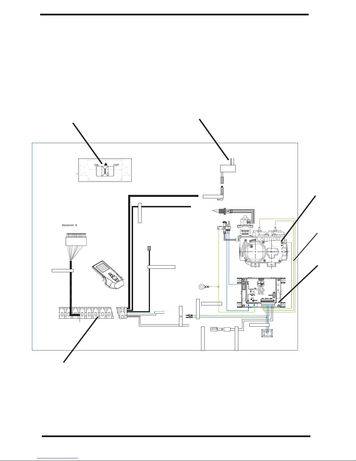
Proflame Wiring Diagram
This diagram shows replaceable SIT Proflame parts used in your fireplace
31
( please, refer to pages
1
1
7
8
).
120 Vac INPUT
7 Vdc STABILIZED
SUPPLY OUTPUT
Receiver 14
Pin Connector
RECEIVER
DC SUPPLY
MOTOR
Pilot
Orange
Green
11
SPLIT FLOW
Chassis
TH
TPTH
connection
GROUND
ON / OFF
DFC SUPPLY
1
6
885 PROFLAME
IPI/CPI
DC SUPPLY
4
20
19
21
29
Page 30

2
11
10
9
3
4
8
22
7
5
41
1
6
for references see page 31( )
13
20
19
ILLUSTRATED PARTS BREAKDOWN
21
17
30
Page 31
PARTS LIST
This list contains replaceable parts used in your firebox.
All replacement parts should be ordered from your installer or from Spark Modern Fires
at 1-8669-383-846
KEY PART NUMBER
NO. 58N 58P DESCRIPTION QTY.
1 W800004N W800004P BURNER ASSEMBLY 1
2 F200026 F200027 BURNER ORIFICE 1
3 C100036 C100036 TS-12 BURNER FLEX CONNECTOR 1
4
5
6
7
C200001 C200002 MAIN GAS VALVE
H200013 H200005 VENT-FREE PILOT ASSEMBLY 1
C100039 C100039 PILOT FLEX TUBE 1
F200023 F200023 PILOT MOUNT BRACKET 1
8 H100005 H100005 3/8"NPS X 5/16" COMP. 90 DEG. FITTING 1
9 C100084 C100084 3/8"NPS X 3/8" FLARE 90 DEG. FITTING 1
10 C100009 C100009 3/8" X 24" FLEX. CONNECTOR 1
11 F200066 F200066 SUPPLIED SHUTOFF VALVE 1
12 W800006 W800006 MEDIA TRAY (OPTIONAL, not shown) 1
13 W800005 W800005 INNER COVER 1
14 H200014 H200014 SPARK WIRE (V-F PILOT) 1
15 C100020 C100020 DUPLEX POWER OUTLET (not shown) 1
16 H200001 H200001 PROFLAME GTM TRANSMITTER 1
17 H200010 H200010 PROFLAME GTM RECEIVER 1
18 H100140 H100140 7V AC/DC POWER ADAPTER 1
19 H100142 H100142 SIT DFC CONTROL BOARD 1
20 H200012 H200012 VALVE WIRE HARNESS 1
21 22 H200011 H200011 GTM RECEIVER WIRE HARNESS 1
22 H200006 H200006 FLAME SENSOR WIRE (V-F PILOT) 1
24
23 F200022 F200022 VALVE MOUNT BRACKET 1
25
or on-line at www.sparkfires.com
W/STEPPER MOTOR
1
ACCESSORIES AVAILABLE (NOT SHOWN)
XXXXXXX XXXXXXX VARIOUS MEDIA FOR TRAY 1
31
Page 32

LIMITED LIFETIME WARRANTY
The following components are warranted for life to the original owner, subject to proof of purchase: Firebox,
Combustion Chamber, and Steel Burner.
BASIC WARRANTY
Spark Modern Fires warrants the components and materials in your gas appliance to be free from manufacturing
and material defects for a period of two years from date of installation. After installation, if any of the components manufactured by Spark Modern Fires in the appliance are found to be defective in materials or workmanship, Spark Modern Fires will, at its option, replace or repair the defective components at no charge to the original owner. Spark Modern Fires will also pay for reaonable labor costincurred in replacing or repairing such components for a period of two years from date of installation. Any products presented for warranty repair must be
accompanied by a dated proof of purchase.
This Limited Lifetime Warranty will be void if the appliance is not installed by a qualified installer in accord-
ance with installation instructions. The Limited Lifetime Warranty will also be void if the appliance is not operated and maintained according to the operating instructions supplied with the appliance, and does not extend to (1)
firebox/burner assembly damaged by accident, neglet, misuse, abuse, alterations, negligence of others, including the installation thereof by unqualified installers, (2) the costs of removal, reinstallation or transportation of
defective parts on the appliance, or (3) indentical or consequential damage. All service work must be performed
by an authorized service representative.
This warranty is expressly in lieu of other warranties, express or implied, including the warranty of merchantability of fitness for purpose and of all other obligations or liabilities. Spark Modern Fires does not assume for it
any other obligations or liabilities in connection with sale or use of the appliance. It states that do not allow limitations on how long an implied warranty lasts, or do not allow exclusion of indirect damage, those limitations of
exclusions may not apply to you. You may also have additional right not covered in the Limited Lifetime War-
ranty. Spark Modern Fires reserves the right to investigate any and all the claims against this Warranty and decide upon method of settlement. For information about this warranty contact:
WARRANTY INFORMATION
KEEP THIS FOR WARRANTY
Model
Serial No.
Date Purchased
Always specify model and serial numbers when communicating with the factory.
Spark Modern Fires
53 Chestnut Woods Rd.
Redding, CT 06896
U.S.A.
REV. 8/2015
 Loading...