

SparcLAN CAS-700W User Manual

Wireless Internet Camera
User’s Guide
Version 1.0

TABLE OF CONTENTS
ABOUT T H IS GUI D E ...........................................................4
1. INTRODUCTION..............................................................5
EATURES AND BENEFITS .........................................................6
F
U
NPACKING THE PACKAGE .......................................................8
S
YSTEM REQUIREMENT.............................................................9
P
HYSICAL DESCRIPTION ..........................................................10
2. HARDWARE INSTALLATION.................................15
A
TTACHING THE CAMERA TO THE STAND
C
ONNECTING THE ETHERNET CABLE ......................................16
A
TTACHING THE POWER SUPPLY ............................................16
...............................15
3. SEC U R I TY.........................................................................17
4. APP L I CATION O F THE CAM E R A .......................18
PPLICATIONS .........................................................................19
A
A
PPLICATION DIAGRAMS OF THE CAMERA.............................20
2

5. USI N G THE CAM E R A .................................................22
EB CONFIGURATION UTILITY...............................................22
W
S
YSTEM ADMINISTRATION ......................................................24
V
IEW VIDEO – ACTIVEX MODE ..............................................42
V
IEW IMAGE – JAVA MODE.....................................................43
6. IPV I E W PRO ....................................................................45
NSTALLATION.........................................................................45
I
G
ETTING STARTED ..................................................................49
U
SING IPVIEW PRO .................................................................52
C
ONFIGURING THE SYSTEM.....................................................57
7. APP E NDIX.........................................................................72
A FREQUENTLY ASKED QUESTIONS........................................72
B PING YOUR IP ADDRESS .....................................................75
C TROUBLE SHOOTING ............................................................76
D TIME ZONE TABLE ...............................................................80
E XPLUG CONTROL INSTALLATION.........................................82
F ADJUST INTERNET CAMERA FOCUS .....................................86
G I/O TERMINAL APPLICATION ...............................................87
H SPECIFICATION.....................................................................89
I GLOSSARY OF TERMS............................................................92
3

ABOUT THIS GUIDE
This manual provides instructions and illustrations on how to use
your Internet Camera, includes:
z Chapter 1, Introduction, provides the general information
on the camera.
z Chapter 2, Hardware Installation, describes the hardware
installation procedure for the camera.
z Chapter 3, Security, explains the security feature of the
camera.
z Chapter 4, Application of the Camera, provides the
illustrations of the camera’s applications.
z Chapter 5, Using the Camera, guides you through the
configuration using the web browser.
z Chapter 6, IPView Pro, helps you to install and use the
software.
z Chapter 7, Appendix.
Please note that the illustrations or setting values in this manual
are FOR YOUR REFERENCE ONLY. The actual settings and
values depend on your system and network. If you are not sure
about the respective information, please ask your network
administrator or MIS staff for help.
4

1
INTRODUCTION
Thank you for purchasing the Wireless Internet Camera, a camera
device that can be connected directly to an Ethernet or Fast
Ethernet network and also supported by the wireless transmission
based on the IEEE 802.11g standard. Compared to the
conventional PC Camera, the Wireless Internet Camera features a
built-in CPU and web-based solutions that can provide a costeffective solution to transmit real-time high-quality video images
and sounds for monitoring. The Wireless Internet Camera can be
managed remotely, accessed and controlled from any
PC/Notebook over the Intranet or Internet via a web browser.
The simple installation procedures and web-based interface allow
you to integrate it into your network easily. With comprehensive
applications supported, the Wireless Internet Camera is your best
solution for remote monitor, high quality, and high performance
video images.
5

Features and Benefits
Simple To Use
The Wireless Internet Camera is a standalone system with built-in
CPU requiring no special hardware or software such as PC frame
grabber cards. The Wireless Internet Camera supports both
ActiveX mode (for Internet Explorer users) and Java mode (for
Internet Explorer and Netscape Navigator users). Therefore, all
that is required is a web browser software such as Internet
Explorer 5.0 or above or Netscape 6.0 or above. Just plug and
view the picture from your Wireless Internet Camera with a valid
IP Address.
Support Variety of Platforms
The Wireless Internet Camera supports TCP/IP networking,
SMTP e-mail, HTTP and other Internet related protocols, and can
be utilized in a mixed operating system environment such as
Windows, Unix, and Mac. It can be integrated easily into other
www/Intranet applications.
Web Configuration
Applying a standard web browser, the administrator can configure
and manage the Wireless Internet Camera directly from its own
web page via the Intranet or Internet. Up to 64 users name and
password are permitted with privilege setting controlled by the
administrator.
6

RS-485 Support
The pin 5 & 6 of the I/O connectors are used for RS-485 data
transmission. You can connect a special featured device (such as
an external camera stand with rotation function) to meet you
needs. When the external device is connected, you could
configure the settings and control the device from the Trigger
window of Web Configuration Utility.
Remote Utility
The powerful IPView Pro application assigns the administrator
with a pre-defined user ID and password, allowing the
administrator to modify the Wireless Internet Camera settings
from the remote site via Intranet or Internet. When new firmware
is available, you can also upgrade remotely over the network for
added convenience. Users are also allowed to monitor the image,
and take snapshots.
Broad Range of Applications
With today’s high-speed Internet services, the Wireless Internet
Camera can provide the ideal solution for live video images over
the Intranet and Internet for remote monitoring. The Wireless
Internet Camera allows remote access from a web browser for
live image viewing and allows administrator to manage and
control the Wireless Internet Camera anywhere and any time in
the world. Apply the Wireless Internet Camera to monitor
various objects and places such as homes, offices, banks,
hospitals, child-care centers, amusement parks and other varieties
of industrial and public monitoring. The Wireless Internet
Camera can also be used for intruder detection; in addition, it can
capture still images for archiving and many more applications.
7

Unpacking the Package
Unpack the package and check all the items carefully. In addition
to this User’s Guide, be certain that you have:
One Wireless Internet Camera (with external antenna)
One Installation CD-ROM
One Quick Installation Guide
One AC power adapter suitable for your country’s electric
power
One Camera Stand
One RJ-45 Ethernet Cable
If any item contained is damaged or missing, please contact your
local dealer immediately. Also, keep the box and packing
materials in case you need to ship the unit in the future.
8

System Requirement
Networking
Local Area Network:
10Base-T Ethernet or 100Base-TX Fast Ethernet.
Wireless Local Area Network:
IEEE 802.11g Wireless LAN.
Accessing the Camera
For Web Browser Users
Operating System: Microsoft® Windows® 98SE/ME/
2000/XP
CPU: Intel Celeron 1.1GHz or above (Intel Pentium 4 is
preferred)
Memory Size: 128MB or above
Resolution: 800x600 or above
Microsoft® Internet Explorer 5.0 or above
For IPView Pro Application Users
Operating System: Microsoft® Windows® 98SE/ME/
2000/XP.
CPU: Intel Celeron 1.1GHz or above (Intel Pentium 4 is
preferred)
Memory Size: 128 MB or above
Resolution: 800x600 or above
9
Physical Description
This section describes the externally visible features of the
Wireless Internet Camera.
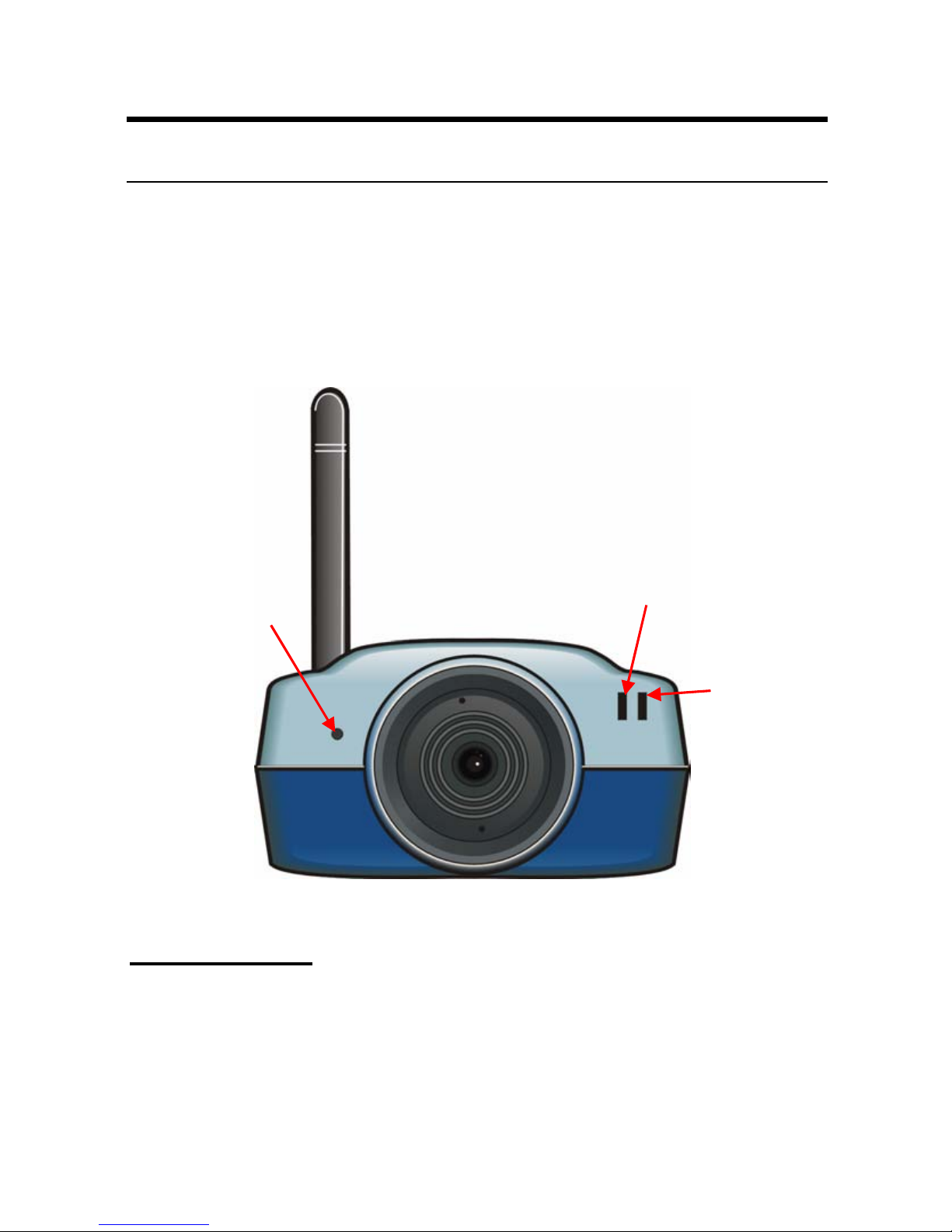
Front Panel
1. Power LED
3. Internal MIC
2. Link LED
1. Power LED
The Power LED is positioned on the right side of the Wireless
Internet Camera’s lens while facing the Wireless Internet Camera.
A steady BLUE light confirms that the Wireless Internet Camera
is powered on.
10

2. Link LED
The Link LED is positioned on the right side of the Wireless
Internet Camera’s lens while facing the Wireless Internet Camera.
It is located right of the Power LED
A steady ORANGE light confirms that the camera has good
connection to LAN connectivity.
Dependent on the data traffic the LED will begin to flash to
indicate that the Wireless Internet Camera is receiving/sending
data from/to the network.
3. Internal MIC
The built-in omni-directional microphone allows the camera to
receive sound and voice.
11

Rear Panel
r
1. External Antenna
3. Reset Button
5. DC Power
Connecto
2. Network Cable Connector
4. I/O Connector
1. External Antenna
The rotatable external antenna allows you to adjust its position to
obtain the maximum signal.
2. Network Cable Connector
The Wireless Internet Camera’s rear panel features an RJ-45
connector for connections to 10Base-T Ethernet cabling or
100Base-TX Fast Ethernet cabling (which should be Category 5
twisted-pair cable). The port supports the N-Way protocol and
“Auto-MDIX” function, allowing the Wireless Internet Camera to
automatically detect or negotiate the transmission speed of the
network.
12

3. Reset Button
Reset will be initiated when the reset button is pressed once, and
Power LED begins to flash.
Factory Reset will be initiated when the reset button is pressed
continuously for three seconds or when Power LED begins to
light up. Release the reset button and the Power LED will begin
to flash, indicating the Wireless Internet Camera is changing to
factory reset. When factory reset is completed, the Wireless
Internet Camera will be set to default on channel 11 and SSID is
set as “NULL String” (This default setting will let the Wireless
Internet Camera connect to ANY access point on the
infrastructure network). The IP address will also return to the
default setting as 192.168.0.30.
4. I/O Connector
The camera provides the I/O connectors on the rear panel (pin 1/2
are for input, pin 3/4 are for output, pin 5/6 are for RS-485),
which provide the physical interface to send and receive digital
signals to a variety of external alarm devices.
5. DC Power Connector
The DC power input connector is located on the Wireless Internet
Camera’s rear panel, and is labeled DC5V with a single jack
socket to supply power to the Wireless Internet Camera. Power
will be generated when the power supply is connected to a wall
outlet.
13
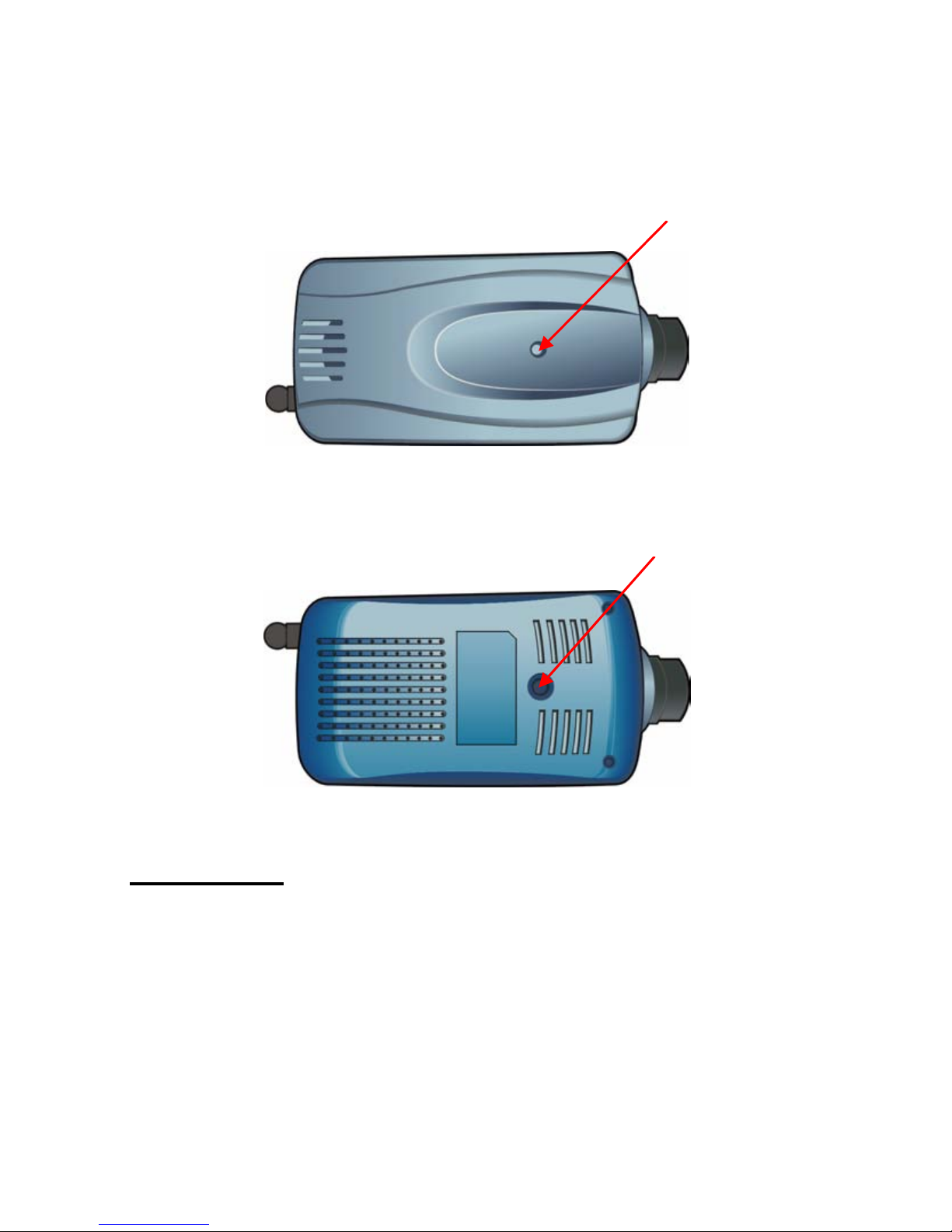
Top/Bottom Panel
Top Panel
Bottom Panel
Screw Hole
Screw Hole
Screw Hole
Located on the top/bottom panel of the camera, the screw hole is
used to connect the camera stand onto the camera by attaching the
screw head on the camera stand into the screw hole of the camera.
14

2
HARDWARE
INSTALLATION
Attaching the Camera to the Stand
The Wireless Internet Camera
comes with a camera stand
(optional) with a swivel ball
screw head that can be attached
to the Wireless Internet
Camera's bottom screw hole.
Attach the camera stand to the
Wireless Internet Camera and
station it for your application.
There are three holes located in
the base of the camera stand
allowing the Wireless Internet
Camera to be mounted on the
ceiling or any wall securely.
15
Connecting the Ethernet cable
Connect an Ethernet cable to
the network cable connector
located on the Wireless Internet
Camera’s rear panel, and then
attach it to the network.
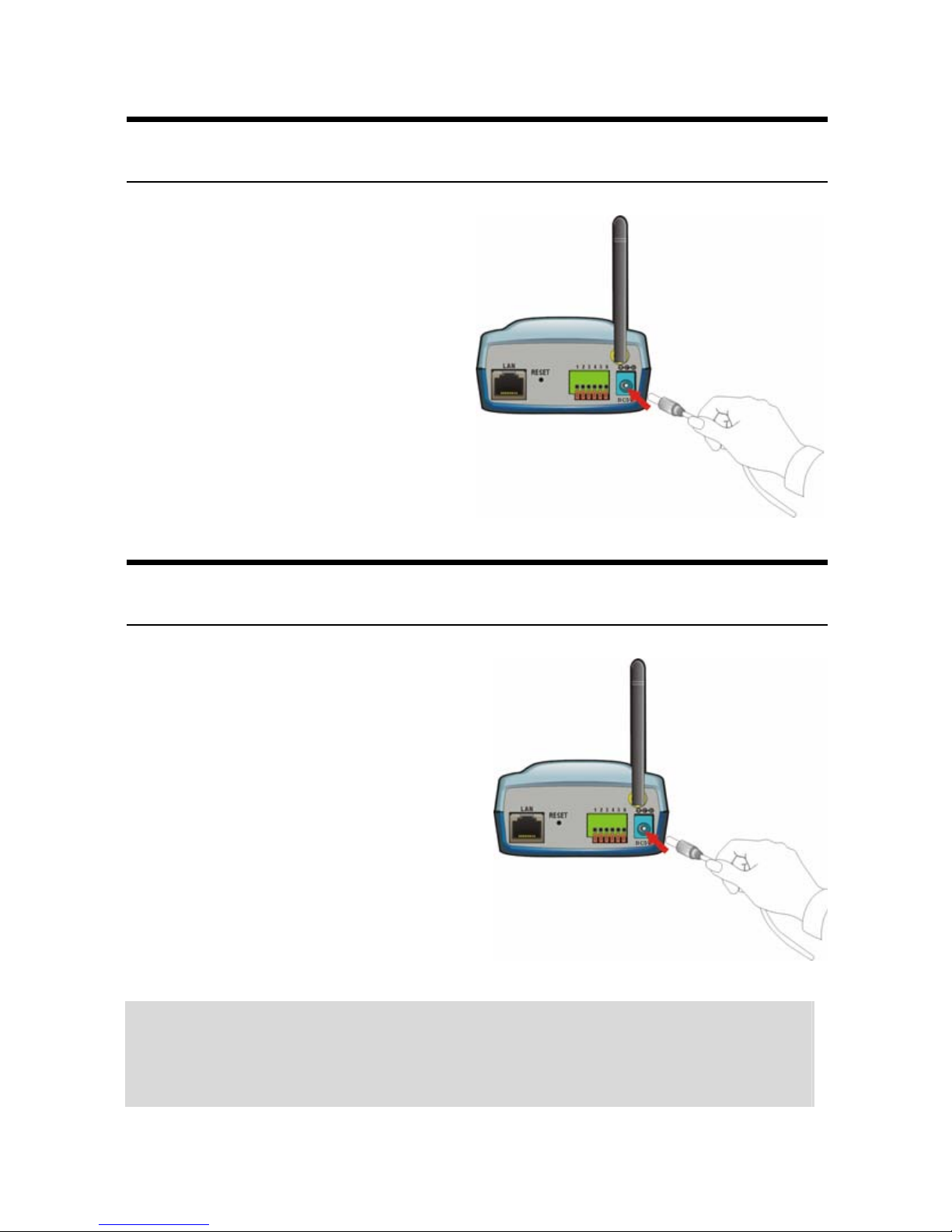
Attaching the Power Supply
Attach the external power
supply to the DC power input
connector located on Wireless
Internet Camera’s rear panel,
and then connect it to your local
power supply.
TIP: You can confirm power source is supplied from the LED
indicators label Power on the Wireless Internet Camera is
illuminated.
16

3
SECURITY
To ensure the highest security and prevent unauthorized usage of
the Wireless Internet Camera the Administrator has the exclusive
privilege to access the System Administration for settings and
control requirements to allow users the level of entry and
authorize the privileges for all users. The Wireless Internet
Camera supports multi-level password protection and access to
the Wireless Internet Camera is strictly restricted to defined the
user who has a “User Name” and “User Password” that is
assigned by the Administrator.
The administrator can release a public user name and password so
when remote users access the Wireless Internet Camera they will
have the right to view the image transmitted by the Wireless
Internet Camera.
NOTE: Since the default settings are Null String, it is highly
recommended to set the "Admin ID" and "Admin Password"
when you are the first time to use the Wireless Internet
Camera. Once the ID and Password are defined, only the
administrator has the access to management the Wireless
Internet Camera. This procedure should be done as soon as
possible since the security features with the Wireless Internet
Camera will not be enabled until the "Admin ID" and "Admin
Password" is defined.
17

4
APPLICATION OF
THE CAMERA
The Wireless Internet Camera can be applied in wide variety of
applications. With the built-in CPU, it can work as a standalone
system that provides a web-based solution transmitting high
quality video images and sounds for monitoring purposes. It can
be managed remotely, accessed and controlled from any PC
desktop over the Intranet or Internet via a web browser. With the
easy installation procedure, real-time live images will be available.
In addition, once the Wireless Internet Camera is installed
coupled with the IPView Pro application, you can further expand
the scope of the Wireless Internet Camera.
The following section will provide the typical applications for the
Wireless Internet Camera along with the IPView Pro application,
and also includes some basic knowledge to assist in the
installation and configuration of the Wireless Internet Camera.
18

Applications
z Monitoring of local and remote places and objects such as
construction sites, hospitals, amusement parks, schools and
day-care centers through the use of a web browser.
z Capture single frame images from the IPView Pro
application.
z Configure the camera to upload image or send-mail
messages with a single frame image.
19
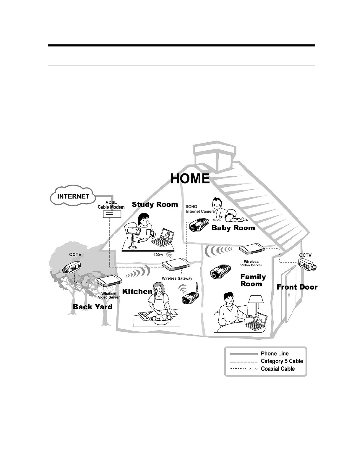
Application Diagrams of the Camera
Home Applications
SOHO
Internet Camera
SOHO Wireless
Internet Camera
20
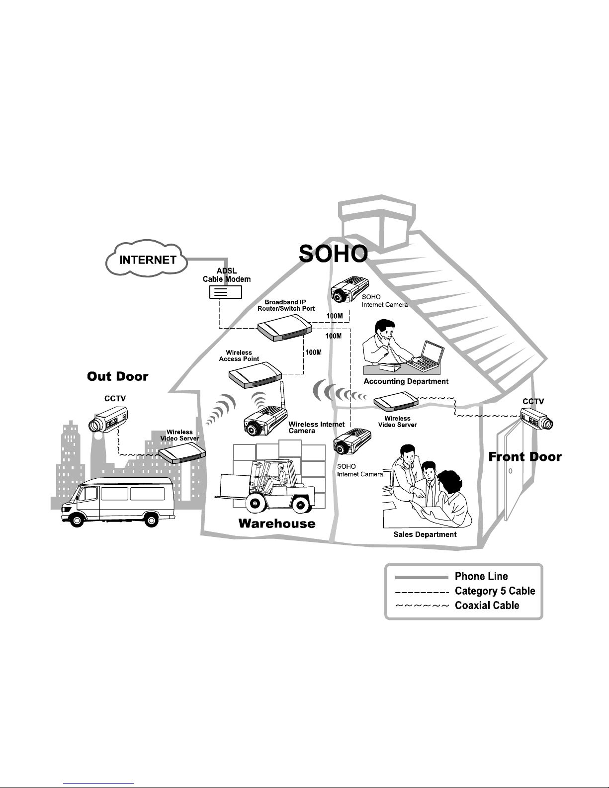
SOHO Applications
SOHO
21

5
USING THE CAMERA
You can access and manage the Wireless Internet Camera through:
1) a web browser, and 2) the enclosed software IPView Pro. This
chapter describes the Web Configuration Utility, and provides the
instructions on using the camera with a web browser.
Web Configuration Utility
The Wireless Internet Camera must be configured through its
built-in Web-based Configuration. (Extensive knowledge of LAN
will be helpful in setting up the Wireless Internet Camera.)
From the web browser, enter the default IP address 192.168.0.30
in the Address bar and then press [Enter] to access the Welcome
screen of the Configuration Utility. The Welcome screen is
shown on the next page.
NOTE: The computer’s IP address must correspond with the
camera’s IP address in the same segment for the two devices
to communicate.
22
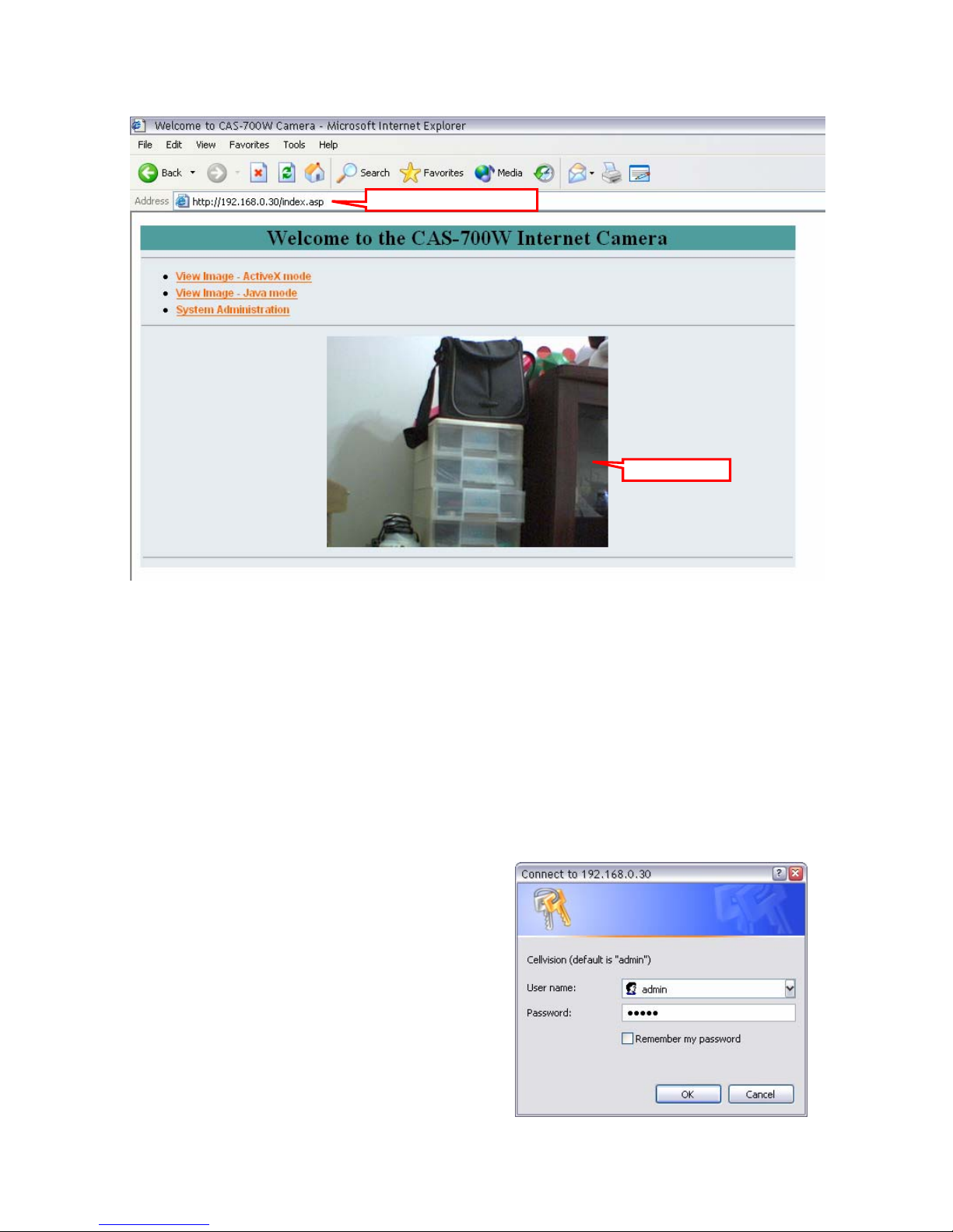
Enter the default IP address
Pre-view area
Welcome Screen of the Configuration Utility
In the Welcome screen, there are three options to choose to set-up
and view your Wireless Internet Camera, including:
z View Video – ActiveX Mode
z View Video – Java Mode
z System Administration
Click System Administration to
prompt a login dialog window,
and type the default username/
password (admin/admin) in the
corresponding boxes. Then, click
OK to enter the Configuration
Utility.
23

System Administration
The Configuration Utility contains ten options in the top menu
bar, including: System, Date/Time, Video/Audio, Network,
Users, Trigger, Upload, Information, Tools, and Home.
TIP: Once you have changed the settings in each option, click
Save to store the settings, or Cancel to abandon, or Refresh to
reload the status. During the configuration, whenever you click
Home in the top menu bar will make you return to the Welcome
window.
System
The System window contains the settings for identifying the
camera, including Camera Name and Location.
Camera Name
This field is used for entering a descriptive name for the device.
Location
This field is used for entering a descriptive name for the location
used by the camera.
24
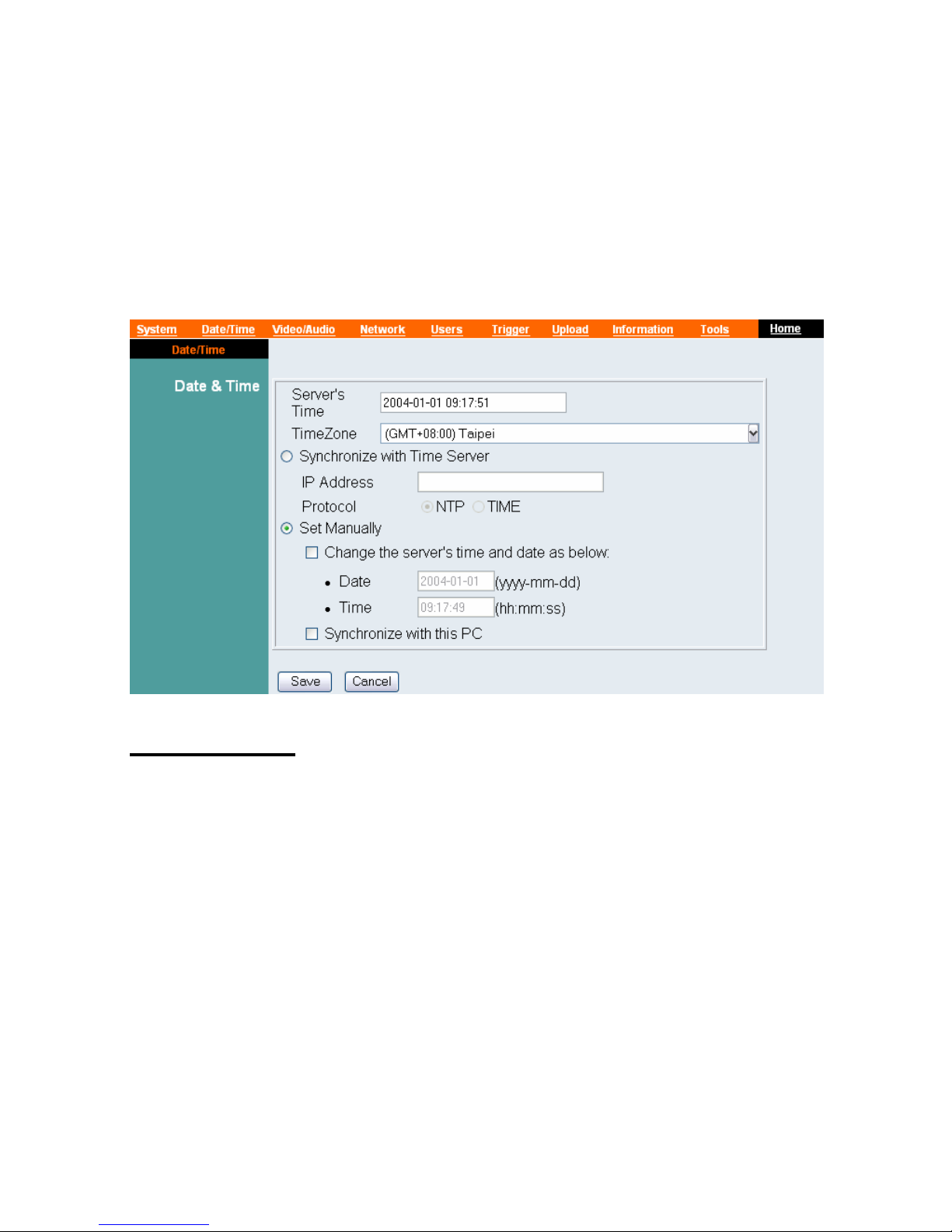
Date/Time
The Date/Time window contains commands to set up the camera's
time and date, providing correct information to the remote users
who might be thousands of miles away from the camera’s
location.
Date & Time
- Server’s Time: Display the current date/time settings of the
camera.
- TimeZone: Select the time zone for the region from the pull-
down menu. (Please refer to the Appendix for the time zone
selection table.)
- Synchronized with Time Server: Select this option and the
time will be based on GMT setting. When selecting the
option, you have to enter the required information in the
following fields:
• IP Address - Enter the IP Address of the Time Server in
this field.
25
• Protocol – Select proper protocol: NTP or TIME.
- Set Manually: This option allows the system administrator to
set date/time manually. Select the Change the server’s time
and date as below item to enter Date and Time in the
respective field manually, or select the Synchronize with this
PC item to set up date/time according to the connected PC’s
configuration.
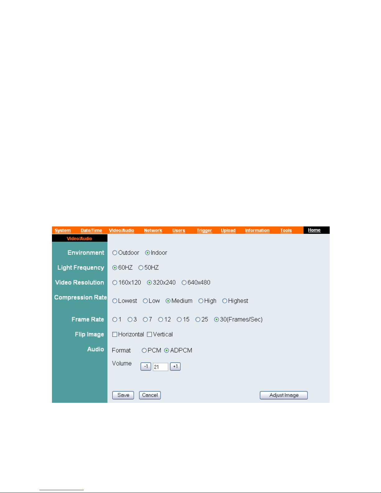
Video/Audio
The Video/Audio window contains commands to control the
image and audio settings of the camera.
26

Environment
Select Outdoor or Indoor according to the installation location
of the camera.
Light Frequency
Select 60HZ or 50HZ.
Video Resolution
Select the desired video resolution from three formats: 160x120,
320x240, and 640x480. The higher setting can obtain better
quality; however, it will use more resource within your network.
Compression Rate
Select the desired compression rate from five levels: Lowest,
Low, Medium, High, and Highest. The higher compression rate
can increase the data transmission over the network; however, it
will provide poorer image quality.
Frame Rate
Select the optimal setting depending on your network status.
Please note that the higher setting can obtain better quality;
however, it will use more resource within your network. The
available settings are 1, 3, 7, 12, 15, 25 and 30.
Flip Image
Select Horizontal to display the image in a horizontal mirror
mode. Select Vertical to display the image in a vertical mirror
mode.
27
Audio
Select the audio format as PCM or ADPCM. Then, you can also
adjust the Volume of the camera.
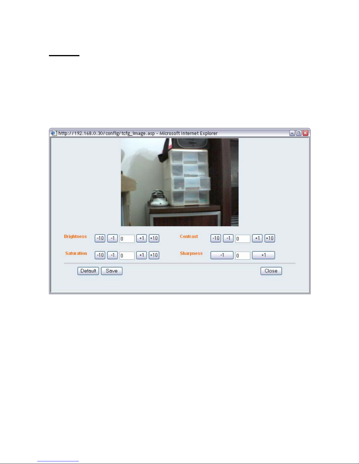
In addition, clicking Adjust Image will bring up the following
window, which allows you to adjust the image settings:
- Brightness: Adjust the brightness level ranging from -64 to
+64.
- Saturation: Adjust the colors level ranging from -64 to +64.
- Contrast: Adjust the contrast level ranging from -64 to +64.
- Sharpness: Adjust the sharpness level ranging from -6 to +6.
28
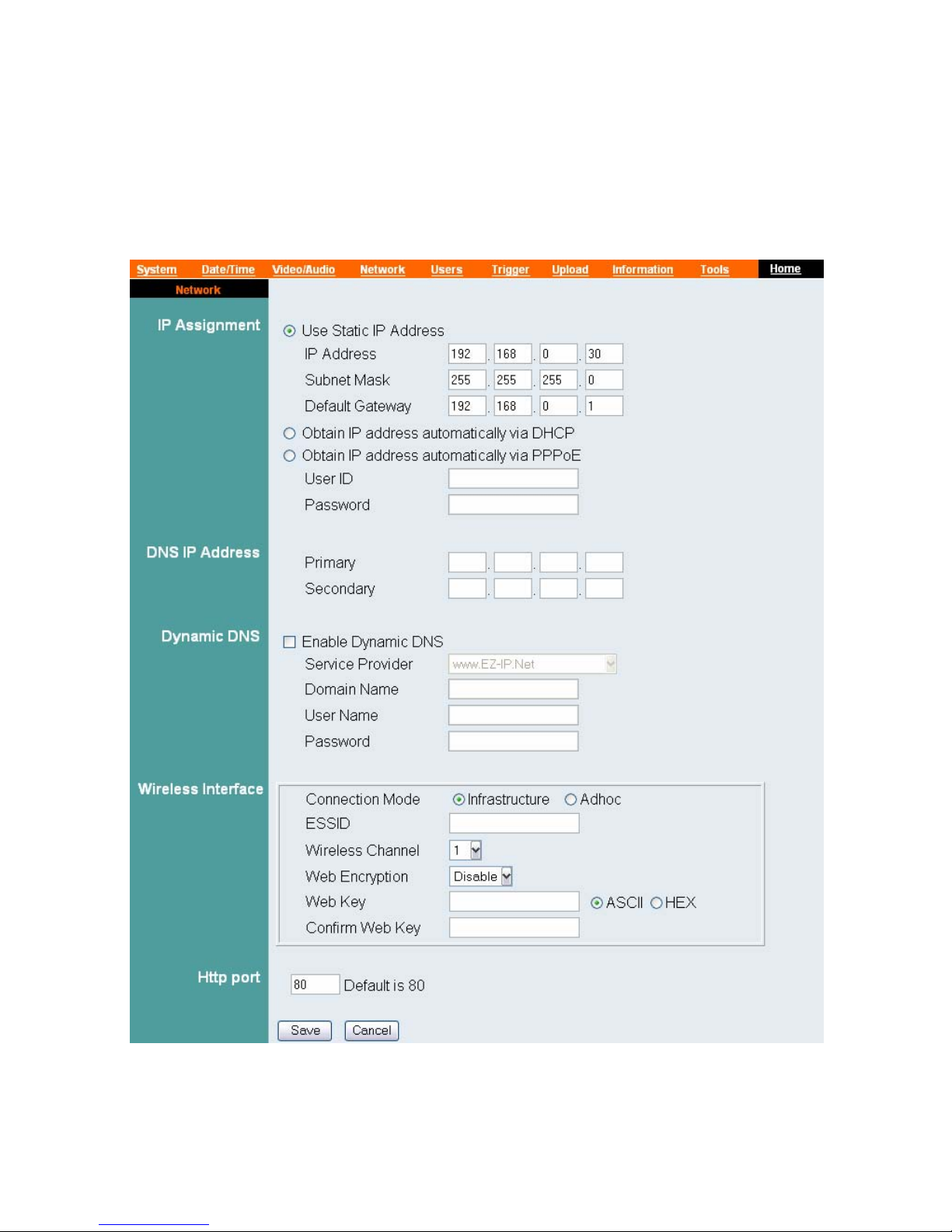
Network
The Network window contains commands that allow you to set
up networking configuration of the camera.
29

IP Assignment
- Use Static IP Address: You can select this option and enter
the IP address directly. The default settings are:
• IP Address – 192.168.0.30
• Subnet Mask – 255.255.255.0
• Default Gateway – 192.168.0.1
- Obtain IP address automatically via DHCP: If your
network uses the DHCP server, select this option. According
to this setting, the camera will be assigned an IP address from
the DHCP server automatically. Every time when the camera
starts up, please make sure that the DHCP server is set to
assign a static IP address to your camera.
- Obtain IP address automatically via PPPoE: If your
application requires a direct connection from an ADSL
modem through the camera’s RJ-45 LAN port, click this
option and enter the User ID and Password into the respective
boxes. (Note: You should have an ISP PPPoE account.) The
camera will get an IP address from the ISP as starting up.
DNS IP Address
DNS (Domain Name System) server is an Internet service that
translates domain names into IP addresses. Enter at least one
DNS IP address.
Dynamic DNS
Check the Enable Dynamic DNS item to enable the Dynamic
DNS function, which allows you to run your domain over a
changing IP address. Select one Dynamic DNS provider from the
pull-down menu, and then enter the required information in the
following fields, including the Domain Name, User Name, and
Password.
30
 Loading...