

Sparc S7-2L Service Manual

SPARC S7-2L Server Service Manual
Part No: E73201-04
March 2017


SPARC S7-2L Server Service Manual
Part No: E73201-04
Copyright © 2016, 2017, Oracle and/or its affiliates. All rights reserved.
This software and related documentation are provided under a license agreement containing restrictions on use and disclosure and are protected by intellectual property laws. Except
as expressly permitted in your license agreement or allowed by law, you may not use, copy, reproduce, translate, broadcast, modify, license, transmit, distribute, exhibit, perform,
publish, or display any part, in any form, or by any means. Reverse engineering, disassembly, or decompilation of this software, unless required by law for interoperability, is
prohibited.
The information contained herein is subject to change without notice and is not warranted to be error-free. If you find any errors, please report them to us in writing.
If this is software or related documentation that is delivered to the U.S. Government or anyone licensing it on behalf of the U.S. Government, then the following notice is applicable:
U.S. GOVERNMENT END USERS: Oracle programs, including any operating system, integrated software, any programs installed on the hardware, and/or documentation,
delivered to U.S. Government end users are "commercial computer software" pursuant to the applicable Federal Acquisition Regulation and agency-specific supplemental
regulations. As such, use, duplication, disclosure, modification, and adaptation of the programs, including any operating system, integrated software, any programs installed on the
hardware, and/or documentation, shall be subject to license terms and license restrictions applicable to the programs. No other rights are granted to the U.S. Government.
This software or hardware is developed for general use in a variety of information management applications. It is not developed or intended for use in any inherently dangerous
applications, including applications that may create a risk of personal injury. If you use this software or hardware in dangerous applications, then you shall be responsible to take all
appropriate fail-safe, backup, redundancy, and other measures to ensure its safe use. Oracle Corporation and its affiliates disclaim any liability for any damages caused by use of this
software or hardware in dangerous applications.
Oracle and Java are registered trademarks of Oracle and/or its affiliates. Other names may be trademarks of their respective owners.
Intel and Intel Xeon are trademarks or registered trademarks of Intel Corporation. All SPARC trademarks are used under license and are trademarks or registered trademarks of
SPARC International, Inc. AMD, Opteron, the AMD logo, and the AMD Opteron logo are trademarks or registered trademarks of Advanced Micro Devices. UNIX is a registered
trademark of The Open Group.
This software or hardware and documentation may provide access to or information about content, products, and services from third parties. Oracle Corporation and its affiliates are
not responsible for and expressly disclaim all warranties of any kind with respect to third-party content, products, and services unless otherwise set forth in an applicable agreement
between you and Oracle. Oracle Corporation and its affiliates will not be responsible for any loss, costs, or damages incurred due to your access to or use of third-party content,
products, or services, except as set forth in an applicable agreement between you and Oracle.
Access to Oracle Support
Oracle customers that have purchased support have access to electronic support through My Oracle Support. For information, visit http://www.oracle.com/pls/topic/lookup?
ctx=acc&id=info or visit http://www.oracle.com/pls/topic/lookup?ctx=acc&id=trs if you are hearing impaired.

Référence: E73201-04
Copyright © 2016, 2017, Oracle et/ou ses affiliés. Tous droits réservés.
Ce logiciel et la documentation qui l'accompagne sont protégés par les lois sur la propriété intellectuelle. Ils sont concédés sous licence et soumis à des restrictions d'utilisation et
de divulgation. Sauf stipulation expresse de votre contrat de licence ou de la loi, vous ne pouvez pas copier, reproduire, traduire, diffuser, modifier, accorder de licence, transmettre,
distribuer, exposer, exécuter, publier ou afficher le logiciel, même partiellement, sous quelque forme et par quelque procédé que ce soit. Par ailleurs, il est interdit de procéder à toute
ingénierie inverse du logiciel, de le désassembler ou de le décompiler, excepté à des fins d'interopérabilité avec des logiciels tiers ou tel que prescrit par la loi.
Les informations fournies dans ce document sont susceptibles de modification sans préavis. Par ailleurs, Oracle Corporation ne garantit pas qu'elles soient exemptes d'erreurs et vous
invite, le cas échéant, à lui en faire part par écrit.
Si ce logiciel, ou la documentation qui l'accompagne, est livré sous licence au Gouvernement des Etats-Unis, ou à quiconque qui aurait souscrit la licence de ce logiciel pour le
compte du Gouvernement des Etats-Unis, la notice suivante s'applique :
U.S. GOVERNMENT END USERS: Oracle programs, including any operating system, integrated software, any programs installed on the hardware, and/or documentation,
delivered to U.S. Government end users are "commercial computer software" pursuant to the applicable Federal Acquisition Regulation and agency-specific supplemental
regulations. As such, use, duplication, disclosure, modification, and adaptation of the programs, including any operating system, integrated software, any programs installed on the
hardware, and/or documentation, shall be subject to license terms and license restrictions applicable to the programs. No other rights are granted to the U.S. Government.
Ce logiciel ou matériel a été développé pour un usage général dans le cadre d'applications de gestion des informations. Ce logiciel ou matériel n'est pas conçu ni n'est destiné à être
utilisé dans des applications à risque, notamment dans des applications pouvant causer un risque de dommages corporels. Si vous utilisez ce logiciel ou ce matériel dans le cadre
d'applications dangereuses, il est de votre responsabilité de prendre toutes les mesures de secours, de sauvegarde, de redondance et autres mesures nécessaires à son utilisation dans
des conditions optimales de sécurité. Oracle Corporation et ses affiliés déclinent toute responsabilité quant aux dommages causés par l'utilisation de ce logiciel ou matériel pour des
applications dangereuses.
Oracle et Java sont des marques déposées d'Oracle Corporation et/ou de ses affiliés. Tout autre nom mentionné peut correspondre à des marques appartenant à d'autres propriétaires
qu'Oracle.
Intel et Intel Xeon sont des marques ou des marques déposées d'Intel Corporation. Toutes les marques SPARC sont utilisées sous licence et sont des marques ou des marques
déposées de SPARC International, Inc. AMD, Opteron, le logo AMD et le logo AMD Opteron sont des marques ou des marques déposées d'Advanced Micro Devices. UNIX est une
marque déposée de The Open Group.
Ce logiciel ou matériel et la documentation qui l'accompagne peuvent fournir des informations ou des liens donnant accès à des contenus, des produits et des services émanant de
tiers. Oracle Corporation et ses affiliés déclinent toute responsabilité ou garantie expresse quant aux contenus, produits ou services émanant de tiers, sauf mention contraire stipulée
dans un contrat entre vous et Oracle. En aucun cas, Oracle Corporation et ses affiliés ne sauraient être tenus pour responsables des pertes subies, des coûts occasionnés ou des
dommages causés par l'accès à des contenus, produits ou services tiers, ou à leur utilisation, sauf mention contraire stipulée dans un contrat entre vous et Oracle.
Accès aux services de support Oracle
Les clients Oracle qui ont souscrit un contrat de support ont accès au support électronique via My Oracle Support. Pour plus d'informations, visitez le site http://www.oracle.com/
pls/topic/lookup?ctx=acc&id=info ou le site http://www.oracle.com/pls/topic/lookup?ctx=acc&id=trs si vous êtes malentendant.

Contents
Using This Documentation ................................... .............................................. 9
Product Documentation Library . ..................................................................... ... 9
Feedback ................................... .................................................................... 9
Identifying Components ................................................................ .................... 11
Front Panel Components with Eight Drives .................... .................... ................ 11
Front Panel Components with Twelve-3.5-Inch-Drive Backplane ............................ 13
Front Panel Components with Twenty-Four-Drive Backplane ................................ 15
Front Panel Components with Twelve NVMe Drive Backplane .............................. 18
Rear Panel Components .............................................. .................................... 19
Internal Component Locations .................................................. .................... ... 20
Device Paths ...................... ..................................................................... ...... 23
Detecting and Managing Faults ............ .................... ........................................ 27
Checking for Faults ..................................................... .................................. 27
▼ Log In to Oracle ILOM (Service) ..................................... ................... 28
▼ Identify Faulted Components ............. ................................................. 28
▼ Identify Disabled Components ............................................................ 30
Component Names Displayed by Diagnostic Software ............... .................. 31
Interpreting LEDs .... ..................................................................... ................. 33
Front Panel Controls and LEDs ........... .................................................... 34
Rear Panel Controls and LEDs .................... ............................................ 35
Performing Advanced Troubleshooting .... .................... ...................................... 36
▼ Check the Message Buffer .............................................. ................... 37
▼ View Log Files (Oracle Solaris) ..................... ..................................... 37
▼ View Log Files (Oracle ILOM) .......... ................................................ 38
POST Overview .... ..................................................................... ........... 39
▼ Configure POST ............... ............................................................... 39
5

Contents
Oracle ILOM Properties That Affect POST Behavior ......... .......................... 41
▼ Clear a Fault Manually ....................... ...................................................... 42
Preparing for Service .. ..................................................................... ................. 45
Safety Information ........................ ................................................................. 45
Safety Symbols ................................. .................... ................................ 46
ESD Measures ............. .................... ..................................................... 46
Antistatic Wrist Strap Use .................... ................................................... 46
Antistatic Mat ............. ..................................................................... ..... 47
Tools Needed For Service ............. .................................................................. 47
Fillers ................................... ..................................................................... .. 47
▼ Find the Server Serial Number .......... ......................................................... 48
▼ Locate the Server ........................ ............................................................. 49
Component Service Categories . .................... ................................................... 49
Removing Power From the Server ............................... .................... ................. 50
▼ Prepare to Power Off the Server ........ .................... ............................. 51
▼ Power Off the Server (Oracle ILOM) ................................................... 52
▼ Power Off the Server (Server Power Button - Graceful) ........................... 52
▼ Power Off the Server (Emergency Shutdown) ................................... ..... 53
▼ Disconnect Power Cords ........................................................ ........... 53
Accessing Server Components . ..................................................................... ... 54
▼ Prevent ESD Damage ................................ .................... ................... 54
▼ Extend the Server to the Service Position ......................... .................... 55
▼ Release the CMA .............................................. .................... ........... 56
▼ Remove the Server From the Rack .............................. .................... .... 58
▼ Remove the Top Cover ............ ......................................................... 59
▼ Remove the Air Baffle .................... .................................................. 60
▼ Remove the Fan Cover ........................................................ .............. 60
Attachment of Devices During Service ..................................... ......................... 62
Servicing Drives ................................................... ............................................. 65
Drive LEDs .. ..................................................................... ........................... 66
▼ Determine Which Drive Is Faulty ............................................. .................. 67
▼ Remove a Drive or Drive Filler ................ .................... .............................. 68
▼ Install a Drive or Drive Filler ......................................... ............................ 72
▼ Verify a Drive .............................................................. .................... ....... 73
6 SPARC S7-2L Server Service Manual • March 2017

Contents
Servicing Fan Modules ............. .................... .................................................... 77
Fan Module LEDs .............................................................. .................... ....... 78
▼ Determine Which Fan Module Is Faulty ....................................................... 79
▼ Remove a Fan Module ... ................................................. .................... ...... 79
▼ Install a Fan Module ....................................... .......................................... 82
▼ Verify a Fan Module ................................ ................................................. 85
Servicing Power Supplies ................................... .................... .......................... 87
▼ Locate a Faulty Power Supply ................... ................................................. 87
▼ Remove a Power Supply ................ ................................................. .......... 88
▼ Install a Power Supply .................................................... .......................... 89
▼ Verify a Power Supply ............................................. .................... ............. 91
Servicing DIMMs .. ..................................................................... ........................ 93
DIMM Configuration ............... ..................................................................... . 93
DIMM FRU Names .... ..................................................................... .............. 94
▼ Locate a Failed DIMM (LEDs) . .................... .............................................. 95
▼ Locate a Failed DIMM (Oracle ILOM) ........................................... ............. 96
▼ Remove a DIMM ........................ .................... ......................................... 97
▼ Install a DIMM ................................................... ..................................... 98
▼ Enable and Verify a DIMM ................... ................................................... 100
Servicing PCIe Cards .............................................................. ........................ 103
PCIe Card Configuration ........ ..................................................................... .. 103
▼ Remove a PCIe Card or Filler ............................................. ..................... 104
▼ Install a PCIe Card or Filler . .................................................................... 106
Servicing the eUSB Drive .............................................. .................................. 109
▼ Remove the eUSB Drive .................. ....................................................... 109
▼ Install the eUSB Drive ..... ................................................. .................... .. 111
Servicing the Battery .......................................... .................... ......................... 113
▼ Replace the Battery ................................................ ................................. 113
Servicing the Motherboard ................. ............................................................. 117
7

Contents
▼ Remove the Motherboard .................................... ..................................... 117
▼ Install the Motherboard ........................................... .................... ............ 123
▼ Verify the Motherboard ........................................................ ................... 130
Servicing the Drive Backplane ................................ ........................................ 131
▼ Remove the Eight-Drive Backplane ........................................................... 131
▼ Install the Eight-Drive Backplane ................................ .................... .......... 134
▼ Remove the Twelve-Drive Backplane .............. .................... ....................... 135
▼ Install the Twelve-Drive Backplane ........................................................... 138
▼ Remove the Twelve-Drive NVMe Backplane ................ ............................... 139
▼ Install the Twelve-Drive NVMe Backplane ............ ..................................... 141
▼ Remove the Twenty Four-Drive Backplane ............ ..................................... 142
▼ Install the Twenty Four-Drive Backplane ........ ............................................ 144
▼ Remove the Rear Drive Backplane ........................................ .................... 145
▼ Install the Rear Drive Backplane .................................... .................... ....... 147
Returning the Server to Operation ........... ....................................................... 149
▼ Replace the Fan Cover ..... ................................................. .................... .. 149
▼ Install the Air Baffle ......................... ...................................................... 151
▼ Replace the Top Cover .......... .................... .............................................. 152
▼ Return the Server to the Normal Operating Position ........ .................... .......... 153
▼ Attach Power Cords ................... .................... ......................................... 154
▼ Power On the Server (Oracle ILOM) ......................................... ................ 154
▼ Power On the Server (System Power Button) ............................. .................. 155
Index ................................... ..................................................................... ........ 157
8 SPARC S7-2L Server Service Manual • March 2017

Using This Documentation
■
Overview – Describes how to troubleshoot and maintain the server
■
Audience – This guide is intended for trained technicians an authorized service personnel
who have been instructed on the hazards within the equipment and qualified to remove and
replace hardware
■
Required knowledge – Advanced experience troubleshooting and replacing hardware
Product Documentation Library
Documentation and resources for this product and related products are available at http://www.
oracle.com/goto/s7-2l/docs.
Feedback
Provide feedback about this documentation at http://www.oracle.com/goto/docfeedback.
Using This Documentation 9

10 SPARC S7-2L Server Service Manual • March 2017

Identifying Components
These topics identify key components of the server, including major boards and internal system
cables, as well as front and rear panel features.
■
“Front Panel Components with Eight Drives” on page 11
■
“Front Panel Components with Twelve-3.5-Inch-Drive Backplane” on page 13
■
“Front Panel Components with Twenty-Four-Drive Backplane” on page 15
■
“Front Panel Components with Twelve NVMe Drive Backplane” on page 18
■
“Internal Component Locations” on page 20
■
“Device Paths” on page 23
Related Information
■
“Detecting and Managing Faults” on page 27
■
“Preparing for Service” on page 45
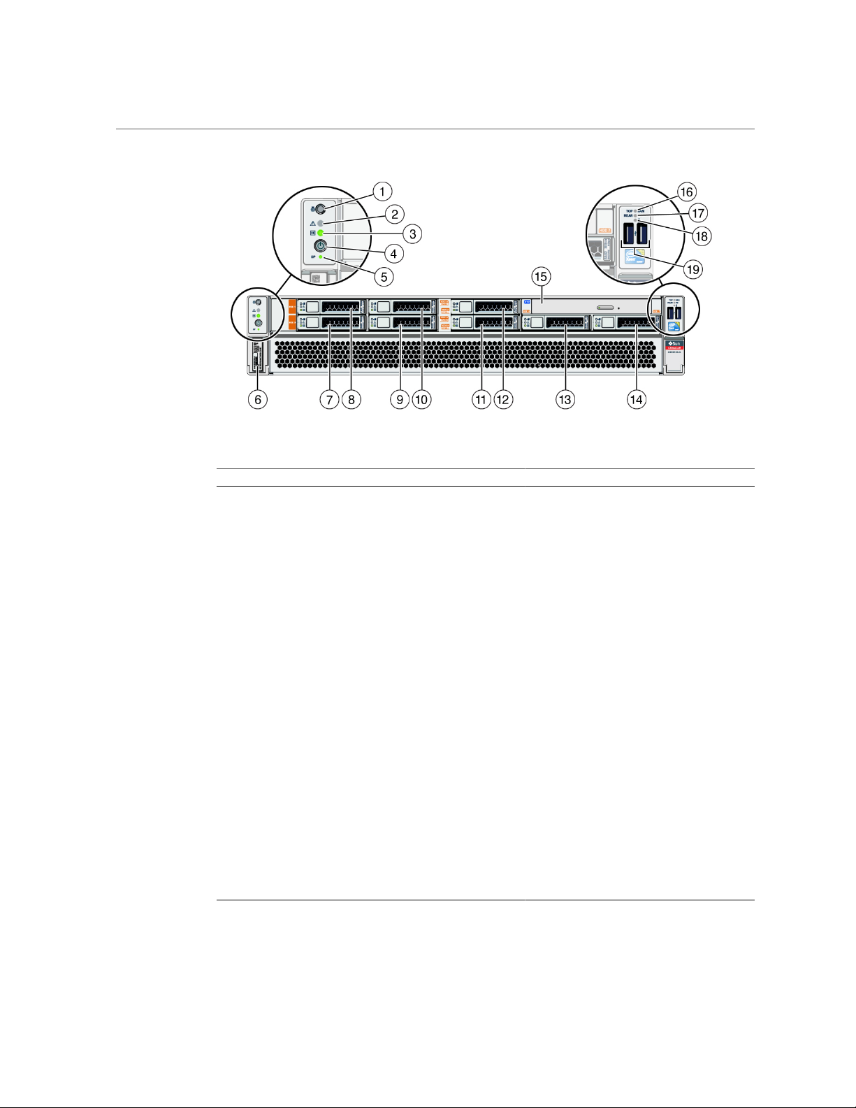
Front Panel Components with Eight Drives
The following figure shows the layout of the server front panel, including the power and server
locator buttons and the various status and fault LEDs.
Note - The front panel also provides access to internal drives, the removable media drive (if
equipped), and the two front USB ports.
Identifying Components 11
Front Panel Components with Eight Drives
No. Description Links
1 Server Locator LED/Locator button (white) “Front Panel Controls and
2 Service Required LED (amber) “Front Panel Controls and
3 Power LED (green) “Front Panel Controls and
4 Server Power button “Front Panel Controls and
5 SP Fault LED (green or amber) “Front Panel Controls and
6 Serial number “Find the Server Serial Number” on page 48
7 HDD 0 “Servicing Drives” on page 65
8 HDD 1 “Servicing Drives” on page 65
9 HDD 2 or NVMe 0 “Servicing Drives” on page 65
LEDs” on page 34
LEDs” on page 34
LEDs” on page 34
LEDs” on page 34
LEDs” on page 34
10 HDD 3 or NVMe 1 “Servicing Drives” on page 65
11 HDD 4 or NVMe 2 “Servicing Drives” on page 65
12 HDD 5 or NVMe 3 “Servicing Drives” on page 65
13 HDD 6 “Servicing Drives” on page 65
14 HDD 7 “Servicing Drives” on page 65
15 DVD drive (not available on this server)
16 Fan Service LEDs (amber) “Servicing Fan Modules” on page 77
17 Power Supply (PS) Service LED (amber) “Servicing Power Supplies” on page 87
12 SPARC S7-2L Server Service Manual • March 2017
Front Panel Components with Twelve-3.5-Inch-Drive Backplane
No. Description Links
18 Server Overtemp LED (amber) “Front Panel Controls and
19 USB 2.0 connectors (2) “USB Ports” in SPARC S7-2L Server
LEDs” on page 34
Installation Guide
Related Information
■
“Rear Panel Components” on page 19
■
“Internal Component Locations” on page 20
■
“Device Paths” on page 23
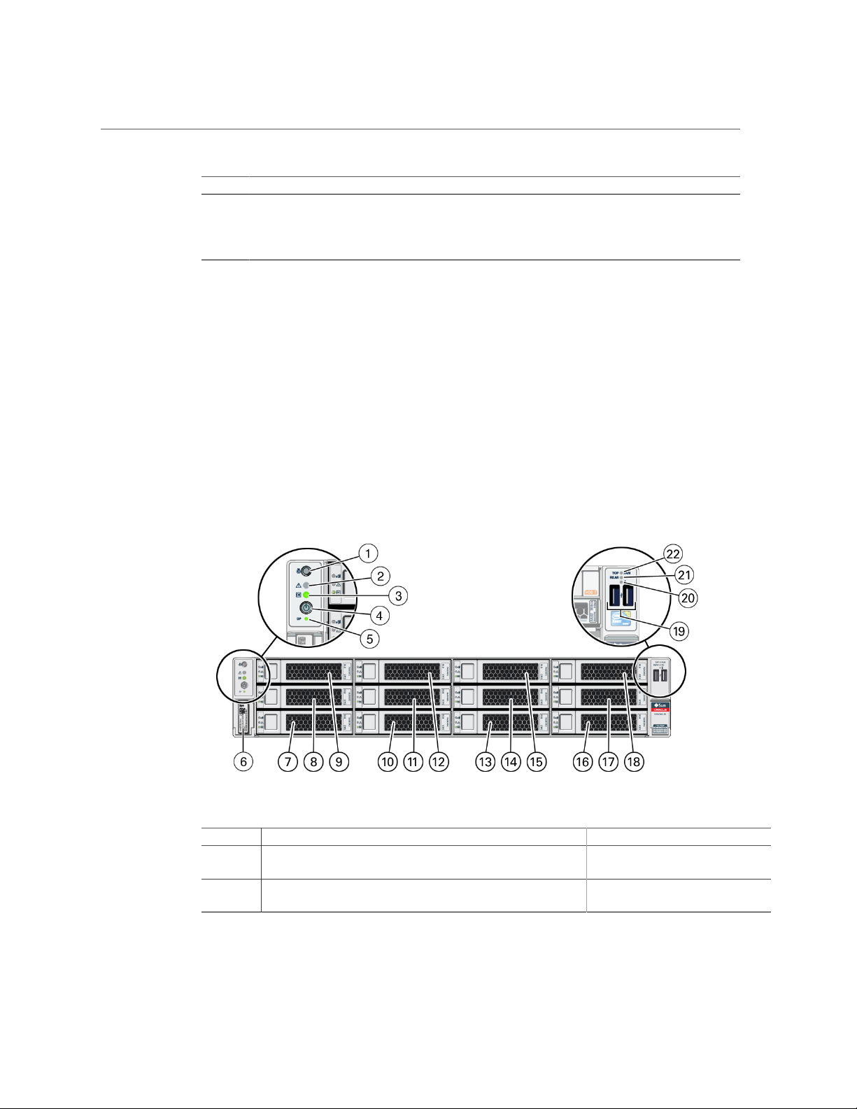
Front Panel Components with Twelve-3.5-Inch-Drive
Backplane
No. Description Links
1 Locator button / Locator LED (white) “Front Panel Controls and
2 Service Required LED (amber) “Front Panel Controls and
LEDs” on page 34
LEDs” on page 34
Identifying Components 13

Front Panel Components with Twelve-3.5-Inch-Drive Backplane
No. Description Links
3 Power LED (green) “Front Panel Controls and
4 Power button “Front Panel Controls and
5 SP Power OK button (green) “Front Panel Controls and
6 Server serial number “Find the Server Serial
7 Drive 0 “Servicing Drives” on page 65
8 Drive 4 “Servicing Drives” on page 65
9 Drive 8 “Servicing Drives” on page 65
10 Drive 1 “Servicing Drives” on page 65
11 Drive 5 “Servicing Drives” on page 65
12 Drive 9 “Servicing Drives” on page 65
13 Drive 2 “Servicing Drives” on page 65
14 Drive 6 “Servicing Drives” on page 65
15 Drive 10 “Servicing Drives” on page 65
16 Drive 3 “Servicing Drives” on page 65
17 Drive 7 “Servicing Drives” on page 65
18 Drive 11 “Servicing Drives” on page 65
19 USB 2.0 connectors (2) “USB Ports” in SPARC S7-2L Server
20 Overtemperature LED (amber) “Front Panel Controls and
21 PS fault LED “Servicing Power
22 Fan fault LED (amber) “Servicing Fan
LEDs” on page 34
LEDs” on page 34
LEDs” on page 34
Number” on page 48
Installation Guide
LEDs” on page 34
Supplies” on page 87
Modules” on page 77
Related Information
■
“Rear Panel Components” on page 19
■
“Internal Component Locations” on page 20
■
“Device Paths” on page 23
14 SPARC S7-2L Server Service Manual • March 2017
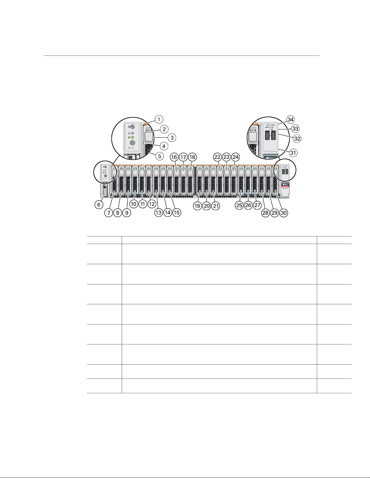
Front Panel Components with Twenty-Four-Drive Backplane
Front Panel Components with Twenty-Four-Drive Backplane
No. Description Links
1 Locator button / Locator LED (white) “Front Panel
2 Service Required LED (amber) “Front Panel
3 Power LED (green) “Front Panel
4 Power button “Front Panel
5 SP Power OK button (green) “Front Panel
6 Server serial number “Find the
7 Drive 0 “Servicing
8 Drive 1 “Servicing
Controls and
LEDs” on page 34
Controls and
LEDs” on page 34
Controls and
LEDs” on page 34
Controls and
LEDs” on page 34
Controls and
LEDs” on page 34
Server Serial
Number” on page 48
Drives” on page 65
Drives” on page 65
Identifying Components 15

Front Panel Components with Twenty-Four-Drive Backplane
No. Description Links
9 Drive 2 “Servicing
10 Drive 3 (or NVMe drive 0) “Servicing
11 Drive 4 (or NVMe drive 1) “Servicing
12 Drive 5 “Servicing
13 Drive 6 “Servicing
14 Drive 7 “Servicing
15 Drive 8 “Servicing
16 Drive 9 “Servicing
17 Drive 10 “Servicing
18 Drive 11 “Servicing
19 Drive 12 “Servicing
20 Drive 13 “Servicing
21 Drive 14 “Servicing
22 Drive 15 “Servicing
23 Drive 16 “Servicing
24 Drive 17 “Servicing
25 Drive 18 “Servicing
26 Drive 19 (or NVMe drive 2) “Servicing
27 Drive 20 (or NVMe drive 3) “Servicing
28 Drive 21 “Servicing
29 Drive 22 “Servicing
Drives” on page 65
Drives” on page 65
Drives” on page 65
Drives” on page 65
Drives” on page 65
Drives” on page 65
Drives” on page 65
Drives” on page 65
Drives” on page 65
Drives” on page 65
Drives” on page 65
Drives” on page 65
Drives” on page 65
Drives” on page 65
Drives” on page 65
Drives” on page 65
Drives” on page 65
Drives” on page 65
Drives” on page 65
Drives” on page 65
Drives” on page 65
16 SPARC S7-2L Server Service Manual • March 2017

Front Panel Components with Twenty-Four-Drive Backplane
No. Description Links
30 Drive 23 “Servicing
31 USB 2.0 connectors (2) “USB Ports”
32 Overtemperature LED (amber) “Front Panel
33 PS fault LED (amber) “Servicing
34 Fan Fault LED (amber) “Servicing Fan
Drives” on page 65
in SPARC S7-
2L Server
Installation
Guide
Controls and
LEDs” on page 34
Power
Supplies” on page 87
Modules” on page 77
Related Information
■
“Rear Panel Components” on page 19
■
“Internal Component Locations” on page 20
■
“Device Paths” on page 23
Identifying Components 17
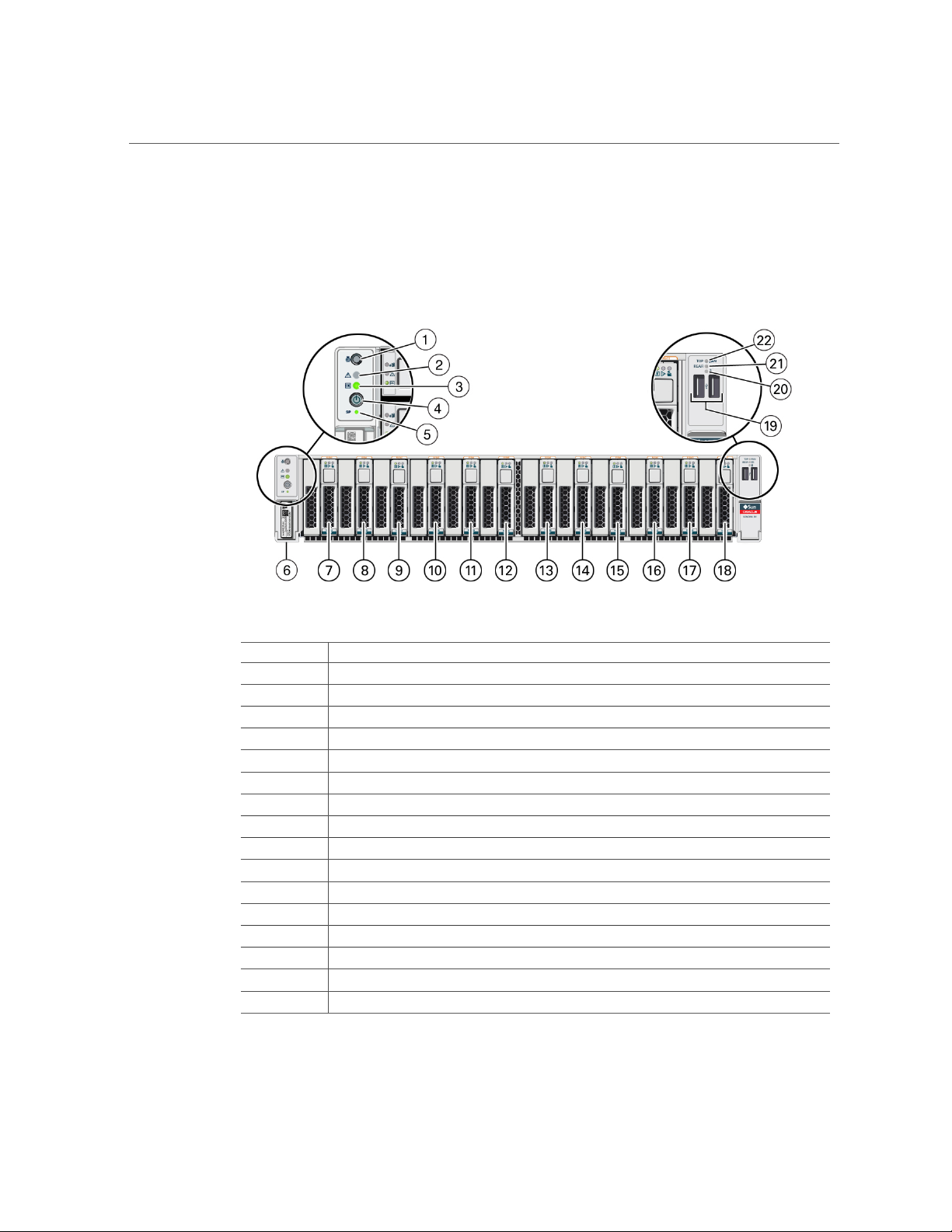
Front Panel Components with Twelve NVMe Drive Backplane
Front Panel Components with Twelve NVMe Drive
Backplane
No. Description
1 Locator button / Locator LED (white)
2 Service Required LED (amber)
3 Power LED (green)
4 Power button
5 SP Power OK button (green)
6 Server serial number
7 NVMe drive 0
8 NVMe drive 1
9 NVMe drive 2
10 NVMe drive 3
11 NVMe drive 4
12 NVMe drive 5
13 NVMe drive 6
14 NVMe drive 7
15 NVMe drive 8
16 NVMe drive 9
18 SPARC S7-2L Server Service Manual • March 2017
No. Description
17 NVMe drive 10
18 NVMe drive 11
19 USB 2.0 connectors (2)
20 Overtemperature LED (amber)
21 PS fault LED (amber)
22 Fan fault LED (amber)
Related Information
■
“Rear Panel Components” on page 19
■
“Internal Component Locations” on page 20
■
“Device Paths” on page 23
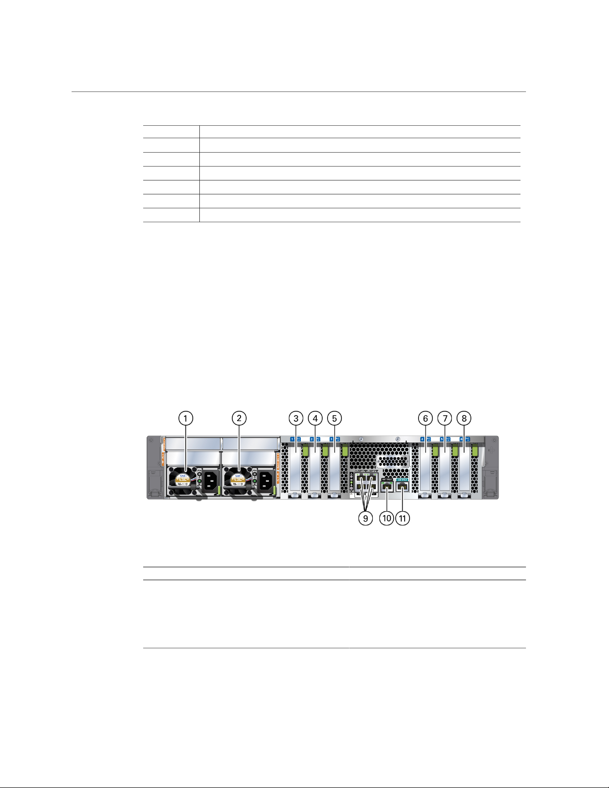
Rear Panel Components
Rear Panel Components
No. Description Links
1 Power supply 0 “Servicing Power Supplies” on page 87
2 Power supply 1 “Servicing Power Supplies” on page 87
3 PCIe card slot 1 “Servicing PCIe Cards” on page 103
4 PCIe card slot 2 “Servicing PCIe Cards” on page 103
5 PCIe card slot 3 “Servicing PCIe Cards” on page 103
Identifying Components 19

Internal Component Locations
No. Description Links
6 PCIe card slot 4 “Servicing PCIe Cards” on page 103
7 PCIe card slot 5 “Servicing PCIe Cards” on page 103
8 PCIe card slot 6 “Servicing PCIe Cards” on page 103
9 10GbE ports (4), NET 0 to NET 3
10 Network management (NET MGT) port
11 Serial management (SER MGT) RJ-45 serial port
Related Information
■
“Front Panel Components with Eight Drives” on page 11
■
“Internal Component Locations” on page 20
■
“Device Paths” on page 23
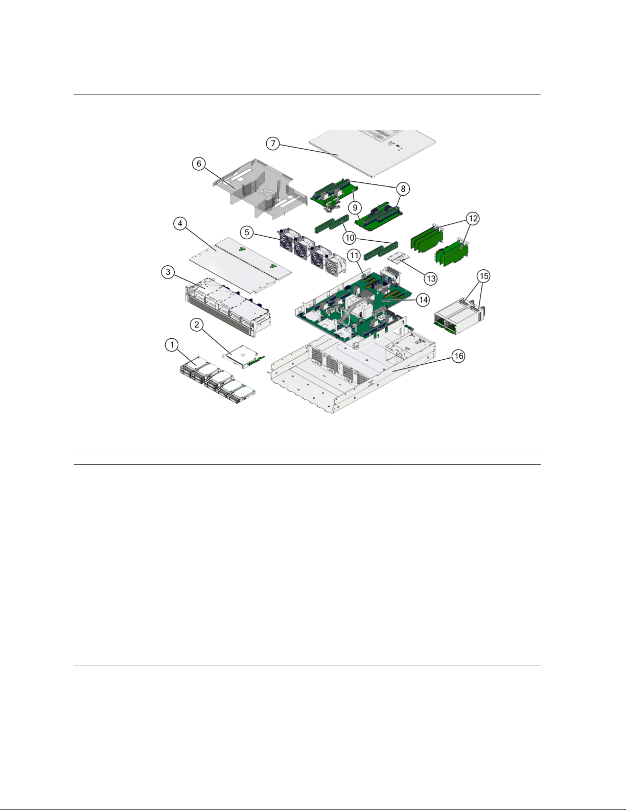
Internal Component Locations
The following figure identifies the replaceable component locations.
20 SPARC S7-2L Server Service Manual • March 2017
Internal Component Locations
No. Component Oracle ILOM Target Links
1 Drives (eight drive configuration in this
/SYS/DBP/HDD0 (lower left)
“Servicing Drives” on page 65
example)
/SYS/DBP/HDD1
/SYS/DBP/HDD2 or /SYS/DBP/NVME0
/SYS/DBP/HDD3 or /SYS/DBP/NVME1
/SYS/DBP/HDD4 or /SYS/DBP/NVME2
/SYS/DBP/HDD5 or /SYS/DBP/NVME3
/SYS/DBP/HDD6
/SYS/DBP/HDD7 (right)
3 Drive backplane (on drive cage)
/SYS/DBP
“Servicing the Drive
Backplane” on page 131
4 Fan module cover “Remove the Fan Cover” on page 60
“Replace the Fan Cover” on page 149
Identifying Components 21

Internal Component Locations
No. Component Oracle ILOM Target Links
5 Fan modules As viewed from front of server:
/SYS/MB/FM0 (left)
/SYS/MB/FM1 (left center)
/SYS/MB/FM2 (right center)
/SYS/MB/FM3 (right)
6 Air baffle “Remove the Air Baffle” on page 60
7 Top cover “Remove the Top Cover” on page 59
8 DIMMs
11 Battery
12 PCIe cards
/SYS/MB/CMP[0-1]/MCU[0-1]/CH[0-1]/
D[0-1]
/SYS/MB/BAT
/SYS/MB/PCIE1
/SYS/MB/PCIE2
/SYS/MB/PCIE3
“Servicing Fan Modules” on page 77
“Install the Air Baffle” on page 151
“Replace the Top Cover” on page 152
“Servicing DIMMs” on page 93
“Servicing the Battery” on page 113
“Servicing PCIe Cards” on page 103
/SYS/MB/PCIE4
/SYS/MB/PCIE5
/SYS/MB/PCIE6
/SYS/MB/PCIE7 (internal PCIe card)
14 Motherboard
14 Processor chip (replaceable only by
replacing the motherboard)
15 Power supplies
16 Chassis
eUSB drive
/SYS/MB
/SYS/MB/CMP[0-1]
/SYS/PS0 (outer)
/SYS/PS1 (inner)
/SYS/MB/EUSB_DISK
Related Information
■
“Component Names Displayed by Diagnostic Software” on page 31
■
“Front Panel Components with Eight Drives” on page 11
■
“Rear Panel Components” on page 19
■
“Internal Component Locations” on page 20
“Servicing the
Motherboard” on page 117
“Servicing the
Motherboard” on page 117
“Servicing Power
Supplies” on page 87
22 SPARC S7-2L Server Service Manual • March 2017

■
“Device Paths” on page 23
Device Paths
These tables include paths that identify components on the server. The device paths can help
you determine the optimum locations for optional cards or other peripherals, based on your
server's configuration and intended use.
This table identifies some key path names in this server.
Device Paths
Device NAC Name Description Device Path PCIe
/SYS/MB/PCIE1
/SYS/MB/PCIE2
/SYS/MB/PCIE3
/SYS/MB/PCIE4
/SYS/MB/PCIE5
/SYS/MB/PCIE6
/SYS/MB/PCIE7
/SYS/MB/NET0
/SYS/MB/NET1
/SYS/MB/NET2
/SYS/MB/NET3
PCIe slot 1
PCIe slot 2
PCIe slot 3
PCIe slot 4
PCIe slot 5
PCIe slot 6
PCIe slot
7 (internal
only)
NET 0
interface
NET 1
interface
NET 2
interface
NET 3
interface
/pci@300/pci@1/pci@0/
pci@11
/pci@302/pci@1/pci@0/
pci@12
/pci@302/pci@1/pci@0/
pci@13
/pci@300/pci@2/pci@0/
pci@14
/pci@300/pci@2/pci@0/
pci@15
/pci@302/pci@2/pci@0/
pci@16
/pci@302/pci@2/pci@0/
pci@17
/pci@300/pci@1/pci@0/
pci@1/network@0
/pci@300/pci@1/pci@0/
pci@1/network@0,1
/pci@300/pci@1/pci@0/
pci@1/network@0,2
/pci@300/pci@1/pci@0/
pci@1/network@0,3
Switch
PCIE SW0Port 4 pci@11 CPU 0 x8
PCIE SW0Port 6 pci@12 CPU 1 x8
PCIE SW0Port 12 pci@13 CPU 1 x8
PCIE SW1Port 4 pci@14 CPU 0 x8
PCIE SW1Port 6 pci@15 CPU 0 x8
PCIE SW1Port 12 pci@16 CPU 1 x8
PCIE SW1Port 14 pci@17 CPU 1 x8
SW 0 Port 4 pci@1 CPU 0 x8
SW 0 Port 4 pci@1 CPU 0 x8
SW 0 Port 4 pci@1 CPU 0 x8
SW 0 Port 4 pci@1 CPU 0 x8
Physical
Port
Device
Number
Owner Width
(physical
x16)
(physical
x16)
This table identifies the paths for drives in the configuration with eight drives in front.
Identifying Components 23

Device Paths
Device NAC Name Description Device Path PCIe
/SYS/DBP/HDD0
/SYS/DBP/HDD1
/SYS/DBP/HDD02
/SYS/DBP/HDD3
/SYS/DBP/HDD4
/SYS/DBP/HDD5
/SYS/DBP/HDD6
/SYS/DBP/HDD7
/SYS/DBP/NVME0
/SYS/DBP/NVME1
/SYS/DBP/NVME2
/SYS/DBP/NVME3
SAS drive
in Slot 0
SAS drive
in Slot 1
SAS drive
in Slot 2
SAS drive
in Slot 3
SAS drive
in Slot 4
SAS drive
in Slot 5
SAS drive
in Slot 6
SAS drive
in Slot 7
NVMe
drive in
Slot 2
NVMe
drive in
Slot 3
NVMe
drive in
Slot 4
NVMe
drive in
Slot 5
/pci@302/pci@2/pci@0/
pci@17/LSI,sas@0/
disk@p2
/pci@302/pci@2/pci@0/
pci@17/LSI,sas@0/
disk@p3
/pci@302/pci@2/pci@0/
pci@17/LSI,sas@0/
disk@p1
/pci@302/pci@2/pci@0/
pci@17/LSI,sas@0/
disk@p0
/pci@302/pci@2/pci@0/
pci@17/LSI,sas@0/
disk@p6
/pci@302/pci@2/pci@0/
pci@17/LSI,sas@0/
disk@p7
/pci@302/pci@2/pci@0/
pci@17/LSI,sas@0/
disk@p5
/pci@302/pci@2/pci@0/
pci@17/LSI,sas@0/
disk@p4
/pci@302/pci@2/pci@0/
pci@4
/pci@302/pci@2/pci@0/
pci@5
/pci@302/pci@2/pci@0/
pci@6
/pci@302/pci@2/pci@0/
pci@7
Switch
PCIE SW1Port 14 pci@17 CPU1
PCIE SW1Port 14 pci@17 CPU1
PCIE SW1Port 14 pci@17 CPU1
PCIE SW1Port 14 pci@17 CPU1
PCIE SW1Port 14 pci@17 CPU1
PCIE SW1Port 14 pci@17 CPU1
PCIE SW1Port 14 pci@17 CPU1
PCIE SW1Port 14 pci@17 CPU1
PCIE SW1Port 10 pci@4 CPU1 x4
PCIE SW1Port 11 pci@5 CPU1 x4
PCIE SW1Port 9 pci@6 CPU0 x4
PCIE SW1Port 8 pci@7 CPU0 x4
Physical
Port
Device
Number
Owner Width
Related Information
■
“Component Names Displayed by Diagnostic Software” on page 31
■
“Front Panel Components with Eight Drives” on page 11
■
“Rear Panel Components” on page 19
24 SPARC S7-2L Server Service Manual • March 2017

■
“Internal Component Locations” on page 20
■
“Device Paths” on page 23
Device Paths
Identifying Components 25

26 SPARC S7-2L Server Service Manual • March 2017

Detecting and Managing Faults
When a SPARC S7-2L server encounters a fault, the fault is recorded in a common fault
database. The fault is then reported by the server in one of several ways, depending on the type
and severity of the fault.
These topics explain how to use various diagnostic tools to monitor server status and
troubleshoot faults in the server.
Step Description Links
1. Check the server for detected faults and for
information about components that might require
service.
2. Perform additional troubleshooting if needed. “Performing Advanced Troubleshooting” on page 36
3. Manage faults following a service procedure. “Clear a Fault Manually” on page 42
4. Contact technical support if the problem persists.
Related Information
“Checking for Faults” on page 27
“Interpreting LEDs” on page 33
https://support.oracle.com
■
“Identifying Components” on page 11
■
“Preparing for Service” on page 45
■
“Returning the Server to Operation” on page 149
Checking for Faults
Use these tools to identify components that require service.
Step Description Links
1.
Run the fmadm faulty command to
display information about components
that require service.
“Log In to Oracle ILOM (Service)” on page 28
“Identify Faulted Components” on page 28
Detecting and Managing Faults 27

Log In to Oracle ILOM (Service)
Step Description Links
2.
3. Identify the names of components that
Related Information
■
“Interpreting LEDs” on page 33
■
“Performing Advanced Troubleshooting” on page 36
■
“Clear a Fault Manually” on page 42
Run the show disabled command to
display information about components
that have been disabled either
intentionally or because of a failure.
Plan to service any components that are
degraded or might need service soon to
minimize system downtime.
require service as reported by diagnostic
software.
“Identify Disabled Components” on page 30
“Component Names Displayed by Diagnostic
Software” on page 31
Log In to Oracle ILOM (Service)
At the terminal prompt, type:
ssh root@SP-IP-address
Password: password
Oracle (R) Integrated Lights Out Manager
Version 3.2.x
Copyright (c) 2016, Oracle and/or its affiliates, Inc. All rights reserved.
->
Related Information
■
“Identify Faulted Components” on page 28
■
“Identify Disabled Components” on page 30
■
“Component Names Displayed by Diagnostic Software” on page 31
Identify Faulted Components
The fmadm faulty command displays the list of faults detected by PSH. You can run this
command from the host or through the Oracle ILOM fault management shell.
28 SPARC S7-2L Server Service Manual • March 2017

Identify Faulted Components
1.
From the Oracle ILOM prompt, start the fault management shell and type fmadm
faulty.
This example shows how to check for faults through the Oracle ILOM fault management shell.
You can also check for faults by typing show faulty at the Oracle ILOM prompt.
-> start /SP/faultmgmt/shell
Are you sure you want to start /SP/faultmgmt/shell (y/n)? y
faultmgmtsp> fmadm faulty
------------------- ------------------------------------ -------------- ------Time UUID msgid Severity
------------------- ------------------------------------ -------------- ------2016-01-16/17:55:26 f4ee56c-9fdd-ca19-efb5-ae39675dfee3 SPT-8000-PX Major
Problem Status : open
Diag Engine : fdd 1.0
System
Manufacturer : Oracle Corporation
Name : SPARC S7-2L
Part_Number : 12345678+11+1
Serial_Number : 1238BDC0DF
---------------------------------------Suspect 1 of 1
Fault class : fault.component.misconfigured
Certainty : 100%
Affects : /SYS/MB/CMP0/MCU1/CH0/D0
Status : faulted
FRU
Status : faulty
Location : /SYS/MB/CMP0/MCU1/CH0/D0
Manufacturer : Hynix Semiconductor Inc.
Name : 8192MB DDR4 SDRAM DIMM
Part_Number : 70xx001,HMA4xxR7MFRxx-TFT7
Revision : 01
Serial_Number : 465769T+02xxx102WR
Chassis
Manufacturer : Oracle Corporation
Name : SPARC S7-2L
Part_Number : 12345678+13+2
Serial_Number : 1248DC140
Description : A FRU has been inserted into a location where it is not
supported.
Response : The service required LED on the chassis may be illuminated.
Detecting and Managing Faults 29

Identify Disabled Components
Impact : The FRU may not be usable in its current location.
Action : Please refer to the associated reference document at
http://support.oracle.com/msg/SPT-8000-PX for the latest
service procedures and policies regarding this diagnosis.
faultmgmtsp>
In this example, a fault is displayed that includes these details:
■
Date and time of the fault (2016-01-16/17:55:26).
■
UUID (f4ee56c-9fdd-ca19-efb5-ae39675dfee3), which is unique to each fault.
■
Message ID (SPT-8000-PX), which can be used to obtain additional fault information from
Knowledge Base articles.
2.
Use the message ID to obtain more information about this type of fault.
a.
Obtain the message ID from console output (SPT-8000-PX in the example
above).
b.
Go to https://support.oracle.com, and search on the message ID in the
Knowledge tab, or type the URL from the Action field into a browser.
3.
Follow the suggested actions to repair the fault.
4.
If necessary, clear the fault manually.
See “Clear a Fault Manually” on page 42.
Related Information
■
“Log In to Oracle ILOM (Service)” on page 28
■
“Identify Disabled Components” on page 30
■
“Component Names Displayed by Diagnostic Software” on page 31
Identify Disabled Components
You can run the show disabled command from the Oracle ILOM prompt to identify
components that have been disabled either intentionally, by a user, or automatically, because of
a fault.
30 SPARC S7-2L Server Service Manual • March 2017
 Loading...