

Page 1
IMPORTANT:
Before using, check that the spa pool has been connected
to a suitable weather protected outlet socket equipped with
a double poled isolating switch that meets the requirements
of the specification plate on the heater cover.
Introduction:
Congratulations on the purchase of a pool incorporating the
Spa Power 500 electronic controller. This controller has
been designed to offer more powerful accessories, superior
control and superior ease of use than other competing
controllers in its class. It makes use of an optimal
combination of proven, reliable technology and innovative
new sensor designs.
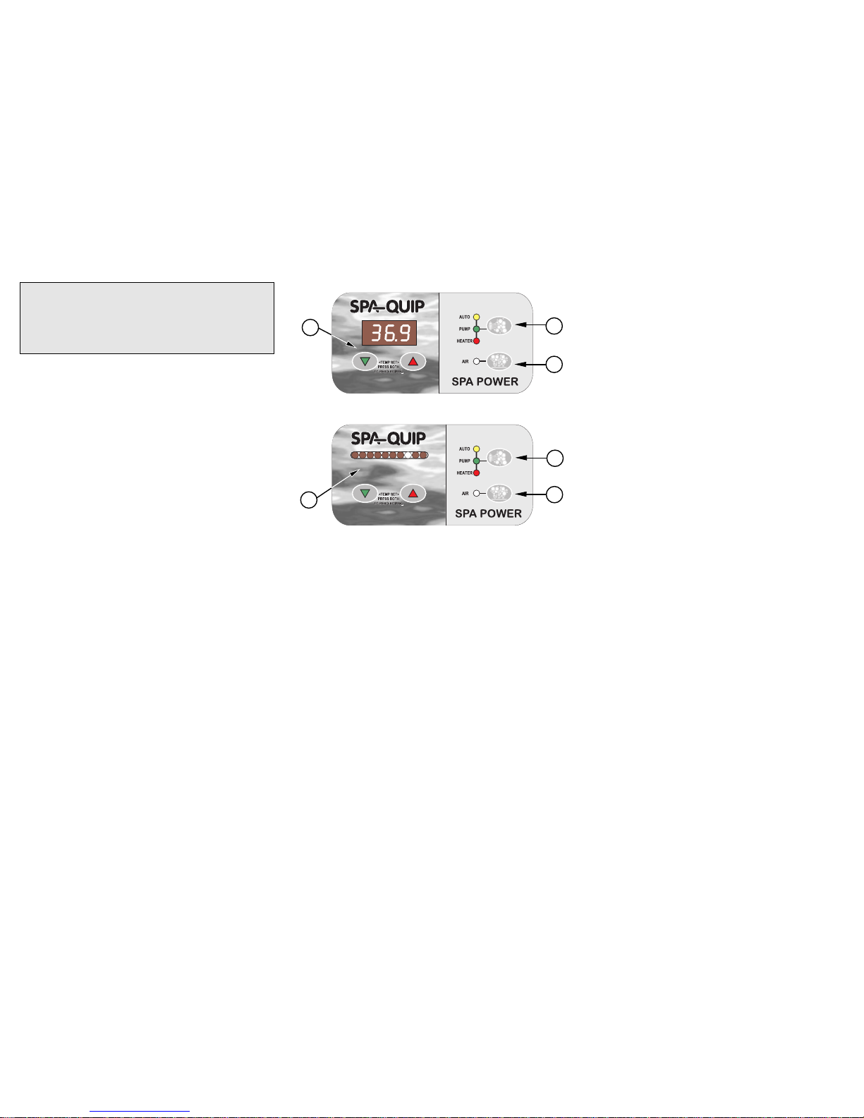
Quick operating instructions:
(1) Pump Mode button
Default state = auto mode on, pump and heater controlled
automatically to maintain pool temperature.
Three pushes on this button cycle the system as follows.
Push 1 = Auto off, pump on, heater automatically
controlled.
Push 2 = Auto off, pump off, heater off.
Push 3 = Auto on, pump and heater controlled
automatically.
(2) Aux/Air/Jets/Light button
Default state = off.
Two pushes of this button cycle the output as follows.
Push 1 = Output on.
Push 2 = Output off.
(3) Temperature setting - Bargraph display
Default setting = 37°C.
Holding down the up or down buttons adjusts the
temperature setting as follows (steady dot).
Up: increases setting 0.5°C per beep, 1.0°C per bargraph
dot.
Down: decreases setting 0.5°C per beep, 1.0°C per
bargraph dot.
Minimum setting = 31°C, maximum setting = 40.5°C.
(4) Temperature setting - Digital display
Default setting = 37°C.
Holding the increase or decrease button down will
automatically adjust the spa temperature setting. This
setting is then displayed on the digital readout.
Up: increases setting 0.5°C per beep.
Down: decreases setting 0.5°C per beep. Minimum
setting = 20°C, maximum setting = 40.5°C.
Clean up cycle:
If desired, a clean up cycle can be initiated after using the
pool so the water is well filtered and brought back up to
temperature if necessary. This is done by simply pushing
the pump mode button so the pump is on and the system
is not in auto mode. This will run the pump for a fixed
period of time (90 minutes) circulating the water through
the filter. The system will then return to auto mode and
maintain the temperature ready for the next time the pool
is used.
Auto Sanitising (filtration):
The Spa Power 500 monitors the amount of pump running
used in normal pool operation. If this is low then it
automatically runs the pump for an additional period to
maintain the filtration/sanitisation of the pool.
Aux/Air/Jets/Light button:
This control gives the user on/off control over an additional
pool accessory which may vary in different pool designs. In
some cases it may not be fitted. Operation is clearly
indicated by a coloured light on the panel. If left on, this
accessory will automatically switch off after a fixed time (30
minutes). Usually switching on this accessory will cause
the heater to switch off (loadshedding). This is in order to
keep the total power load within a safe level.
Up and Down Temperature Control buttons:
The Spa Power 500 gives the user direct control of the pool
temperature from the poolside panel. There is no need to
look under the pool for the temperature adjustment. To
adjust the temperature simply press the up or down
button on the panel until the display corresponds with the
desired temperature. There is a slight delay before the
buttons operate to reduce the risk of accidental
adjustment.
Pushing the Up and Down buttons together produces a
flashing temperature display which indicates the current
sensed temperature in the heater. This is not the pool
temperature, but when the pump is running it should
approximate the pool temperature. The pool temperature
will be maintained very close to the set temperature.
Detailed operating description:
Pump Mode button:
The Spa Power 500 controls the water pump and heater
automatically to maintain the water at the desired
temperature. The user can leave the system to look after
the pool and know it will be at the right temperature
whenever he/she wishes to use it.
The pump mode button allows the user to switch the
pump on or off as desired when using the pool. For safety
the heater is always automatically controlled. Automatic
operation is the default and the system returns to automatic
mode by itself at a fixed time (90 minutes) after the user
last pushed the pump mode button. Pushing the pump
mode button then leaves automatic mode and switches the
pump on. If the pump was already on in auto mode then it
will stay on.
Pushing the pump mode button again will switch the heater
and pump off. The pump will run for a few seconds to cool
the heater before switching off. One more push of the
pump mode button will return to automatic mode. These
operations are clearly indicated on the panel by coloured
lights.
Digital display
Bargraph display
1
2
1
4
3
2
Page 2
Self Diagnostic Error Codes:
The Spa Power 500 controller has extensive self
diagnosing abilities. In the event of a problem it will
indicate an error number according to the nature of the
problem. These are indicated by an alarm beeper beeping
out the error number and by either the bargraph
simultaneously flashing the corresponding dots up to the
error number or the digital display indicating the error
number The error numbers and their meanings are listed
below.
Error 1 (H2O) = PRIME FAILED
Primefailed is a special case. This is not necessarily a
problem with the Spa Power 500 itself, but indicates that no
water is being sensed in the heater. On the push of the
pump mode button the pump will run for 10 seconds to try
get water to the heater. If successful, normal operation will
resume. If unsuccessful Error 1 will be indicated again.
Error 2 = not used.
Errors 3-8 = are fatal errors.
Operation will stop and will not continue until the controller
is reset (switched off and on again at the main power).
Error 3 = STUCK BUTTON
This error indicates that one of the buttons in the control
panel is stuck or has been held down for more that one
minute. This may be caused by water getting into the
panel or by damage to the control panel.
Error 4 = NO WATER SENSOR
This error indicates a problem with the optical water
sensor in the heater. It may also be caused by the sensor
being disconnected inside the unit or by damage to the
sensor.
Error 5 = OVERTEMP
This error indicates that the digital temperature sensor in
the heater has detected a temperature of 45°C or more.
This is not necessarily a problem with the Spa Power 500
itself. It might be caused by excessive pump use during
very hot weather or by disconnection or failure of the pump
(no water flow).
Error 6 = KLIXON TRIPPED
This error indicates that the safety electromechanical over
temperature cut out on the heater has operated. This is
not necessarily a problem with the Spa Power 500 itself. It
might be caused by high temperatures during shipping,
e.g. in the back of a sealed truck, or it might be caused by
disconnection or failure of the pump. This cut out can be
reset by pushing the red reset rod in the controller.
Error 7 = STUCK RELAY
This error indicates a problem with the heater control
circuitry inside the unit.
Error 8 = NO TEMP DATA
This error indicates a problem with the digital temperature
sensor in the heater. It might be caused by the sensor
being disconnected inside the unit or by damage to the
sensor.
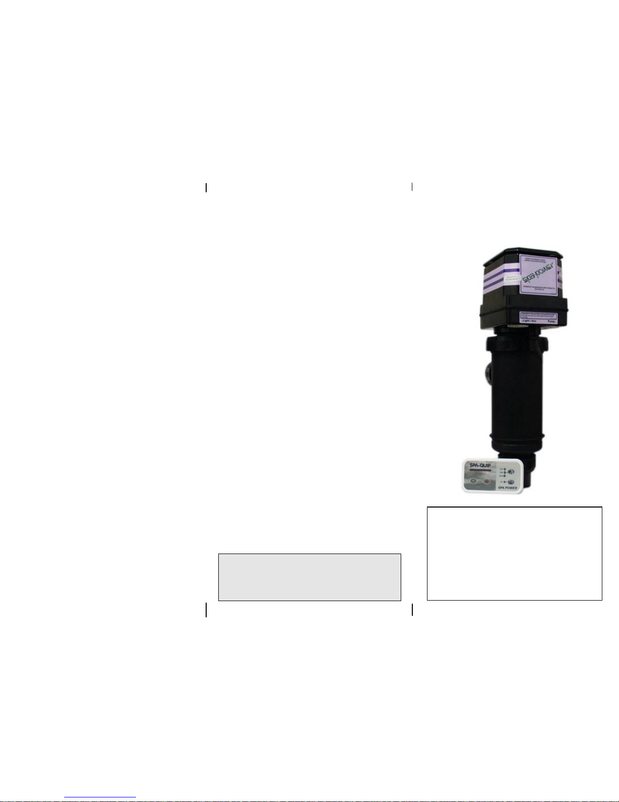
Installation:
1. The heater should be located:
(a) on the pressure side of the pump.
(b) before the filter on the return line and before
chlorinators and ozone injectors (if fitted).
(c) where it is accessible for maintenance and with
enough clear room to remove the control head
from the heater body.
2. The heating system must be installed in an enclosure
rated IP24, ie. it must be totally protected against water
from all directions.
3. All installations must comply with AS3100 and any
additional requirements of your local supply authority
including any relevant code of practice.
4. The heater body may be plumbed so the water can be
in either direction when mounted horizontally. If
mounted horizontally, the heater must be mounted with
its outlet sockets to the top so the safety water
detection circuits are effective. Please note label on
heater head which indicates correct side up.
5. Supply cord damage
If the supply cord of the equipment is damaged, it
must be replaced by a repair shop appointed by the
manufacturer because special purpose tools are
required.
SPA POWER 500
Spa-Quip (Australia) Pty Ltd
Unit 2A, 4 Hudson Ave
Castle Hill, NSW 2154 Australia
Phone: (02) 9634 5600 Fax: (02) 9634 5900
email: service@spa-quip.com.au
Spa-Quip Ltd
PO Box 302-114, North Harbour Post Shop
Auckland New Zealand
Phone: (09) 415 8622 Fax: (09) 415 8621
http://www.spa-quip.co.nz
email: inquiry@spa-quip.co.nz
OPERATING INSTRUCTIONS
Pt No 916309
 Loading...