

Page 1
Manual No. 103-0007
REV. 08/14
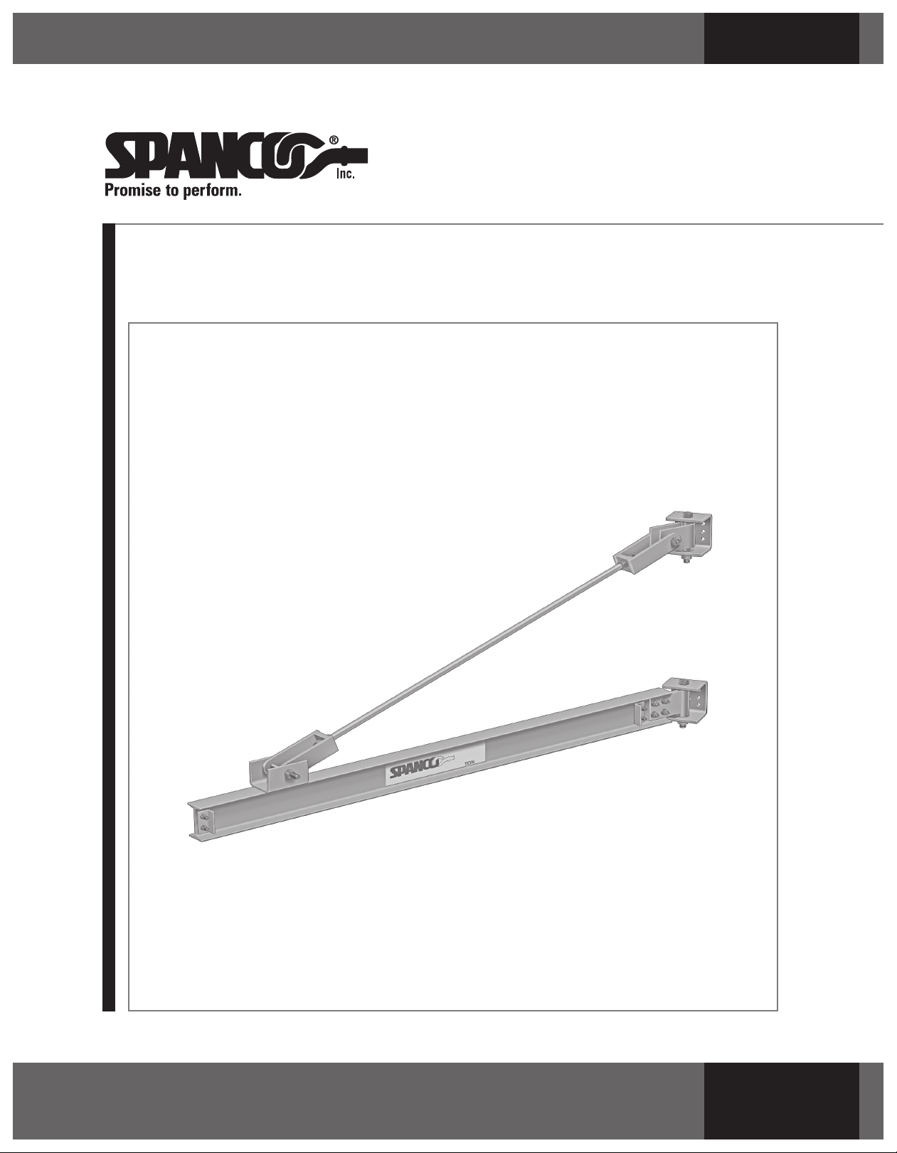
Spare Parts, Instruction and Maintenance Manual for
SPANCO®Model 301 Jib Cranes
ISO 9001 REGISTERED
© Spanco, Inc.
Page 2

2
Page 3

TABLE OF CONTENTS
Forward...................................................................................................................... 4
Installation.............................................................................................................. 4-6
Maintenance...............................................................................................................6
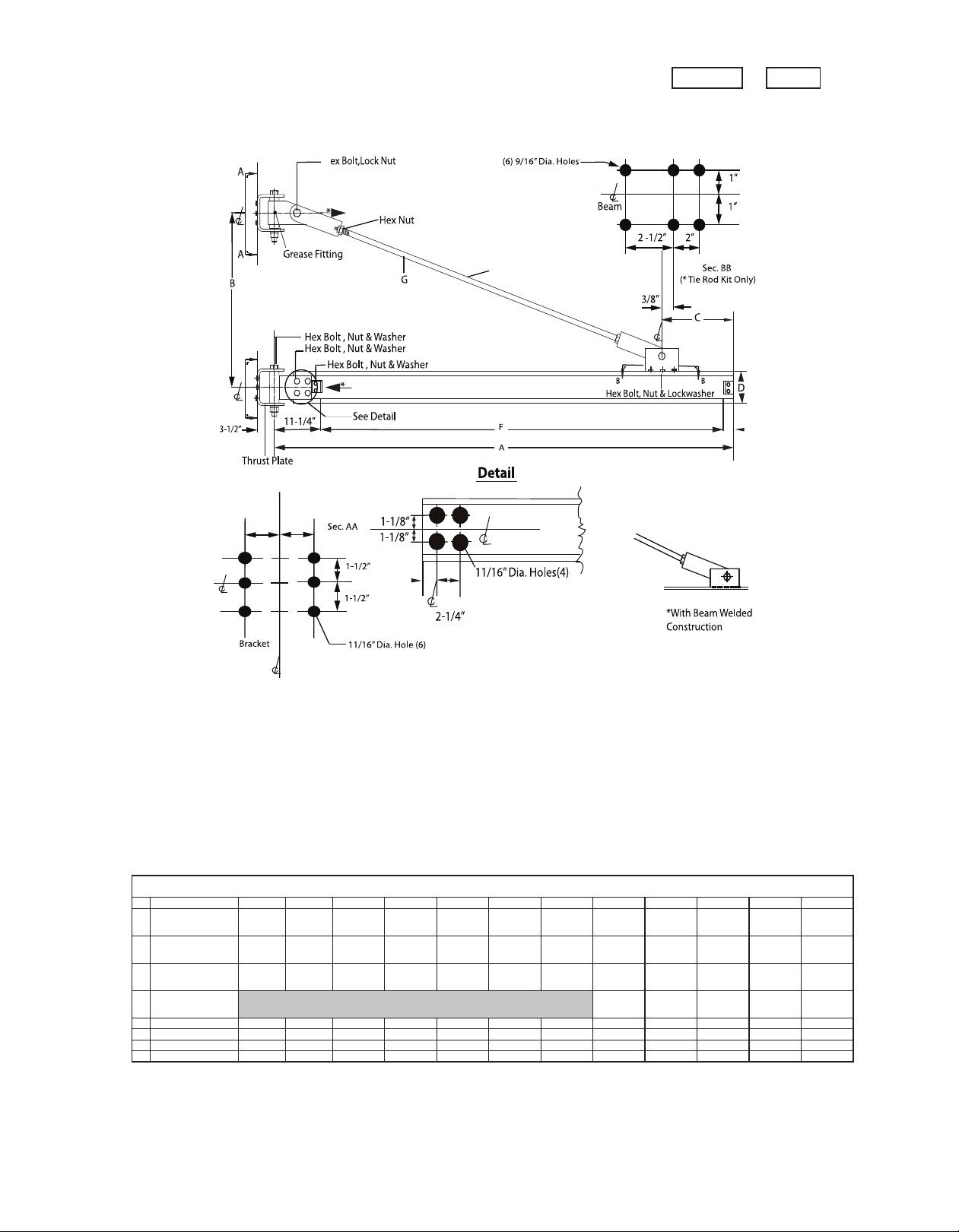
Wall Bracket Jib Crane 200° Rotation Model 301-050................................................... 7
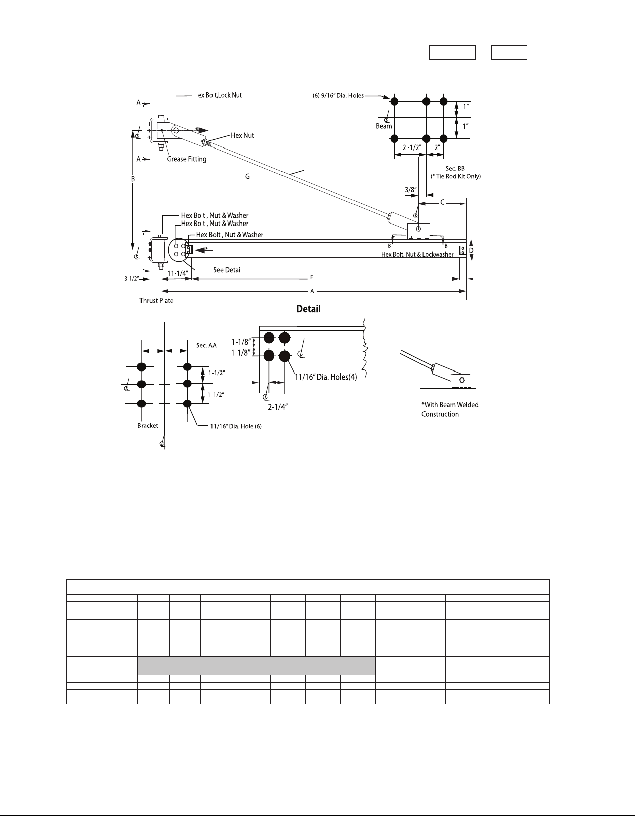
Wall Bracket Jib Crane 200° Rotation Model 301-100................................................... 8
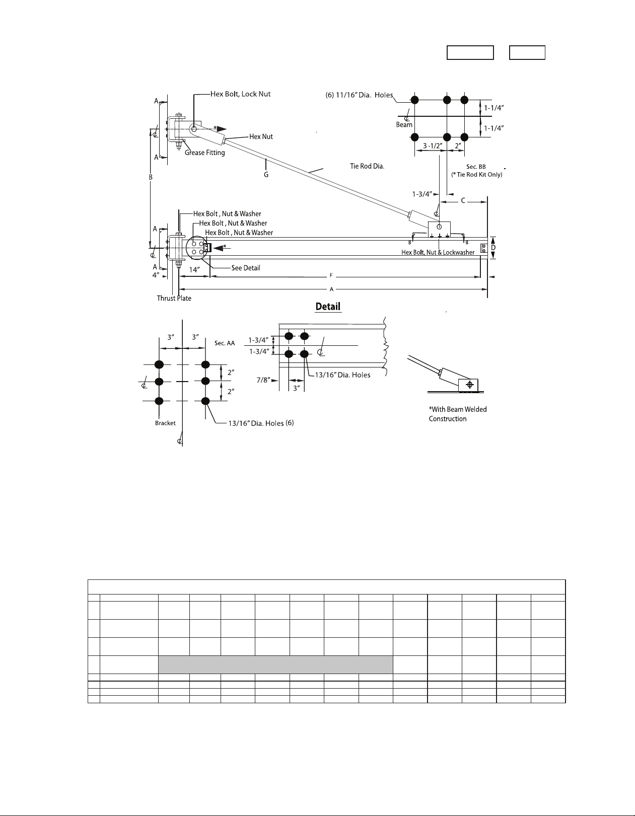
Wall Bracket Jib Crane 200° Rotation Model 301-200................................................... 9
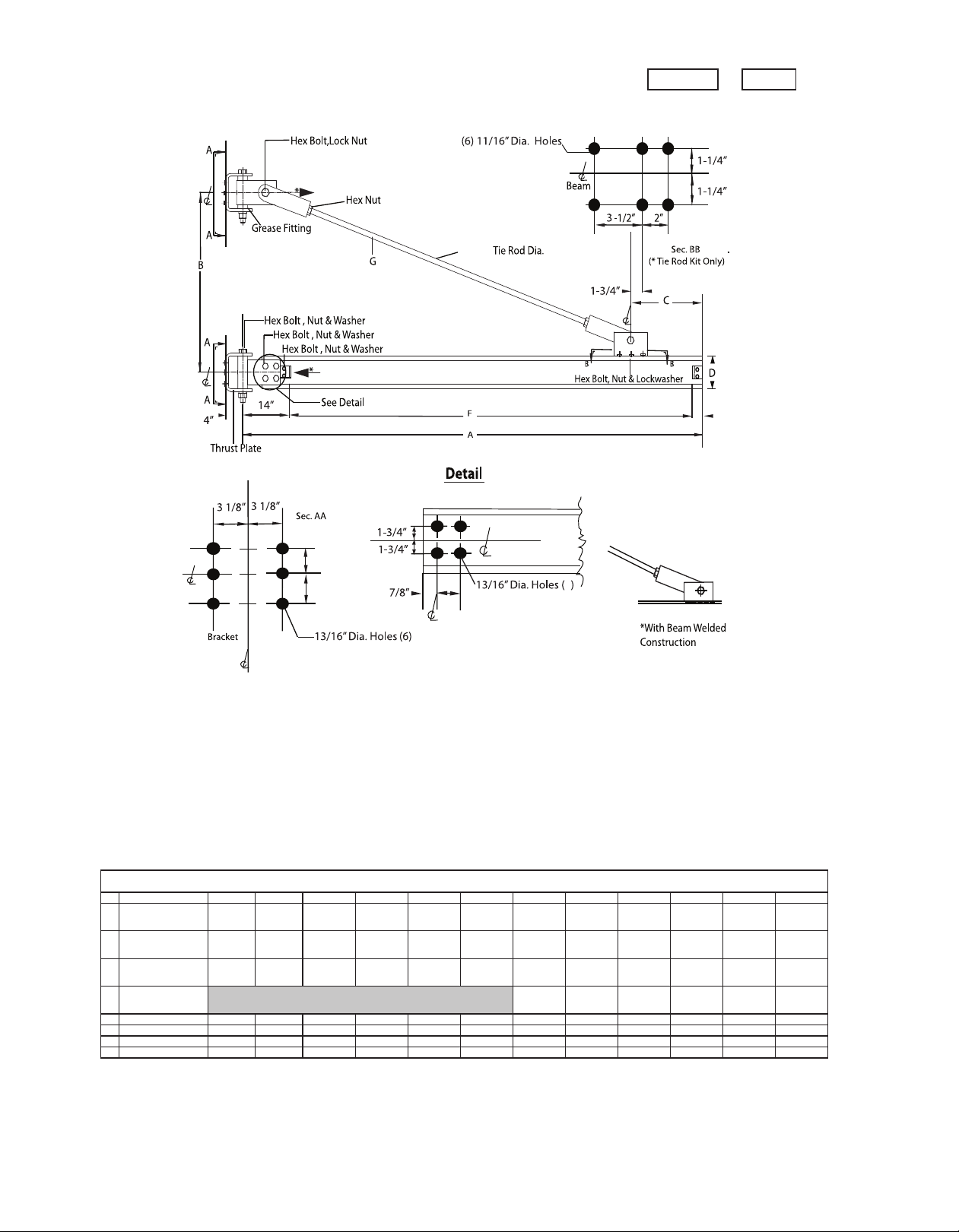
Wall Bracket Jib Crane 200° Rotation Model 301-300................................................. 10
Wall Bracket Jib Crane 200° Rotation Model 301-500................................................. 11
Wall Bracket Model 301-050 to 500 - Exploded View.................................................. 12
Bill of Materials: Wall Bracket (Tie Rod) Jib Crane
Model 301 (050/100)......................................................................................13
Model 301 (200).............................................................................................14
Model 301 (300).............................................................................................15
Model 301 (500).............................................................................................16
Tag Line Support System........................................................................................... 17
Single Position Boom Lock.........................................................................................18
Warranty and Service Policy........................................................................................20
3
Page 4
FORWARD
This manual contains important information to help you install, operate, maintain, and
service your new jib crane. We recommend that you study its contents thoroughly before
putting the jib into use. We also recommend that you obtain the latest issue of ANSI
B30.11 Safety Standard for Monorails and Underhung Cranes and study its contents
thoroughly. By practicing the recommended maintenance suggestions, with proper
installation, and the application of correct operating procedures, you will be assured
maximum service from your jib crane.
The jibs described in this manual are intended for indoor service. Jib cranes used for outdoor
service require special consideration.
INSTALLATION
Before attempting to install your new jib crane, the following items must be understood:
1. It is the customer’s responsibility to ensure that building columns or walls are adequate
to support the crane and its rated load.
2. Jib cranes should not be hung from an existing building structure without first
consulting a qualified architect or engineer for the purpose of determining the
structure’s adequacy.
NOTE: DO NOT MOUNT THE JIB CRANE TO ANY STRUCTURE UNLESS YOU
ARE SURE THE STRUCTURE CAN SAFELY SUPPORT THE LOADS IMPOSED
UPON THE STRUCTURE. FAILURE TO CHECK THIS ITEM CAN RESULT IN
SEVERE BODILY INJURY OR DEATH.
3. The installer is responsible for supplying the correct size, length, number, and type of
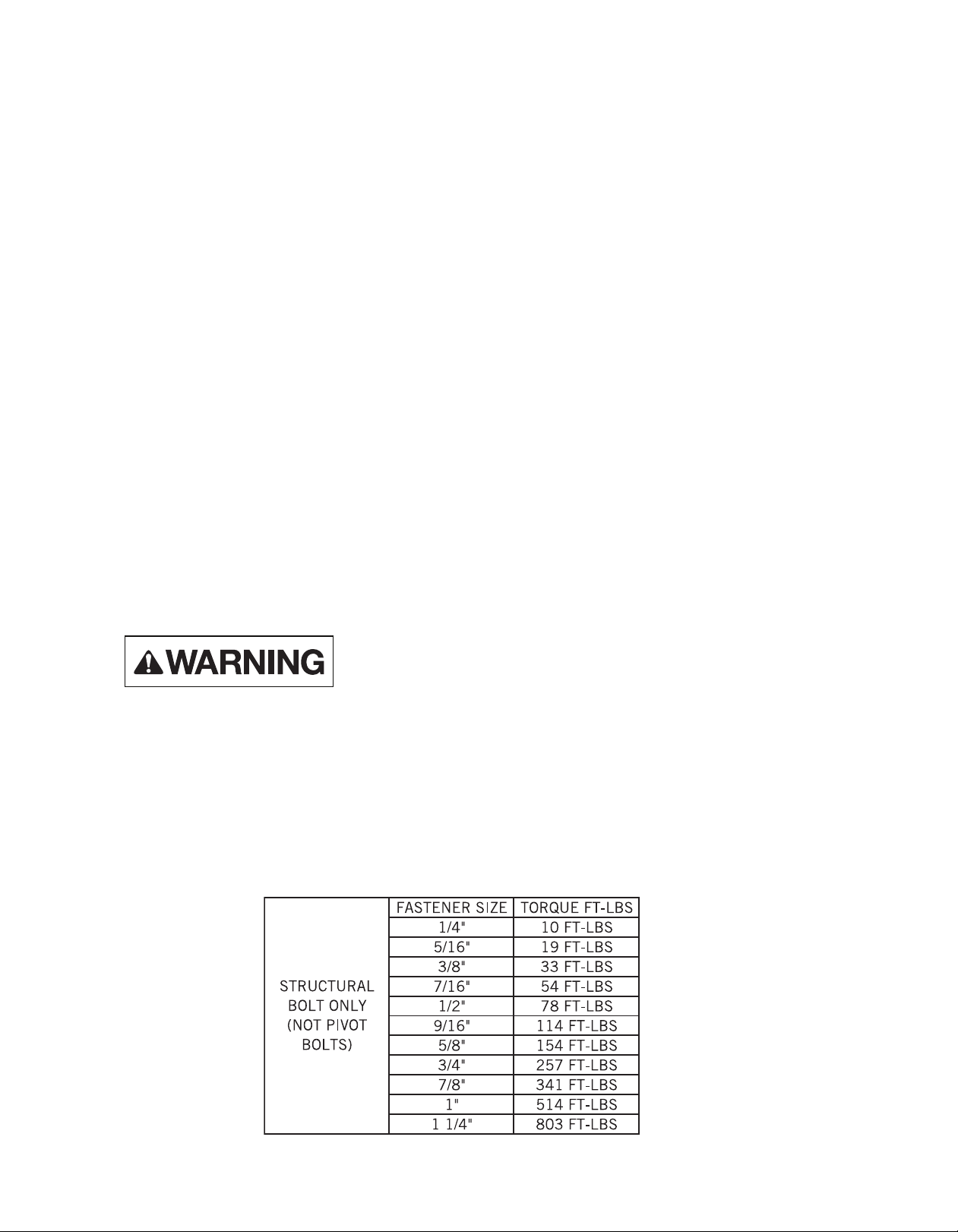
bolts required to attach the jib crane brackets to the structure. SPANCO recommends
that the bolts be ASTM A325 grade.
4. Plan the installation such that the proper clearance as outlined in ANSI B30.11 will be
adhered to. In the design of jib crane systems, all factors that influence clearances,
such as roof truss sag, and boom deflection shall be considered.
4
Page 5
After these points have been covered, you may begin the installation procedure as follows:
1. Refer to the appropriate table in this manual and locate the dimensions of the specific Model
301 jib crane to be installed.
2. Determine the elevation of the top wall bracket by adding the “Bracket Centers” dimension to
the desired elevation of the bottom of the boom plus 1/2 the boom height.
3. Hold the top wall bracket against the supporting column in its proper location with a C-clamp or
other supporting method.
4. Establish the correct distance from the top wall bracket to the bottom wall bracket from
the charts (“Dimension B”). Hold the bottom wall bracket against the supporting column with a
C-clamp or other supporting method.
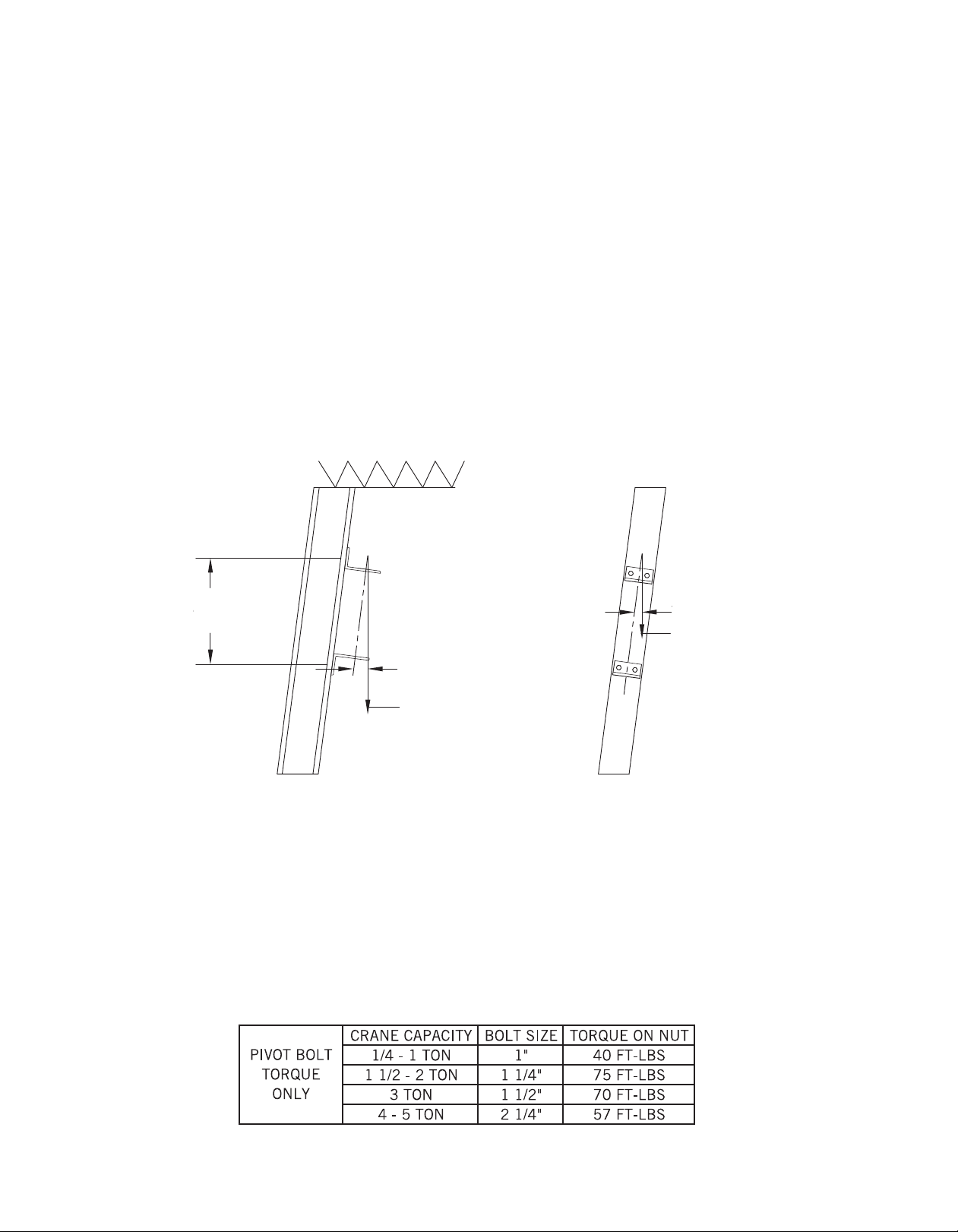
5. Use a plumb bob to check the alignment of the bottom bracket with the top bracket in two
planes. The alignment must be within 1/16 inches from top to bottom.
SIDE VIEW FRONT VIEW
Dimension B
1/16” MAX
PLUMB BOB
1/16” MAX
PLUMB BOB
6. Using the wall brackets as a template, mark the established hole locations.
7. Drill the holes in the column for the wall brackets.
8. Mount the wall brackets and their shims (if used) to the column with bolts (ASTM A-325)
supplied by the installer. Care should be taken to insure all bolts are properly tightened.
9. Lift the boom assembly with its brackets and tie rod assembly attached with a lift truck or other
means into place. Insert the top pivot assembly and the bottom pivot assembly into its
respective wall brackets. Insert the top and bottom bracket bolts into the bracket assemblies
and properly tighten the nuts to the torque listed.
5
Page 6
10. Remove the end stop angles from the boom tip and install the hoist and trolley onto the boom.
Refer to the hoist manufacturer’s manual for proper setting of the trolley wheels to match the
boom beam. Remember to reinstall the end stop angles on the boom and properly tighten the
nuts after installation of the hoist trolley on the jib.
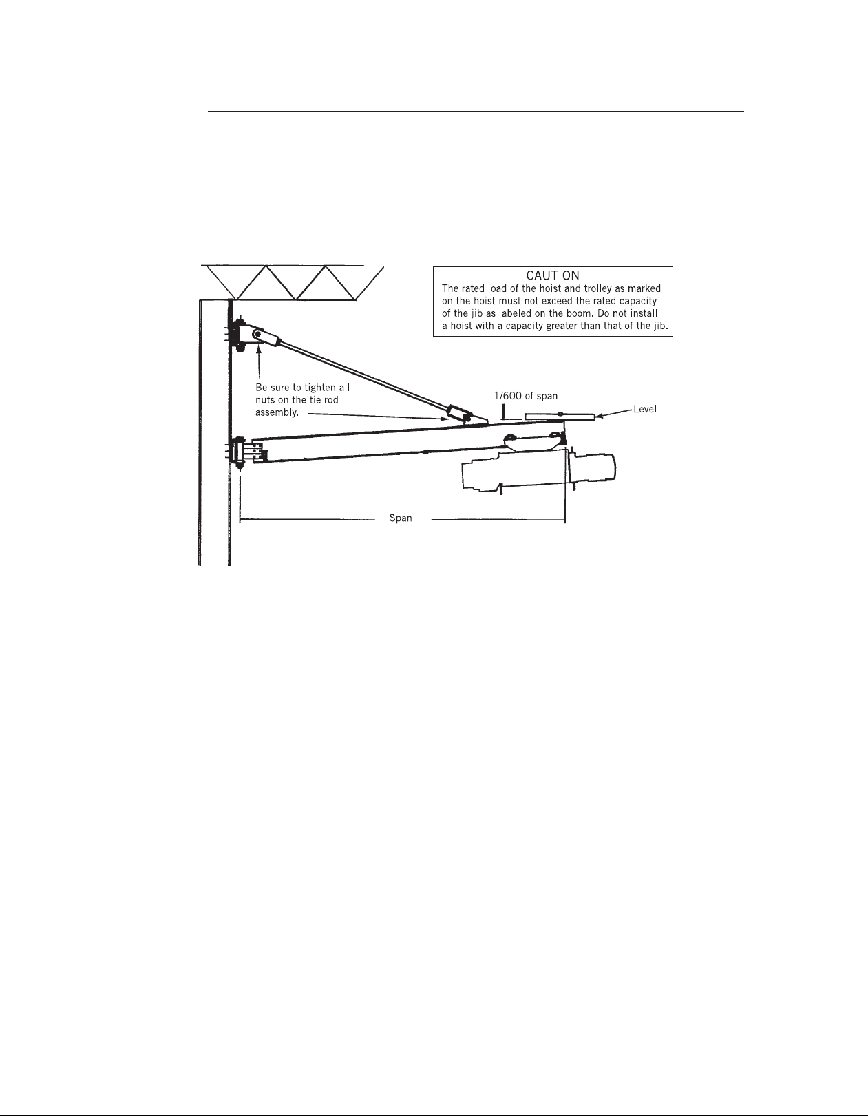
11. Position the unloaded hoist and trolley at the extreme tip of the boom and adjust the tie rod
assembly deflection, the boom tip should be adjusted to an elevation equal to
boom length (inches) ÷ 600 above level.
12. Connect the hoist to its source of power (either air or electric) if required, as per the hoist
manufacturer’s manual.
13. Now that the jib crane installation is complete, but before the unit is placed into service, it is
important to review and follow procedures outlined in Chapter 11-2 of ANSI B30.11 regarding
inspection, testing, and maintenance.
MAINTENANCE
By definition, the term “jib crane” includes the jib, the trolley, and the hoist, along with any
attachment that may exist. The user should refer to the manual supplied with the hoist and trolley
for a listing of maintenance points and their suggested frequency.
With regards to the SPANCO jib, the only maintenance item is that of the wall bracket lubrication.
The sleeve bearings in those brackets are pre-lubricated at the factory. Field lubrication of those
bearings is required based upon usage of the crane. SPANCO recommends that the bearings be
lubricated at least once a year. The grease should be a lithium soap based grease, consistency
No. NLGI 2.
6
Page 7
1” Dia. Tie Rod
1-3/4” 1-3/4”
Thrust
Pull
H
2-1/2”
3/4”3/4”
A
SPAN
81012 14 16 18 20 22 24 26 28 30
B
WALL BRACKET
CENTER
2'-9" 3'-0" 3'-9" 4'-6" 5'-6" 6'-0" 6'-6" 7'-0" 7'-6" 8'-0" 9'-0" 10'-0"
C
BEAM BRACKET
CENTER
1'-3" 1'-6" 1'-9" 2'-0" 2'-0" 2'-0" 2'-3" 2'-3" 2'-6" 2'-6" 3'-0" 3'-6"
BEAM
66 6 6 6 8 101010101212
WGT/FT.
12.5# 12.5# 12.5# 12.5# 12.5# 18.4# 25.4# 25.4# 25.4# 25.4# 31.8# 31.8#
CAP CHANNEL
88888
WGT/FT.
11.5# 11.5# 11.5# 11.5# 11.5#
F
CLEAR SPAN
6'-9 3/4" 8'-9 3/4" 10'-9 3/4" 12'-9 3/4" 14'-9 3/4" 16'-9 3/4" 18'-9 3/4" 20'-9 3/4" 22'-9 3/4" 24'-9 3/4" 26'-9 3/4" 28'-9 3/4"
G
TIE ROD LENGTH
5'-7" 7'-4" 9'-5" 11'-2" 13'-4" 15'-5" 17'-2" 19'-3" 21'-1" 23'-1" 25'-1" 26'-7"
*
THRUST/PULL
3710 4790 4350 4320 4110 4380 4660 5120 5320 5800 5670 6010
**
WEIGHT
192# 222# 253# 283# 314# 449# 489# 619# 739# 914# 986# 1407#
1/2 TON
301 SERIES WALL BRACKET
D
E
WALL BRACKET JIB CRANE 200º ROTATION MODEL 301 - 050 -
1/2 TON CAPACITY
7
Page 8
1” Dia. Tie Rod
1-3/4” 1-3/4”
Thrust
P
ull
H
2-1/2”
3/4”3/4”
A
SPAN
81012 14 16 18 20 22 24 26 28 30
B
WALL BRACKET
CENTER
2'-9" 3'-0" 3'-9" 4'-6" 5'-6" 6'-0" 6'-6" 7'-0" 7'-6" 8'-0" 9'-0" 10'-0"
C
BEAM BRACKET
CENTER
1'-3" 1'-6" 1'-9" 2'-0" 2'-3" 2'-6" 2'-6" 2'-9" 3'-9" 3'-0" 3'-6" 3' -6"
BEAM
66 6 8 8 8 101010101212
WGT/FT.
12.5# 12.5# 12.5# 18.4# 18.4# 18.4# 25.4# 25.4# 25.4# 25.4# 31.8# 31.8#
CAP CHANNEL
88888
WGT/FT.
11.5# 11.5# 11.5# 11.5# 11.5#
F
CLEAR SPAN
6'-10 3/4" 8'-10 3/4" 10'-10 3/4" 12'-10 3/4" 14'-10 3/4" 16'-10 3/4" 18'-10 3/4" 20'-10 3/4" 22'-10 3/4" 24'-10 3/4" 26'-10 3/4" 28'-10 3/4"
G
TIE ROD LENGTH
5'-7" 7'-4" 9'-5" 11'-2" 13'-4" 14'-11" 16'-11" 19'-1" 20' 22'-7" 24'-4" 26'-7"
*
THRUST/PULL
7280 8610 8460 8430 8000 8430 8970 9570 9880 10,170 10,290 10,070
**
WEIGHT
192# 222# 253# 283# 406# 449# 627# 832# 902# 976# 1291# 1407#
301 SERIES WALL BRACKET
D
E
1 TON
WALL BRACKET JIB CRANE 200º ROTATION MODEL 301 - 100 -
1 TON CAPACITY
8
Page 9
1-1/2”
(4)
Thrust
Pull
2-1/2”
A
SPAN
81012 14 16 18 20 22 24 26 28 30
B
WALL BRACKET
CENTER
2'-9" 3'-0" 3'-9" 4'-6" 5'-6" 6'-0" 6'-6" 7'-0" 7'-6" 8'-0" 9'-0" 10'-0"
C
BEAM BRACKET
CENTER
1'-3" 1'-6" 1'-9" 2'-0" 2'-3" 2'-3" 2'-6" 2'-6" 3'-6" 3'-6" 3'-6" 3'-0"
BEAM
88 8 8 1010121212121212
WGT/FT.
18.4# 18.4# 18.4# 18.4# 25.4# 25.4# 31.8# 31.8# 31.8# 31.8# 31.8# 31.8#
CAP CHANNEL
88888
WGT/FT.
11.5# 11.5# 11.5# 11.5# 11.5#
F
CLEAR SPAN
6'-7-1/2" 8'-7-1/2" 10'-7-1/2" 12'-7-1/2" 14'-7-1/2" 16'-7-1/2" 18'-7-1/2" 20'-7-1/2" 22'-7-1/2" 24'-7-1/2" 26'-7-1/2" 28'-7-1/2"
G
TIE ROD LENGTH
5'-11"7'-8" 9'-6" 11'-5" 13'-4" 15'-5" 17'-2" 19'-3" 20'-0" 22'-7" 24'-10" 27'-4"
*
THRUST/PULL
14,470 17,110 16,780 16,580 15,870 16,560 17,350 18,300 18,840 19,330 18,690 18,190
**
WEIGHT
305# 352# 401# 449# 604# 667# 854# 1127# 1220# 1323# 1424# 1526#
D
E
2 TON
301 SERIES WALL BRACKET
WALL BRACKET JIB CRANE 200º ROTATION MODEL 301 - 200 -
2 TON CAPACITY
9
Page 10
1-1/2”
3”
2-1/2”
Pull
Thrust
4
2-1/2”
2-1/2”
A
SPAN
81012 14 16 18 20 22 24 26 28 30
B
WALL BRACKET
CENTER
2'-9" 3'-3" 4'-0" 4'-9" 5'-6" 6'-3" 7'-0" 7'-9" 8'-6" 9'-3" 10'-0" 11'-0"
C
BEAM BRACKET
CENTER
1'-3" 1'-6" 1'-9" 2'-0" 2'-3" 2'-3" 2'-6" 2'-6" 3'-6" 3'-0" 3'-0" 3'-0"
BEAM
8810101012 121212121212
WGT/FT.
18.4# 18.4# 25.4# 25.4# 25.4# 31.8# 31.8# 31.8# 31.8# 31.8# 31.8# 31.8#
CAP CHANNEL
888888
WGT/FT.
11.5# 11.5# 11.5# 11.5# 11.5# 11.5#
F
CLEAR SPAN
6'-8" 8'-8" 10'-8" 12'-8" 14'-8" 16'-8" 18'-8" 20'-8" 22'-8" 24'-8" 26'-8" 28'-8"
G
TIE ROD LENGTH
5'-2" 7'-0" 8'-10" 10'-9" 12'-7" 14'-9" 16'-8" 18'-9" 20'-0" 22'-6" 24'-8" 26'-11"
*
THRUST/PULL
21,600 23,550 23,560 23,520 23,500 23,680 24,040 24,120 24,200 24,290 24,380 23,920
**
WEIGHT
395# 444# 572# 635# 701# 689# 1147# 1246# 1341# 1443# 1542# 1643#
D
3 TON
E
301 SERIES WALL BRACKET
WALL BRACKET JIB CRANE 200º ROTATION MODEL 301 - 300 -
3 TON CAPACITY
10
Page 11
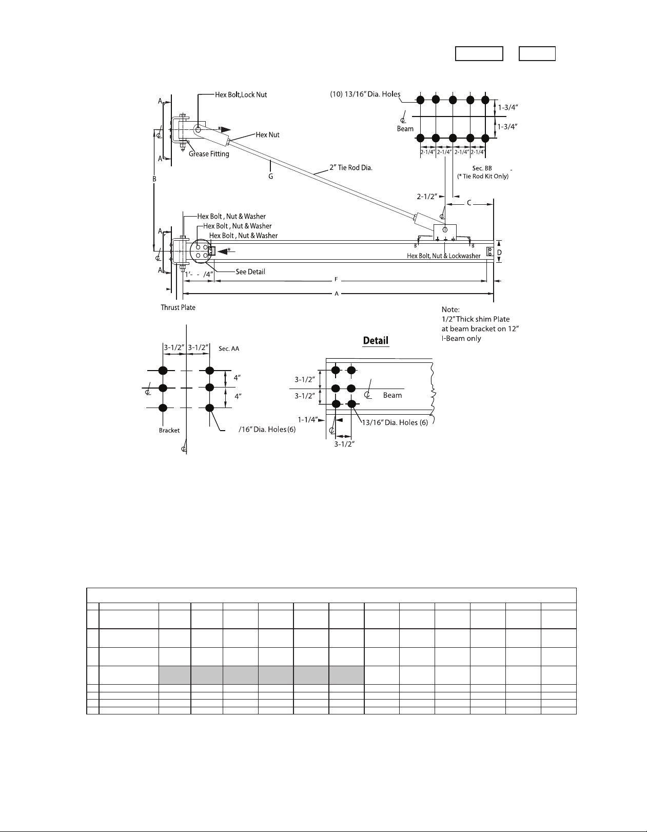
5
2-1/2”
Pull
T
hrust
4
6-1/2”
1-
3
A
SPAN
81012 14 16 18 20 22 24 26 28 30
B
WALL BRACKET
CENTER
3'-0" 3'-3" 4'-0" 4'-9" 5'-6" 6'-3" 7'-0" 7'-9" 8'-6" 9'3" 10'-0" 11'-0"
C
BEAM BRACKET
CENTER
1'-6" 1'-6" 1'-9" 2'-0" 2'-6" 3'-0" 3'-6" 3'-6" 3'-6" 3'-6" 3'-6" 3'-6"
BEAM
12 12 12 12 15 15 15 15 15 15 15 15
WGT/FT.
31.8# 31.8# 31.8# 31.8# 42.9# 42.9# 42.9# 42.9# 42.9# 42.9# 42.9# 42.9#
CAP CHANNEL
10 10 10 10 10 10
WGT/FT.
15.3# 15.3# 15.3# 15.3# 15.3# 15.3#
F
CLEAR SPAN
6'-4 3/4" 8'-4 3/4" 10'-4 3/4" 12'-4 3/4" 14'-4 1/4" 16'-4 1/4" 18'-4 1/4" 20'-4 1/4" 22'-4 1/4" 24'-4 1/4" 26'-4 1/4" 28'-4 1/4"
G
TIE ROD LENGTH
4'-6" 6'-5" 8'-4" 10'-3" 11'-10" 13'-6" 15'-2" 17'-4" 19'-6" 21'-7" 23'-9" 25'-11"
*
THRUST/PULL
33,010 39,260 39,070 38,980 39,180 39,190 39,670 39,760 38,960 39,970 40,080 39,290
**
WEIGHT
972# 1058# 1144# 1230# 1478# 1582# 1951# 2089# 2227# 2365# 2503# 2641#
301 SERIES WALL BRACKET
D
E
5 TON
WALL BRACKET JIB CRANE 200º ROTATION MODEL 301 - 500 -
5 TON CAPACITY
11
Page 12
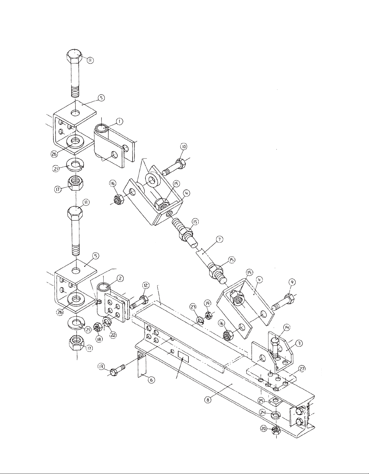
WALL BRACKET MODEL 301-050 to 500
Exploded View
5 TON ONLY
GREASE FITTING
BEAM CAPPED
WHEN REQUIRED
5 TON ONLY
WHEN REQUIRED
Serial Number
Location
starting
12/03
12
Page 13
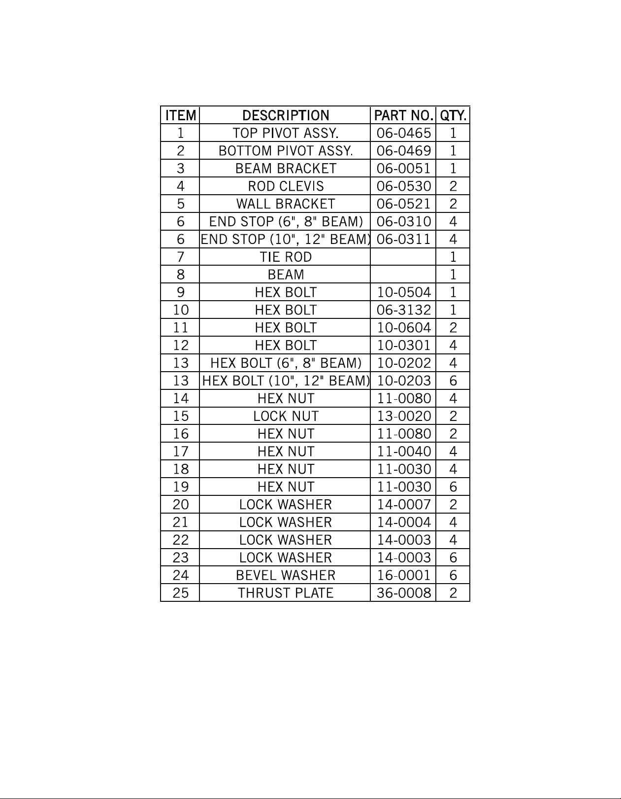
BILL OF MATERIALS
WALL BRACKET (TIE ROD) JIB CRANE
MODEL 301 (050/100)
Ordering Repair Parts
When ordering repair parts from this manual, be sure to state the model and serial number
of the unit. This information can be found on the small metal plate attached to the jib crane.
The hardware kits are determined by the capacity of the jib crane.
Hardware
Model 301 (050/100)
13
1/2 and 1 Ton Capacity
Page 14
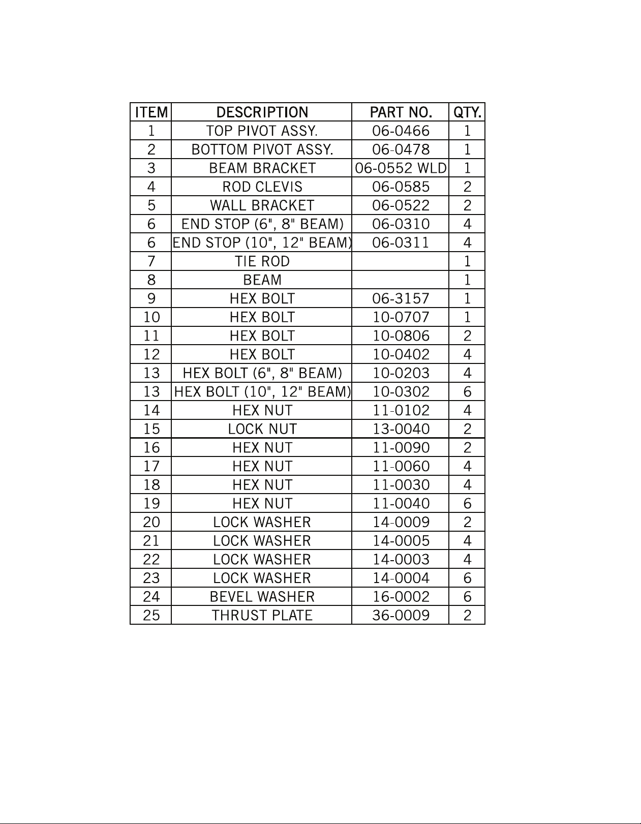
BILL OF MATERIALS
WALL BRACKET (TIE ROD) JIB CRANE
MODEL 301 (200)
Ordering Repair Parts
When ordering repair parts from this manual, be sure to state the model and serial number
of the unit. This information can be found on the small metal plate attached to the jib crane.
The hardware kits are determined by the capacity of the jib crane.
Hardware
Model 301 (200) 2 Ton Capacity
14
Page 15
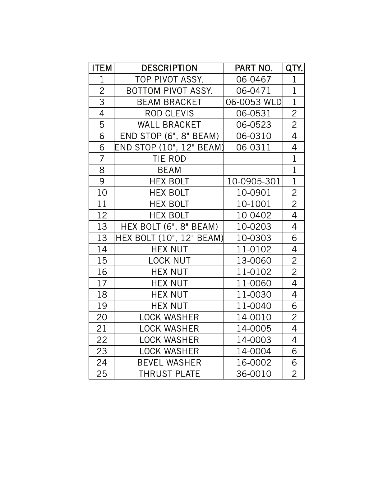
BILL OF MATERIALS
WALL BRACKET (TIE ROD) JIB CRANE
MODEL 301 (300)
Ordering Repair Parts
When ordering repair parts from this manual, be sure to state the model and serial number
of the unit. This information can be found on the small metal plate attached to the jib crane.
The hardware kits are determined by the capacity of the jib crane.
Hardware
Model 301 (300) 3 Ton Capacity
15
Page 16
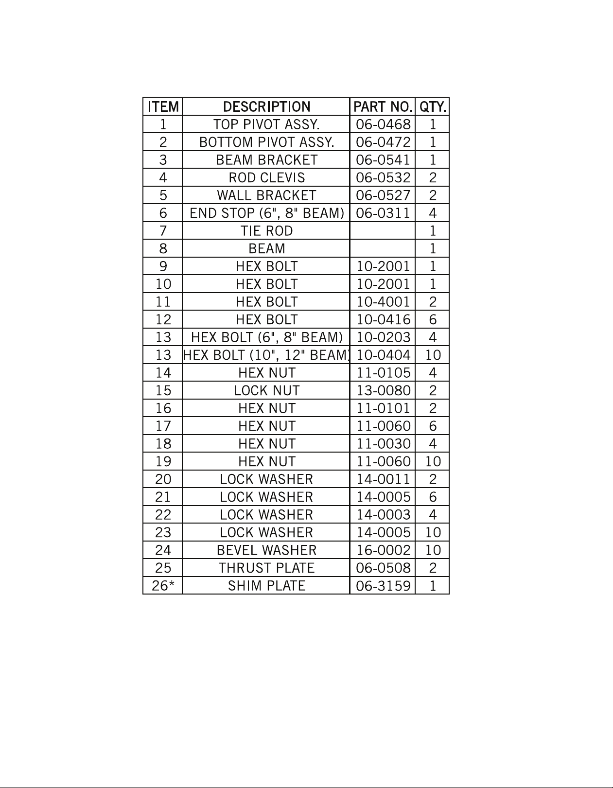
BILL OF MATERIALS
WALL BRACKET (TIE ROD) JIB CRANE
MODEL 301 (500)
Ordering Repair Parts
When ordering repair parts from this manual, be sure to state the model and serial number
of the unit. This information can be found on the small metal plate attached to the jib crane.
The hardware kits are determined by the capacity of the jib crane.
Hardware
Model 301 (500) 5 Ton Capacity
16
Page 17
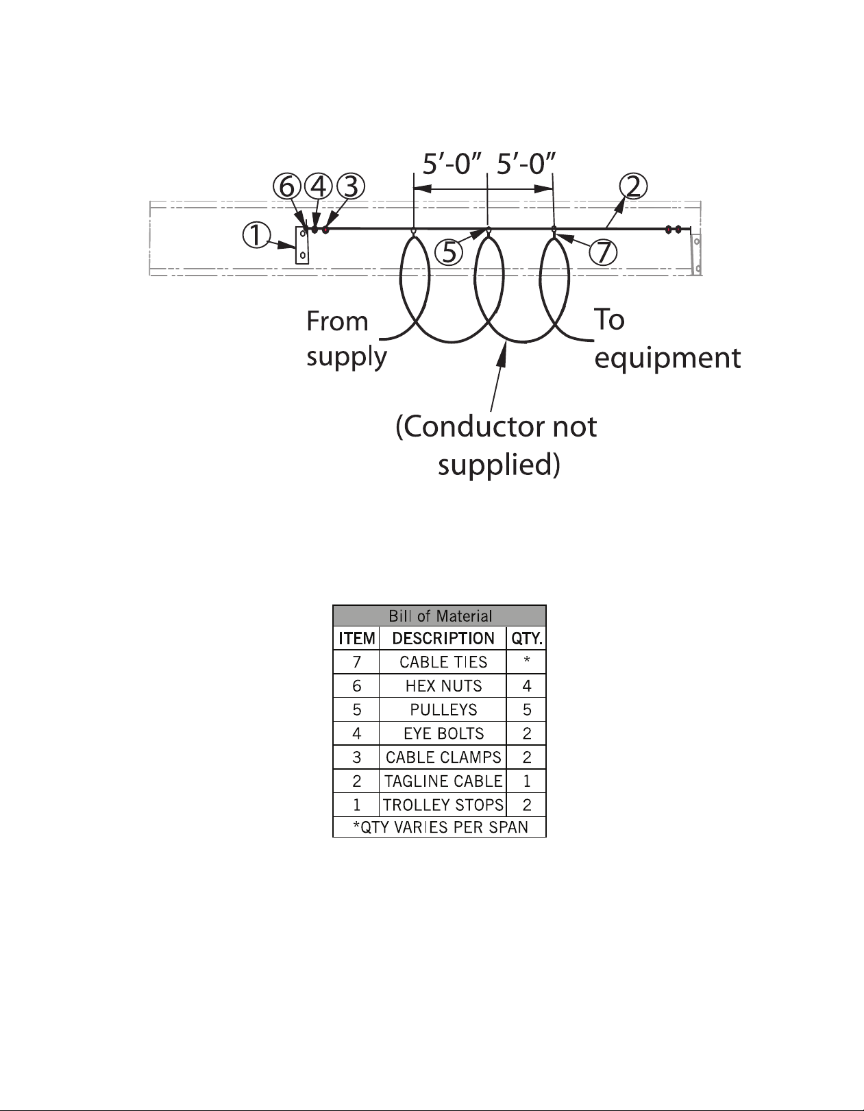
TAG LINE SUPPORT SYSTEM
17
Page 18
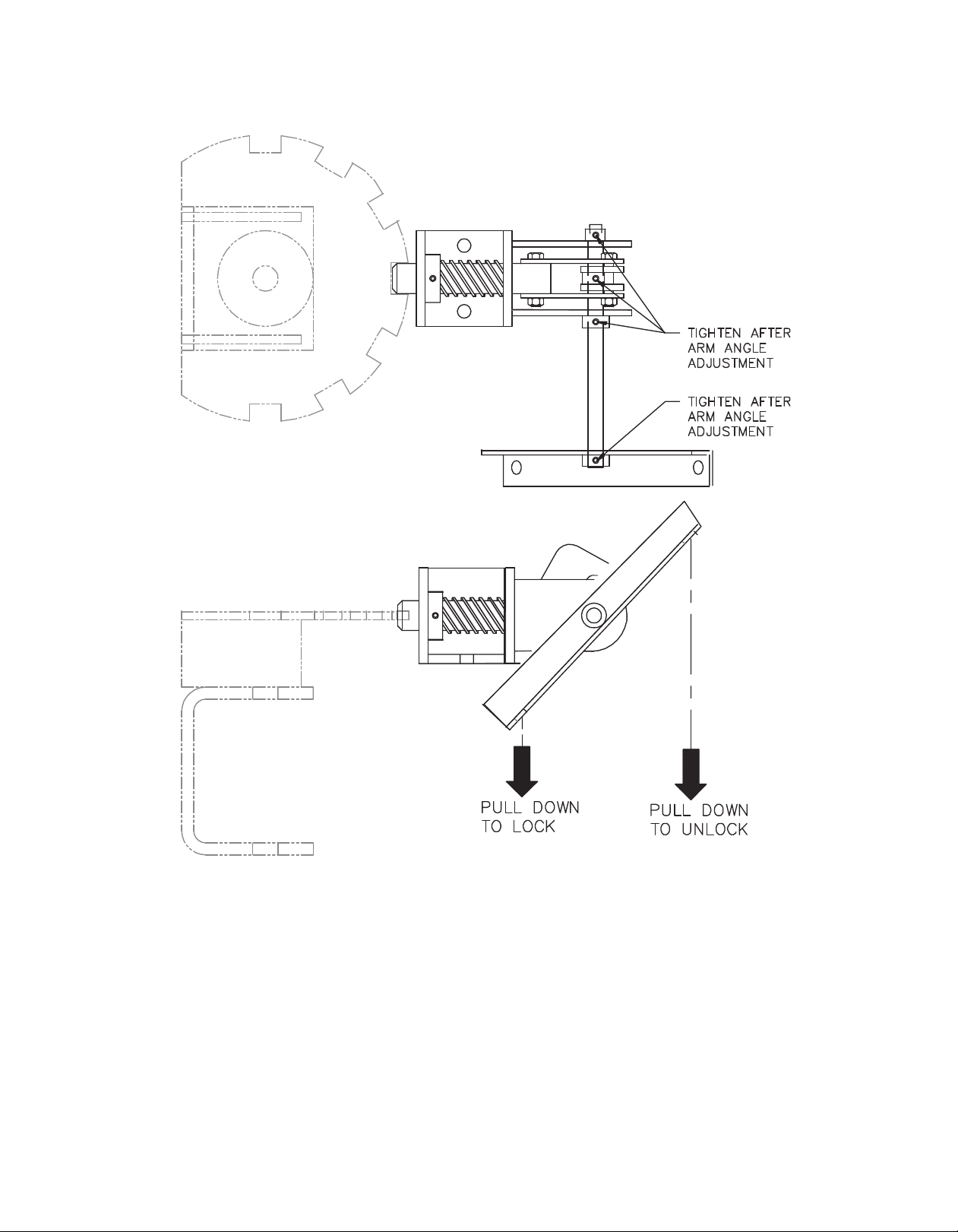
SINGLE POSITION BOOM LOCK
NOTE:
1. Rope length must be specified to fit each crane. To determine rope length use: 2 X floor
to height under boom minus 7’-0”. This will place rope approximately 3’-6” from floor.
2. Thread roped ends through holes and tie knots at rope ends.
3. To adjust swing-arm, all set screws and collers should be loose to return components to
the proper position. Push main locking pin against bottom of slot and make sure lever
arm is horizontal. Tighen all set screws to anchor set screws in shaft.
18
Page 19

19
Page 20

Spanco, Inc.
604 Hemlock Road
Morgantown, PA, 19543
Toll Free: 800-869-2080
Local: 610-286-7200
Fax: 610-286-0085
Spanco.com
TEN-YEAR SPANCO WARRANTY
Products covered under the Ten-Year Warranty:
• Manual Steel Freestanding, Ceiling Mounted Workstation Bridge Cranes, and Monorails
• Manual Aluminum (Alu-Track®) Workstation Bridge Cranes and Monorails
• Manual Jib Cranes (I-Beam, Articulating, and Workstation Jib Cranes)
• Manual Gantry Cranes and Tripods
What the Ten-Year Warranty covers:
• Defects in Equipment material and workmanship
• Wearable parts (end truck and hoist trolley wheels only)
Spanco, Inc. warrants its manual workstation bridge crane products, jib crane products, and gantry crane products
to be free from defects in material and workmanship for a period of ten (10) years or 20,000 hours, commencing
on the date of shipment to the first retail purchaser. This warranty extends to non-wearable parts only, with the
exception of the wheels supplied on manually operated workstation end trucks and hoist trolleys. This warranty
does not cover defective equipment or system failure caused by misuse, negligence, improper installation or
maintenance, or equipment that has been used in excess of its rated capacity or beyond its service factors. It
does not apply to equipment that has been altered without Spanco’s written authorization.
Written notice of any claimed system defect must be given to Spanco within thirty days of discovery. Spanco's
obligation under this warranty is limited to the replacement or repair of Spanco’s products at the factory or
separate location approved by Spanco. The purchaser is responsible for all freight and transportation costs relating
to equipment repair or replacement. Other than the abovementioned warranty, Spanco will not honor any other
warranties—whether express, implied, or statutory—and disclaims any warranties of merchantability or fitness for a
particular purpose. Spanco is not liable—under any circumstances—for any indirect, incidental, or consequential
damages including but not limited to lost profits, increased operating costs, or loss of production.
This warranty does not extend to components or accessories not manufactured by Spanco. The purchaser’s remedy
for such components and accessories will be determined by the terms and conditions of any the warranty provided
by the manufacturer of such components and accessories.
NOTE: All motorized Spanco products come with a One-Year Warranty on drive components.
20
 Loading...