

SPAL SHAVED-40 Installation Manual And Operating Instructions
SHAVED-40
INSTALLATION MANUAL & OPERATION INSTRUCTIONS
®
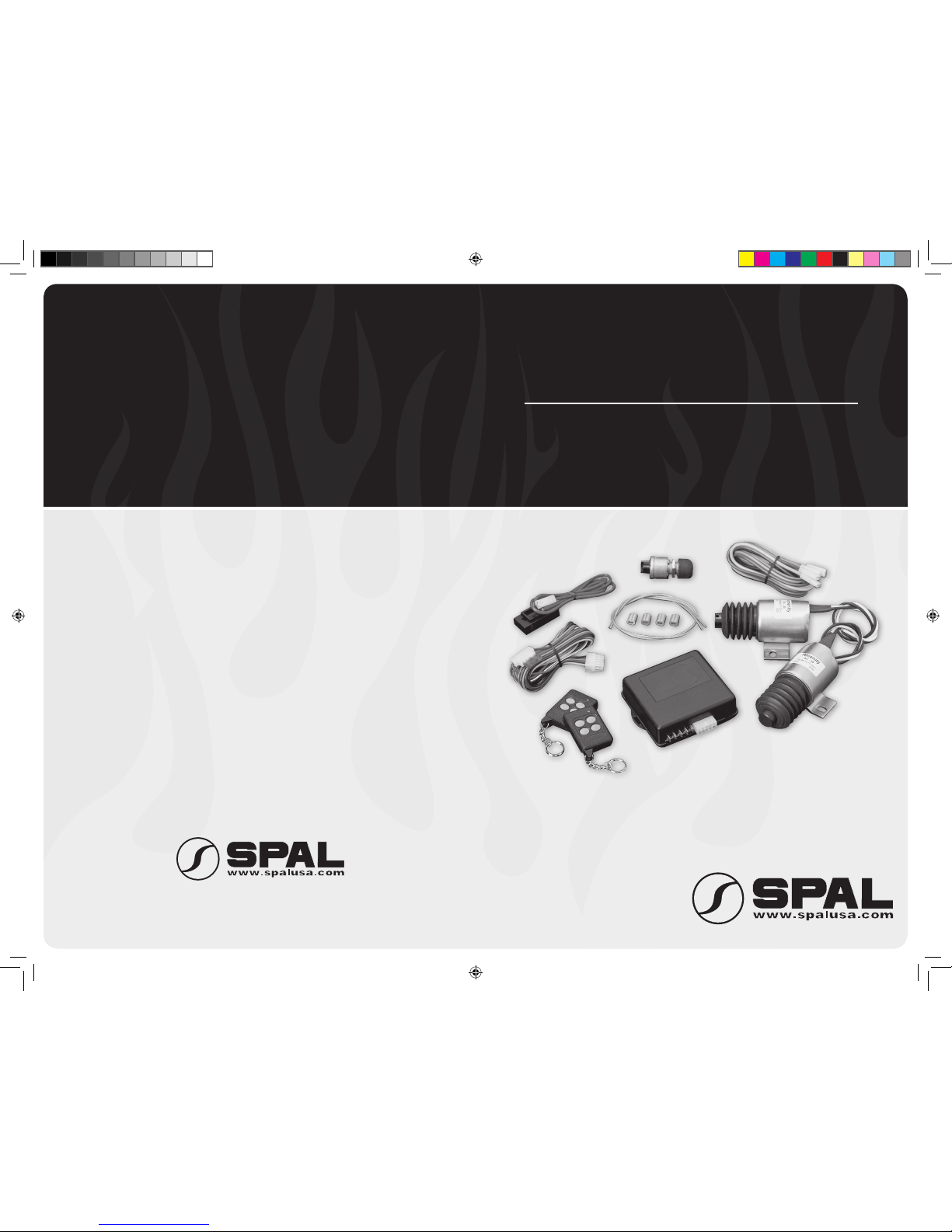
Our most popular kit comes complete with (1) seven-channel receiver, (2)
remote transmitters and (2) solenoids with 40 pounds of pull each. This kit
also includes all necessary hardware for installation. The SHAVED-40 kit of-
fers enough pull to open virtually any door on the market today.
®
Li mi t e d Wa r r a n t y St a t e m e n t
SPAL USA Wa r r a n t y Sta t e m e n t
SPAL USA warrants this product to be free from defects in
material and workmanship for a period of one (1) year from
the date of sale to the original purchaser, and not more than
two (2) years from the date of manufacture. SPAL USA will
repair this product free of charge if, in the judgment of SPAL
USA, it has been proven defective within the warranty period. The product should be returned, at the customer expense, to the location of original purchase. This warranty
does not cover any expenses incurred in the removal and/
or reinstallation of the product.This warranty does not apply
to any product damaged by improper installation, accidental
misuse, abuse, improper line voltage, fire, flood, lightning, or
other acts of God, or a product altered or repaired by anyone
other than SPAL USA.This warranty is in lieu of other warranties, expressed or implied, including any implied warranty of
merchantability. No person is authorized to assume for SPAL
USA any other liability concerning the sale of this product.
IMPORTANT-KEEP YOUR INVOICE WITH THIS WARRANTY STATEMENT!
1731 SE Oralabor Road • Ankeny, IA 50021
Sales: 800-345-0327 • Fax: 800-654-7725
Tech Support Line: 800-454-7725 (M-F / 8am - 5pm CST)
tech@spalusa.com • www.spalusa.com
JayCorp Technologies
order at www.jaycorptech.com
866-529-2677
>>> PLEASE NOTE! <<<
Power and ground to the 10-PIN connector
must be hooked up to the control module
for the unit to operate correctly!
INSTALLATION MANUAL &
OPERATION INSTRUCTIONS
SHAVED-40
INSTALLATION MANUAL &
OPERATION INSTRUCTIONS
SHAVED-40
www.spalusa.comwww.spalusa.com
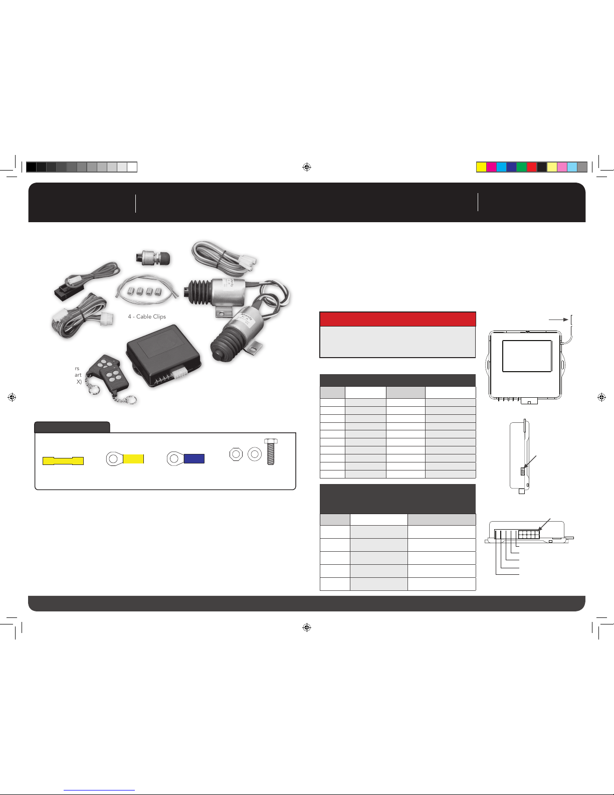
1 2
High Current
Switch
12ga Wiring
2 - 40lb
Solenoids
2 - Nylon Cables
4 - Cable Clips
Control
Module
2 - Transmitters
(Replacment Part
#MULTI-RCU7TX)
10-Pin Molex-Styk
Connector (Includes
5Amp Fuse)
12ga Wiring (Includes
35Amp Fuse) For
Middle Male Spade
Terminal
CHANNEL 4
CHANNEL 1 INPUT
CHANNEL 6
IGNITION
BROWN
WHITE/BLACK
GREY
YELLOW
CHANNEL 3
CHANNEL 5
CHANNEL 7
CHANNEL 2 INPUT
GROUND
CIRCUIT
+12V
COLOR
ORANGE
BLUE
PURPLE
GREEN
BLACK
RED
CHANNEL 4
CHANNEL 1 INPUT
CHANNEL 6
IGNITION
BROWN
WHITE/BLACK
GREY
YELLOW
CHANNEL 3
CHANNEL 5
CHANNEL 7
CHANNEL 2 INPUT
GROUND
CIRCUIT
+12V
COLOR
ORANGE
BLUE
PURPLE
GREEN
BLACK
RED
CHANNEL 7
CHANNEL 2 INPUT
GROUND
CIRCUIT
COLOR
PURPLE
GREEN
BLACK
CHANNEL 4
CHANNEL 1 INPUT
CHANNEL 6
IGNITION
BROWN
WHITE/BLACK
GREY
YELLOW
CHANNEL 3
CHANNEL 5
CHANNEL 7
CHANNEL 2 INPUT
GROUND
CIRCUIT
+12V
COLOR
ORANGE
BLUE
PURPLE
GREEN
BLACK
RED
(2) Yellow 5/16”
Ring Terminals
(2) Yellow Butt
Connectors
(2) Blue Butt
Connectors
(4) 1/4” x 20 x 1 Mounting
Bolts/ Nuts/Washers
Accessories
Fu n c t i o n a l i t y :
The SHAVED-40 is designed to operate up to 7 functions. Channels 1 and 2
are controlled by 2 on-board relays (see page #2 for output locations). Chan-
nels 3 through 7 are controlled by negative output wires (see page #2
for output locations) supplied to external relays (not provided).
Fe a t u r e s :
op e r a t i o n :
1) Control module can hold up to (4) key fobs (transmitters) with different signals.
2) Control module incorporates a lock pulse timer that provides a .4 second pulse from the control
module to the device(s). If the buttons on the key fob (transmitter) are held down for an extended
period, the lock pulse timer will prevent the device(s) from being damaged.
3) Control module incoporates a time-out feature that eliminates damage to the device(s) by shutting
down the system for 30 seconds if the buttons on the key fob (transmitter) are activated more then
8 times in a 30 second period. After the 30 second time-out period, the system will function as
normal.
4) Key fob (transmitter) has a range of 150’ maximum.
10-Pin Ma t i n g Co n n e C t o r 9357-10
CAVITY CIRCUIT WIRE COLOR FUNCTION
1 Ground Black To Ground
2 Not Used Green ---
3 Channel 7 Purple Negative Output
4 Channel 5 Blue Negative Output
5 Channel 3 Orange Negative Output
6 +12V Red To Power
7 Ignition Yellow To Ignition Power
8 Not Used Grey ---
9 Channel 6 White/Black Negative Output
10 Channel 4 Brown Negative Output
SP a d e te r M i n a l S (Po S t i o n 1 iS Cl o S e S t to
10-Pin Co n n e C t o r ) Ma t i n g Co n n e C t o r
.250” Fe M a l e te r M i n a l
POSITION CIRCUIT WIRE COLOR
1 Not Used Violet
2 Not Used Orange
3 12V Red
4 Channel 1 Brown
5 Channel 2 Yellow
Antenna 15” Long
(Do Not Ground Or Cut)
LED (Red)
10-Pin Connector
12345
678910
1
2
3
4
5
Spade Terminals
JayCorp Technologies
order at www.jaycorptech.com
866-529-2677
 Loading...