

Spa Electrics ATOM Installation & Owner's Manual
CONCRETE POOLS
ULTRA COMPACT NICHE LIGHT
INSTALLATION &
OWNER’S MANUAL

CONTENTS
READ THIS FIRST 5
TOOLS REQUIRED
INCLUDED PARTS
INSTALLATION INSTRUCTIONS
LIGHT ASSEMBLY
LIGHT REMOVAL
TROUBLESHOOTING
6
6PRODUCT SUPPORT & INFORMATION
7
8FINISHED INSTALLATION
9
18
19
20KEY DIMENSIONS
21
22ELECTRICAL GROUNDING & FCC COMPLIANCE STATEMENT
NOTICE
FRESH WATER USE ONLY
HORIZONTAL MOUNT ONLY
NOT INTENDED FOR OPERATION OUT OF WATER
FOR SUPPLY CONNECTION, USE ONLY AN ISOLATING LOW VOLTAGE POWER
SUPPLY WITH UNGROUNDED OUTPUT, EVALUATED FOR SWIMMING POOL USE
3


The ATOM light must only be used with a UL listed 12V AC Class 2 power supply or a power
source intended for swimming pool use (not included).
Minimum power source wattage requirement - 15 Watts per light.
•
DO NOT use electronic or switch-mode power supplies with ATOM lights. These power supplies will
damage the light and void your product warranty.
• Pool chemicals & PH levels: Due to the corrosive nature of unbalanced pool chemicals, Spa
Electrics strongly recommend that your pool water is balanced prior to installing your pool lights or
any plastic or stainless steel components, and tested weekly to maintain these levels. pH levels
should be maintained between 7.2 – 7.6 at all times to ensure the longevity of these components.
> Failure to do so can result in chemical damage to the light housing and pool fittings,
including stainless steel components.
> Please note: Lights or components found to have excessive chemical damage will not
be covered under our manufacturer’s warranty policy.
• This light contains no user-serviceable parts; opening the light will void the product warranty.
IMPORTANT NOTE
READ THIS FIRST
Congratulations on your purchase of the ATOM underwater lighting system. All ATOM lights are
manufactured by Spa Electrics in Australia from only the highest quality materials. For more
information about Spa Electrics & our products, please visit www.spaelectrics.com.au
BEFORE YOU START:
• ATOM cables can be shortened to suit individual installation requirements. Spa Electrics
recommends all cabling is protected by conduit and that a junction box (or similar) is
incorporated into pool cabling design to avoid siphoning.
• Ensure that the lighting system is installed by a qualified person (e.g. registered pool builder
and/or licensed electrician), in accordance with the most current edition and/or amendment of
current NEC wiring code.
• For safe and proper installation, ensure that only those parts supplied with the system are used.
• Maximum installation depth for the ATOM light is 1.2ft (14”) below water line (to top of light).
• The ATOM light must be correctly installed in or on the wall of the pool with the top of the lens no
less than 4” below the nominal water level.
• All lights should be mounted in a location that is easily accessible without the need for entering
or lowering the pool water.
• 20” cable has been supplied pre-assembled within niche assembly, and must remain stored
within the Niche to ensure the light can be accessed above the waterline. [Maximum cable within
niche = 24” (18AWG & 16AWG). See Page 16 for more information].
CLEANING
• Only use warm water and a soft brush or cloth to clean ATOM lights. DO NOT use detergents or
spirits as this can damage the light and void your warranty.
USE
• DO NOT operate light unless completely submerged in water.
• Operating the light for at least 15 minutes every week is advised (all year round).
• ATO M lights are suited for both domestic and commercial installations and can be operated
continuously (24/7) if required.
• Temperature range for installation, operation and servicing: +32
o
F ~ +104oF (0oC ~ +40oC)
5
IMPORTANT NOTES
WINTERIZATION
TOOLS REQUIRED
• No. 2 Phillips screwdriver
• Flat-blade screw driver (for light-head removal)
• The use of power tools during installation is not recommended as these
devices can cause faults and damage to light components.
• All installation steps should be carried out with manual tools only.
• The enclosed images are for illustrative purposes only. Appearances of parts
and assemblies may vary from the enclosed illustrations.
• Please contact your reseller if you have any questions regarding the correct
installation of this product.
• Lights must be removed from pool wall and cable disconnected via plug
connection & stored in a safe place.
• Terminal Cover must be fitted to Plug Top prior to reinstalling into niche for
winter.
• Unless niche/conduit connection is adequately sealed (i.e. via included cable
gland components), pool water level must be drained down 12” below the
lowest light(s) position in pool wall.
• All conduits should be checked for accumulated water and drained if required.
• Consult your local pool professional for complete pool winterization process.
PRODUCT SUPPORT & INFORMATION
Phone: +61 3 9793 2299 (business hours)
Email: info@spaelectrics.com.au (SALES enquiries)
Email: tech@spaelectrics.com.au (TECHNICAL support enquiries)
Web: www.spaelectrics.com.au
6
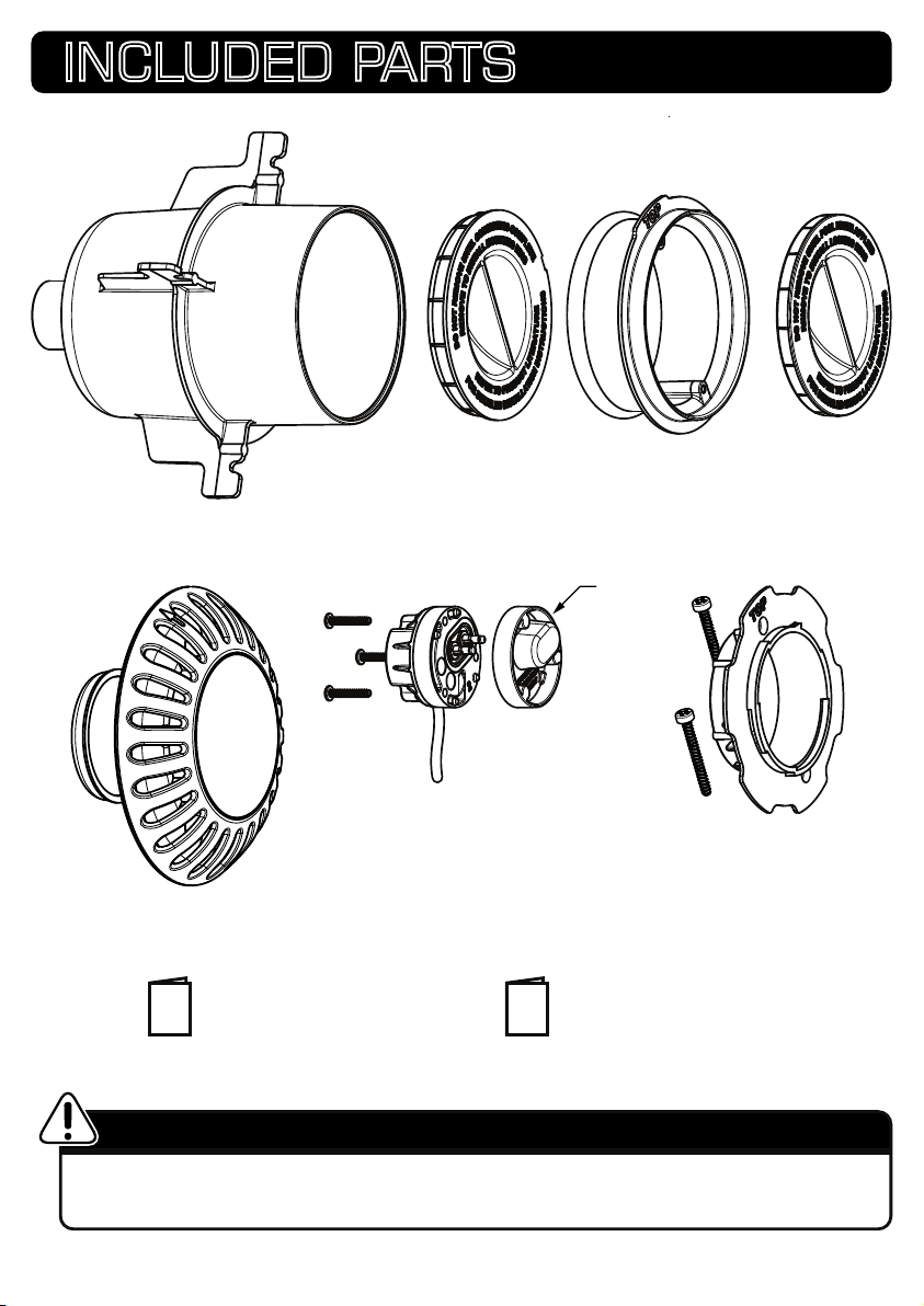
REQUIRED PART (NOT INCLUDED)
INCLUDED PARTS
LIGHT
NICHE
(REAR EXIT w/
GLAND)
PROTECTIVE
CAP
MOUNTING RING
+1 SPARE*
PROTECTIVE
PLUG + CABLE
* 1 SPARE TERMINAL COVER PROVIDED
FOR WINTERIZATION (SEE PAGE 4)
LOCKING RING
1x WARRANTY CARD 1x INSTALLATION MANUAL
CAP
UL LISTED 12V AC CLASS 2 POWER SUPPLY OR POWER SOURCE INTENDED FOR SWIMMING POOL USE.
Minimum power source wattage requirement - 15 Watts per light
Spa Electrics recommends “INTERMATIC PX” safety transformers for use with ATOM lights
7
ELECTRICAL GROUNDING
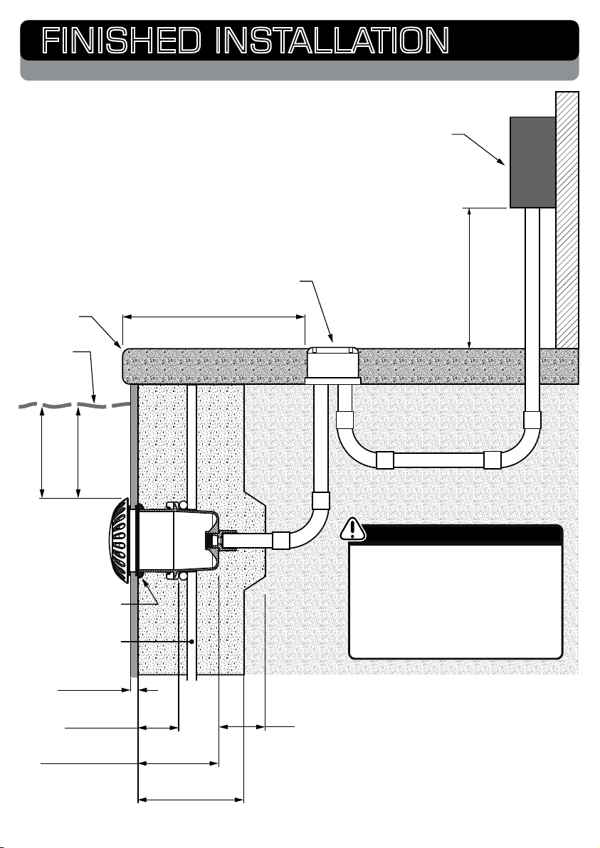
FINISHED INSTALLATION
STANDARD WALL MOUNTING
Depending on your installation requirements,
conduits may run to a common junction box or
return directly to the power supply. In either case,
it is imperative that the conduit extends above the
water level of the pool at some point in order to
prevent siphoning.
NOTE: Conduit should contain a draw-wire to
allow easy installation of power cable
JUNCTION BOX
COPING
WATER
LINE
40”
(MAX)
4”
(MIN)
48” (1.22m) MINIMUM
POWER SUPPLY
(TRANSFORMER)
2ft (MIN) CONDUIT
ELEVATION ABOVE
WATER / GROUND
SEALING
COMPOUND
RE-BAR
POOL FINISH
(SEE PAGE 11)
2.5“ (MAX)
1.75“ (MIN)
5.5” (STANDARD)
4.75” (MINIMUM)
NICHE DEPTH
8
CONCRETE
THICKNESS
DUE TO ITS PLASTIC HOUSING AND
PLASTIC NICHE DESIGN, THE ATOM
LUMINAIRE DOES NOT REQUIRE
GROUNDING / BONDING WHEN
OPERATED WITHIN A CLASS 2 CIRCUIT
SUPPLY.
SEE PAGE 23 FOR MORE INFORMATION
2”
MINIMUM
CONCRETE
COVERAGE
 Loading...