

SpacePak WCSP-D series, WCSP-3642D, WCSP-4860D, WCSP-2430D Installation, Operation & Maintenance Manual
Page 1
SECTION 1: INTRODUCTION
SpacePak System Design.......................................
Code Compliance.....................................................
Air Distribution Requirements...................................
Air Distribution Components.....................................
Warranty Information................................................
Shipment of Unit.......................................................
SECTION 2: SYSTEM INSTALLATION
Step 1: Locating The Unit.........................................
Step 2: Cutting Return Air Opening..........................
Step 3: Attaching Supply Air Plenum Adaptor...............
Step 4: Setting The Unit............................................
2
2
2
3
5
5
6
8
9
11
Step 5: Installing The Condensate Trap & Line.....
Step 6: Wiring The Unit..........................................
Step 7: Installing Air Distribution Components.......
SECTION 3: START UP & OPERATION
Sequence Of Operation.........................................
Prior To Start-Up....................................................
System Start-Up & Adjustments............................
Factors Affecting the Balance of the System.........
SECTION 4: MAINTENANCE
Biannual Maintenance Checklist............................
If System Fails To Operate.....................................
Service/Troubleshooting Form...............................
Parts List................................................................
12
12, 13
14
17
18
18
19
20
20
21
22
IN UNITED STATES: 260 NORTH ELM ST. WESTFIELD, MA 01085 (413) 564-5530/FAX (413) 564-5815
IN CANADA: 7555 TRANMERE DRIVE, MISSISSAUGA, ONTARIO, L5S 1L4 (905) 672-2991/FAX (905) 672-2883
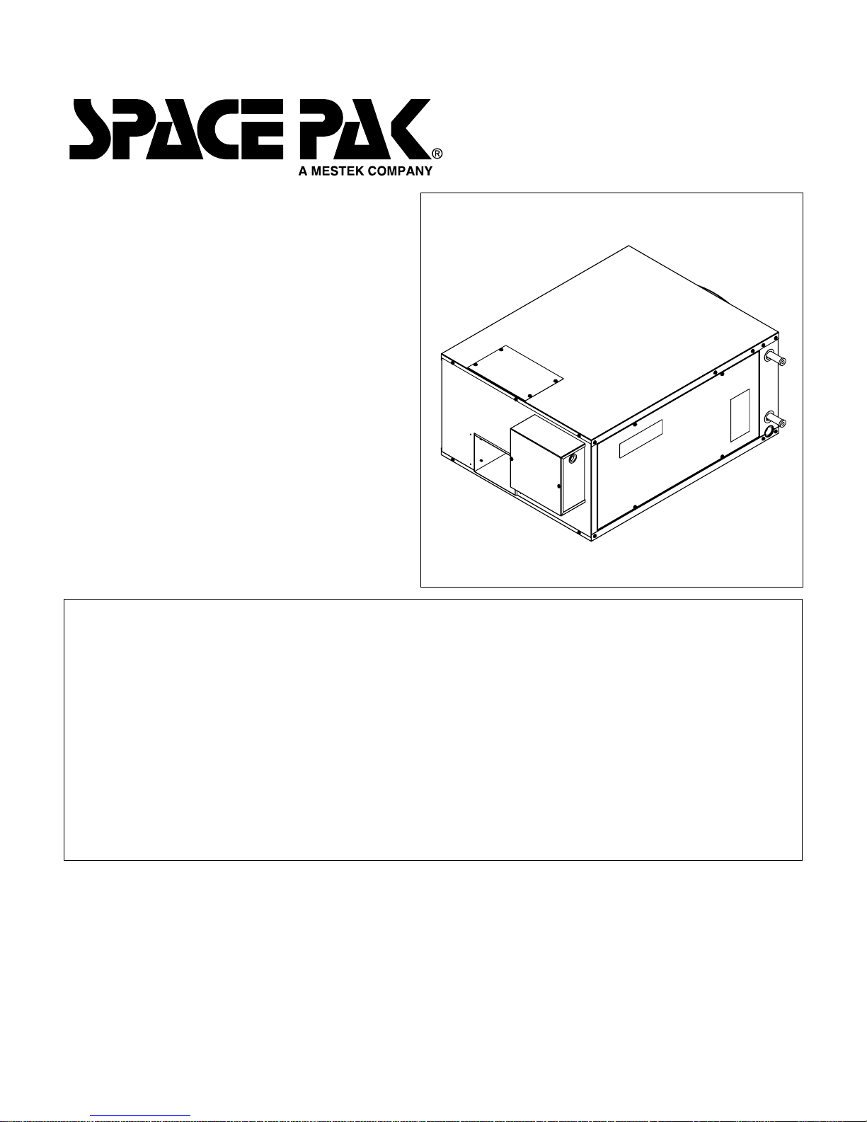
Central Hydronic Coil Series
2 to 5 Tons
Fan Coil Unit/Air Supply
Components
MODEL
WCSP-D SYSTEM
INSTALLATION,
OPERATION
& MAINTENANCE
MANUAL
WCSPD2-1205
W30-WG0135-02
SPL-0059-A
Page 2
2
SPACEPAK SYSTEM DESIGN
The SpacePak WCSP-D unit is a hydronic fan coil unit
which utilizes chilled or heated water from a chiller or
boiler to provide the conditioned air through the specially
designed prefabricated preinsulated flexible duct system.
The system and its basic components operate the same
as in any conventional air-to-air cooling system.
The SpacePak system is covered by the following U.S.
Patents: 3,507,354; 3,575,234; 3,596,936; 3,605,797;
3,685,329; 4,045,977; 4,698,982; 926,673 and Canadian
Patents: 891,292; 923,935; 923,936.
CODE COMPLIANCE
Fan coil unit installation must conform to the requirements of the local authority having jurisdiction or, in
the absence of such requirements, to the National Board
of Fire Underwriters regulations. Fan coil unit meets
ETL listing requirements.
All electrical wiring must be in accordance with
the National Electrical Code ANSI/NFPA No. 70-latest
edition and any additional state or local code requirements. If an external electrical source is utilized, the fan
coil unit, when installed, must be electrically grounded.
NOTICE: It is a requirement of the International
Mechanical Code (307.2.3 ) to install a secondary drain
or an auxiliary drain pan where damage to any building
components will occur as a result of overflow from the
equipment drain pan or stoppage in the condensate
drain piping from a cooling or an evaporator coil.
AIR DISTRIBUTION SYSTEM
COMPONENT REQUIREMENTS
Air distribution components installation must conform
to the requirements of local authority having jurisdiction
or, in the absence of such requirements, to the National
Fire Protection Association 90A or 90B.
Do not begin the installation of the system without a
system layout and material take-off. If a layout plan is
not already available and room terminator requirements
determined, then refer to the SpacePak Application
Manual, SP9, to complete this information. A description
of air distribution system components is shown in Figure
1.1.
Section 1: INTRODUCTION
The following terms are used throughout this
manual to bring attention to the presence of potential
hazards or to important information concerning the
product:
Indicates an imminently hazardous
situation which, if not avoided, will result in death,
serious injury or substantial property damage.
Indicates an imminently hazardous
situation which, if not avoided, could result in
death, serious injury or substantial property damage.
Indicates an imminently hazardous
situation which, if not avoided, may result in
minor injury or property damage.
NOTICE: Used to notify of special instructions on
installation, operation or maintenance which are
important to equipment but not related to personal
injury hazards.
Page 3
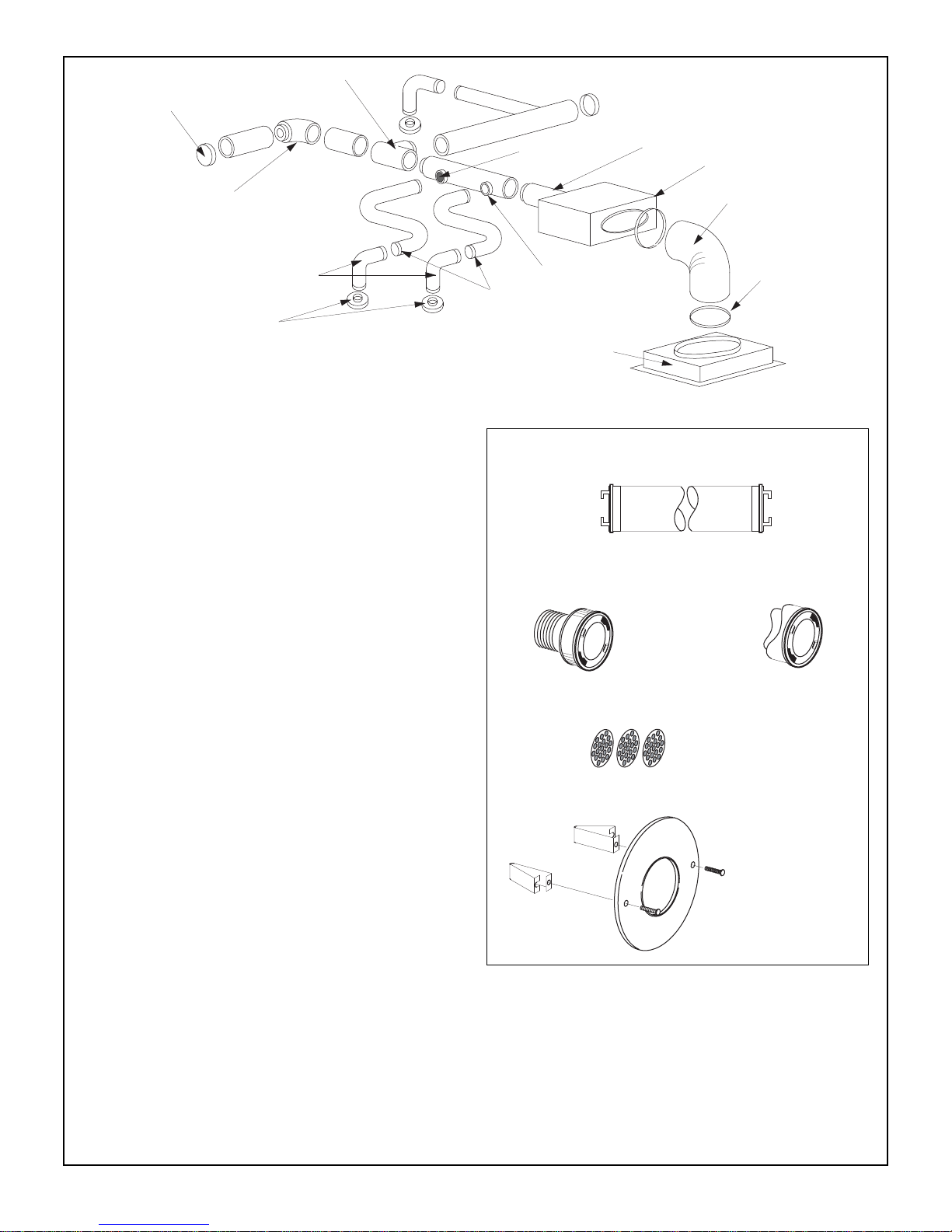
RETURN AIR DUCT
CLAMP BAND
RETURN AIR BOX
PLENUM DUCT
FAN COIL UNIT
PLENUM CAP
PLENUM TEE
PLENUM TAKEOFF
KWIK CONNECTS
SOUND ATTENUATING TUBING
TERMINATOR PLATES
ORIFICE
RIGID 90° ELBOW
3
RETURN AIR BOX (SPC-1D, AC-RBF-3, SPC-3D):
Each includes filter grill with metal frame, permanent
filter, and 2 clamp bands. SPD-1D is for
WCSP-2430D. AC-RBF-3 is for WCSP-3642D and
SPC-3D is for WCSP-4860D.
RETURN AIR DUCT (SPC-4,5, & 6): Flexible,
10 feet long with round shape. SPC-4 (15" dia.) for
WCSP-2430D. SPC-5 (19" dia.) for WCSP-3642D
and SPC-6 (24" dia.) is for WCSP-4860D.
PLENUM DUCT & COMPONENTS: May be round or
square, fiberboard or sheet metal duct types as specified by the installing contractor. Above layout is shown
as an illustrative reference only.
SUPPLY TUBING (SPC-25-100): Flexible, insulated,
2" I.D. and 3
1
⁄4" O.D. Each section is 100 feet long.
R8 SUPPLY TUBING (AC-ST8-50): Flexible, R8 insulated,
2" I.D. and 6
1
⁄4" O.D. Each section is 50 feet long.
INSTALLATION KITS: Each contains a specified
amount of sound attenuating tubes, kwik-connects,
plenum take-offs, terminator plates, winter supply air
shut-offs and balancing orifices to complete installation
of room outlets.
ADDITIONAL COMPONENTS (not shown)
WINTER SUPPLY SHUT OFF (SPC-42-10): To keep
moisture from collecting in ductwork during winter
months.
KWIK CONNECT WALL ELBOW (AC-KCWE): to allow
for wall terminations in 2" X 4" stud spaces.
FIGURE 1.1: AIR DISTRIBUTION SYSTEM COMPONENTS
PLIERS (SPC-72): To assure full setting of all clips
(fasteners) in plenum take-off.
SECONDARY DRAIN PAN: specifically sized for
SpacePak horizontal fan coil units. Constructed of
durable polyethylene. Fan coil unit sets directly on top
and can be installed with threaded rod.
INSTALLATION KIT COMPONENTS
Sound attenuating tube w/ kwik-connects installed
Kwik-connects,
Plenum Take-offs,
clips and gaskets.
15%, 35% and
50% balancing orifices
Terminator plates
with clips and screws
Page 4
4
Plenum Duct
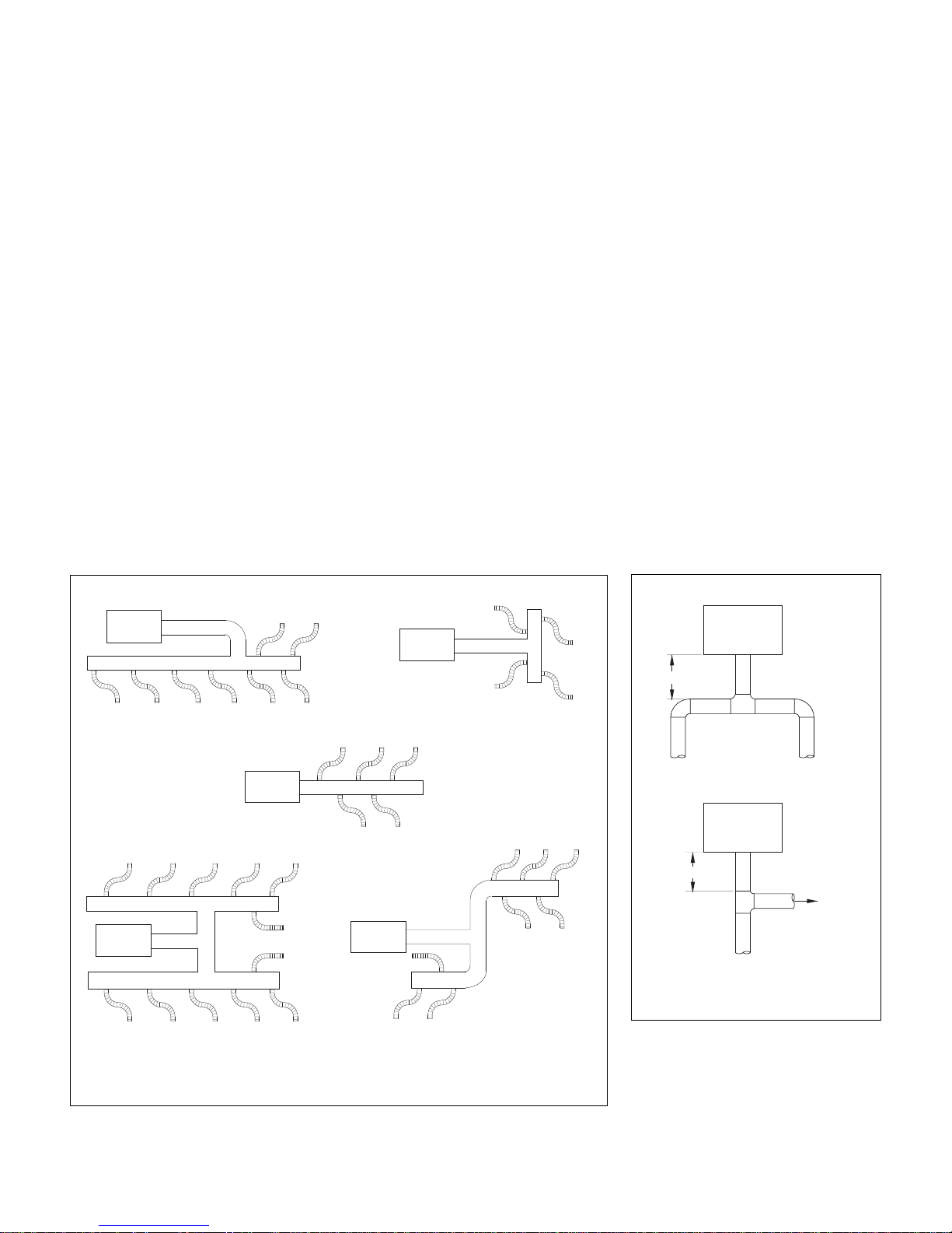
The plenum duct can be run in practically any location
accessible for the attachment of the supply tubing (see
suggested layouts in Figure 1.2). The plenum is normally
located in the attic or basement, and it is usually more
economical to run the plenum where it will appreciably
shorten the lengths of two or more supply runs.
In some two-story split level homes, it may be advantageous to go from one level to another with the plenum
duct. Whenever necessary, either between floors or along
the ceiling, the small size of the plenum makes it easy to
box in.
The fan coil unit is designed to operate with a total external static pressure of 1.5 inches of water column (minimum 1.0 - maximum 1.5). Excessive static pressure is an
indication of too few outlets and may cause the coil to
freeze and some or all outlets to be noisy.
For systems with a tee installed as on Unit No. 1 (Figure
1.3), the best results are obtained if not more than
60% of the total number of system outlets are attached to
any one branch of the tee. For systems with a tee
installed as on Unit No. 2 (Figure1.3), not more than 30%
of the total number of system outlets should be attached
to the perpendicular branch of the tee.
The larger system capacities (WCSP-4860D) are
effected more by higher system static pressure than
the smaller systems. The four and five ton systems are
ideally designed as indicated by the diagram in the lower
left corner of figure 1.2. If this layout cannot be followed,
it is important to create some pressure drop in the
plenum run using elbows and tees. Installation of the
plenum tee closer than the minimum indicated in Fig. 1.3
will reduce performance of the system. No supply runs
should be installed between unit outlet and this tee. Static
readings on system should be taken before tee.
Supply Tubing
In the case of two-story or split-level applications, supply
tubing may run from one story to another. It is small
enough to go in stud spaces, but this is often difficult
in older homes because of hidden obstructions in stud
spaces. It is more common to run the supply tubing
from the attic down through second story closets to
the first story terminators.
Supply tubing runs in the corners of the second story
rooms can be boxed in and are hardly noticeable since
overall diameter is only 31⁄4".
FIGURE 1.2: PLENUM/TUBING LAYOUT EXAMPLES
(FOR GUIDANCE ONLY)
FIGURE 1.3:
WCSP-4860D INSTALLATION
FAN COIL
UNIT
FOR
WCSP- 4860
ONLY
PLENUM
PLENUM
FAN COIL
UNIT
PLENUM
FAN COIL
UNIT
FAN COIL
UNIT
PLENUM
PLENUM
UNIT NO. 1
FAN COIL UNIT
NO MORE THAN
MINIMUM 18"
MINIMUM 18"
60% OF CAPACITY
ON ONE SIDE
UNIT NO. 2
FAN COIL UNIT
30% MAX. OF CAPACITY
Page 5
5
Room Terminators
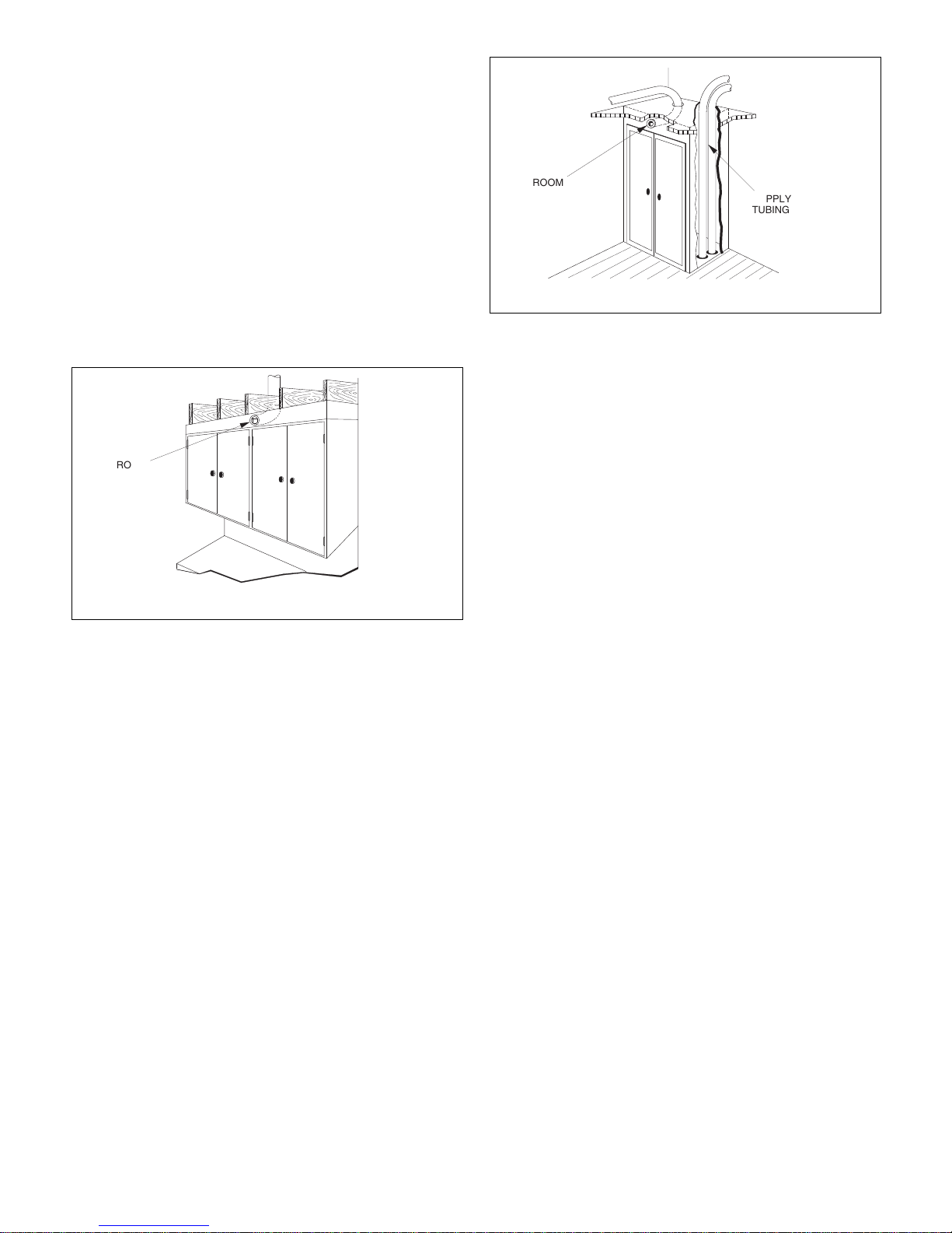
Terminators should be located only in the ceiling or floor
for vertical discharge. Horizontal discharge is acceptable,
but is sometimes more difficult to install. Two excellent
spots for horizontal discharge are in the soffit area
above kitchen cabinets (see Figure 1.4) and in the top
portion of closets (see Figure 1.5).
Terminators should always be out of normal traffic
patterns to prevent discharge air from blowing directly
on occupants. And they should not be located directly
above shelves or large pieces of furniture. Outside wall
or corner locations are recommended if the room has
more than one outside wall. Locating terminators away
from interior doors prevents short cycling of air to the
return air box.
WARRANTY INFORMATION
Refer to the Limited Warranty published on the back
page of this manual.
SHIPMENT OF UNIT
Each fan coil unit is shipped in a single carton. Packed with
the unit, there are vibration isolation pads, a condensate
trap assembly, a length of 6" wide foil faced fiberglass insulation and a factory installed primary float switch.
FIGURE 1.4: TERMINATOR IN SOFFIT AREA
FIGURE 1.5: TERMINATOR IN CLOSET TOP AREA
SECTION 2: SYSTEM INSTALLATION
NOTICE: Before proceeding with the installation, we
recommend reading through this section of the
manual for an overall understanding of the air
conditioning fan coil unit and air distribution system
component installation procedures.
STEP 1: LOCATING THE UNIT
The fan coil unit may be installed in an unconditioned
space (as long as it is protected from the weather) such
as an attic, garage or crawlspace...or a conditioned
space such as a basement, closet or utility room (see
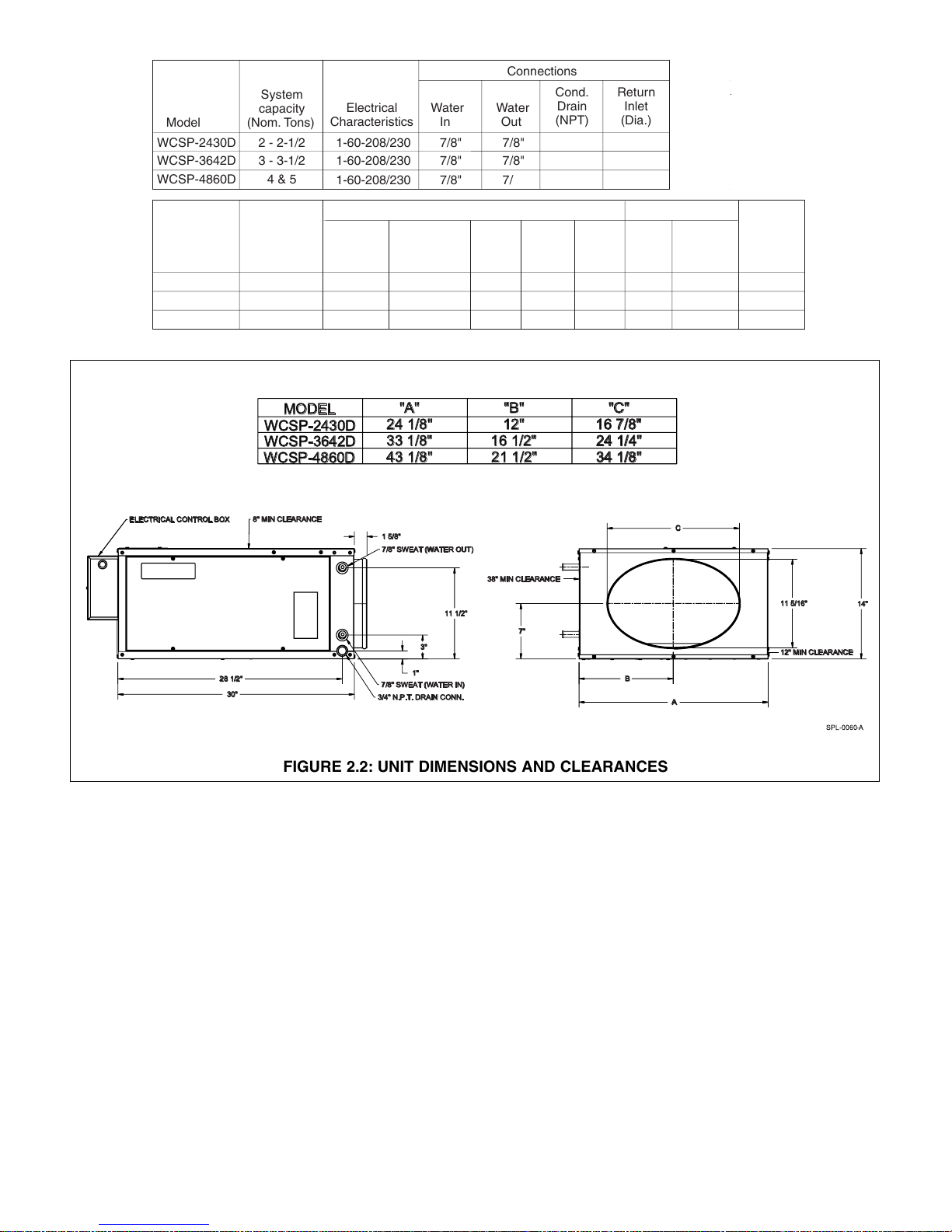
dimensions in Figure 2.2).
The fan coil unit is shipped set-up for horizontal supply
air discharge. This can be easily field converted to vertical discharge, as detailed on pg. 9 and Figures 2.9A and
2.9B pg. 10.
When selecting a location, consider the locations (as
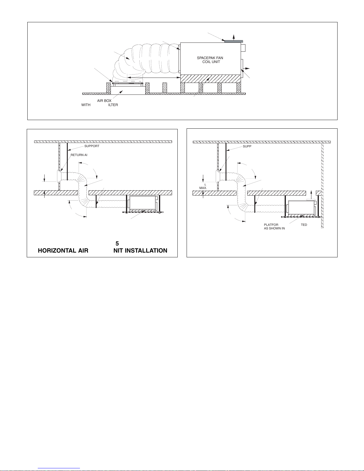
shown in Figures 2.4, 2.5 and 2.6) of the return air box;
routing of the plenum duct, supply tubing, refrigerant
lines, condensate drain line; and all recommended clearances (see Figures 2.2).
NOTICE: It is a requirement of the International
Mechanical Code (307.2.3) to install a secondary
drain or an auxiliary drain pan where damage to any
building components will occur as a result of overflow from the equipment drain pan or stoppage in the
condensate drain piping from a cooling or an evaporator coil.
Follow local code requirements.
ROOM
TERMINATOR
ROOM
TERMINATOR
SUPPLY
TUBING
Page 6
6
28 1/2"
30"
1"
3"
11 1/2"
1 5/8"
14"
A
C
11 5/16"
"C"
16 7/8"
24 1/4"
34 1/8"
"B"
12"
16 1/2"
21 1/2"
MODEL
WCSP-2430D
WCSP-3642D
WCSP-4860D
"A"
24 1/8"
33 1/8"
43 1/8"
7/8" SWEAT (WATER OUT)
7/8" SWEAT (WATER IN)
3/4" N.P.T. DRAIN CONN.
ELECTRICAL CONTROL BOX
B
7"
8" MIN CLEARANCE
38" MIN CLEARANCE
12" MIN CLEARANCE
SPL-0060-A
FIGURE 2.2: UNIT DIMENSIONS AND CLEARANCES
Model
Bottom
To p
FIGURE 2.1: MODEL WCSP-D SPECIFICATIONS
WCSP-2430D
WCSP-3642D
WCSP-4860D
System
capacity
(Nom. Tons)
2 - 2-1/2
3 - 3-1/2
4 & 5
Electrical
Characteristics
1-60-208/230
1-60-208/230
1-60-208/230
Water
In
7/8"
7/8"
7/8"
Connections
Water
Out
7/8"
7/8"
7/8"
Cond.
Drain
(NPT)
3/4"
3/4"
3/4"
Return
Inlet
(Dia.)
15"
19"
24"
Model
WCSP-2430D
WCSP-3642D
WCSP-4860D
System
capacity
(Nom. Tons)
2 - 2-1/2
3 - 3-1/2
4 & 5
Blower
Std.
CFM @
1.5" W.C.
550 1/3
850
1150
Wheel Dia.
and
Width
9" x 5"
9" x 5"
9" x 6-3/8"
Motor
HP
1/2
1
Motor
Type
PSC
PSC
PSC
F. L .
Amps
1.8
2.8
3.6
No. of
Rows
Deep
6
6
6
Coil
per Ton
(GPM)
2.4 112
2.4
2.4
Ship.Flow Rate
Wt.
(lbs)
134
171
Page 7
7
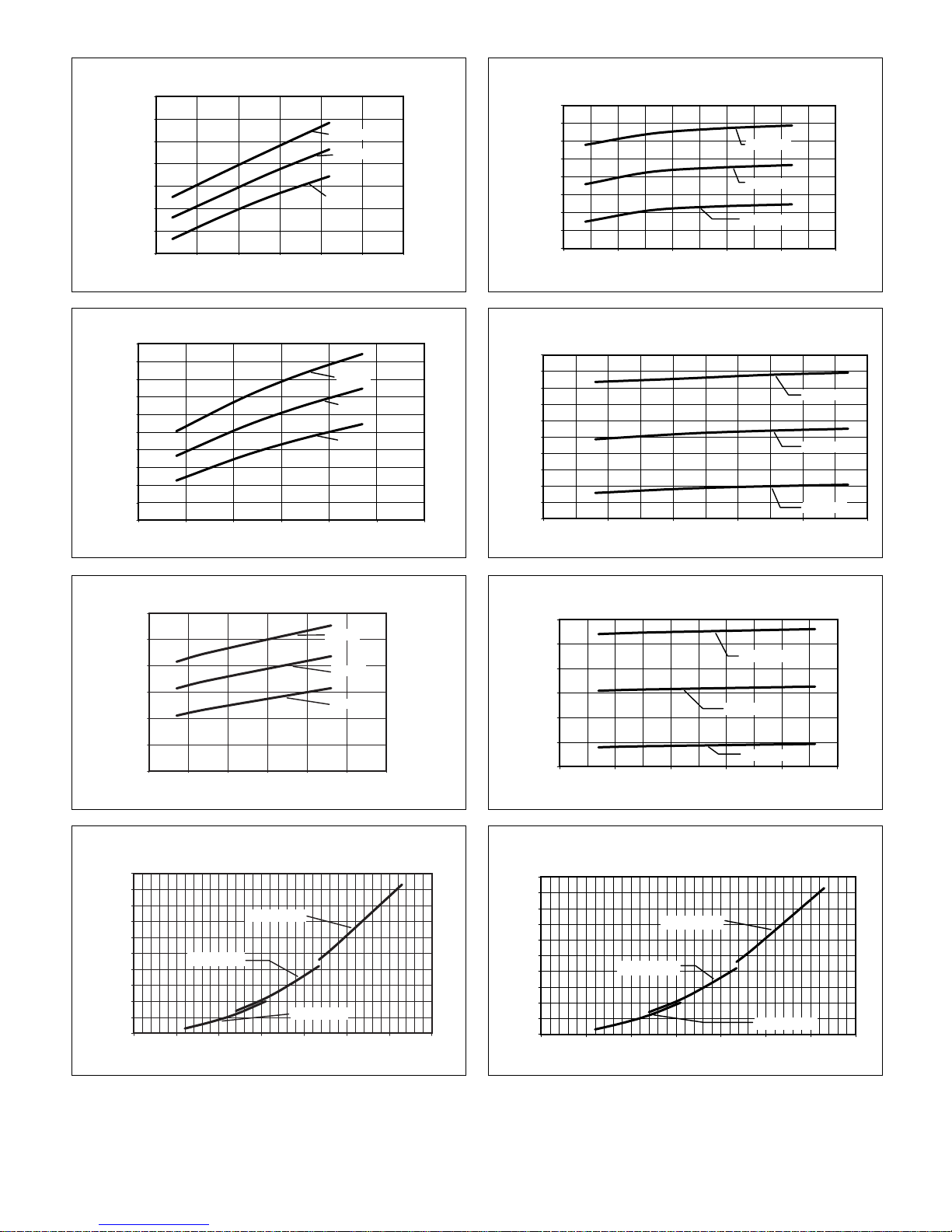
12.0
14.0
16.0
18.0
20.0
22.0
24.0
26.0
2.0 3.0 4.0 5.0 6.0 7.0 8.0
Water Flow Rate - GPM
Cooling Capacity MBH
48 EWT
45 EWT
42 EWT
20.0
25.0
30.0
35.0
40.0
45.0
50.0
55.0
60.0
2.0 3.0 4.0 5.0 6.0 7.0
Water Flow Rate, GPM
Heating Capacity, MBH
160 EWT
140 EWT
120 EWT
WCSP-2430D @ 550 cfm Cooling Capacity WCSP-2430D @ 550 cfm Heating Capacity
20.0
22.0
24.0
26.0
28.0
30.0
32.0
34.0
36.0
38.0
40.0
4.0 5.0 6.0 7.0 8.0 9.0 10.0
Water Flow Rate - GPM
Cooling Capacity MBH
45 EWT
48 EWT
42 EWT
WCSP-3642D @ 850 cfm Cooling Capacity
40.0
45.0
50.0
55.0
60.0
65.0
70.0
75.0
80.0
85.0
90.0
4.0 5.0 6.0 7.0 8.0 9.0
Water Flow Rate, GPM
Heating Capacity, MBH
160 EWT
140 EWT
120 EWT
WCSP-3642D @ 850 cfm Heating Capacity
30.0
35.0
40.0
45.0
50.0
55.0
60.0
8.0
9.0 10.0 11.0 12.0 13.0 14.0
Water Flow Rate - GPM
Cooling Capacity MBH
42 EWT
48 EWT
45 EWT
60.0
70.0
80.0
90.0
100.0
110.0
120.0
8.0 9.0 10.0 11.0 12.0 13.0
Water Flow Rate, GPM
Heating Capacity, MBH
160 EWT
140 EWT
120 EWT
WCSP-4860D @ 1150 cfm Cooling Capacity WCSP-4860D @ 1150 cfm Heating Capacity
0.0
1.0
2.0
3.0
4.0
5.0
6.0
7.0
8.0
9.0
10.0
0.0 2.0 4.0 6.0 8.0 10.0 12.0 14.0
Water Flow Rate, GPM
Water Pressure Drop, PSI
WCSP-4860D
WCSP-3642D
WCSP-2430D
Hydronic Coil Pressure Drop Characteristics
0.0
1.0
2.0
3.0
4.0
5.0
6.0
7.0
8.0
9.0
10.0
0.0 2.0 4.0 6.0 8.0 10.0 12.0 14.0
Water Flow Rate, GPM
Water Pressure Drop, PSI
WCSP-4860D
WCSP-3642D
WCSP-2430D
Hydronic Coil Pressure Drop Characteristics
Page 8
8
STEP 2: CUTTING RETURN AIR OPENING
Select exact location for return air box. Avoid installing
box in dining room, living room, kitchen, etc., unless
return air duct can be installed with at least two 90°
bends (accomplished by splicing two return air ducts
together.)
For attic installations to raise fan coil unit up through
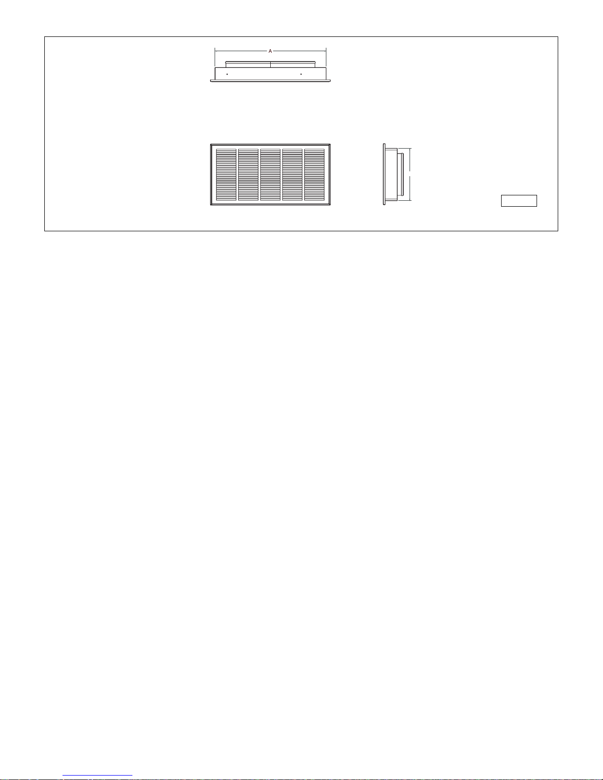
opening, cut return air opening 14
1
/2" wide by 27" long
for the WCSP-2430D, 141/2" wide by 311/2" long for the
WCSP-3642D* and 141/2" wide by 361/2" long for the
WCSP-4860D. These openings will accomodate the
return air box with sufficient frame lip to cover the
opening (see Figure 2.7).
NOTICE: The electrical box must be removed from
the WCSP-3642 unit to fit through hole cut out.
Refer to the "Installation Tip" supplied with the return
air box.
If ceiling joists are on 16" centers, the 141/2" width of the
return air box should fit between successive joists.
Where joists run in the opposite direction, or to properly
center the return, it may be necessary to cut joists and
install headers.
For all wall return applications, cut the return air opening
to accomodate the return air box (measure box itself).
Remember, location of opening must allow for a 90° bend
in the return air duct.
Check the opening for proper fit of the return air box. Do
not install the return air box until the installation of the
entire SpacePak system is completed, if you want to fit
materials up through this hole.
14 Ft. MAXIMUM FLEXIBLE
RETURN DUCT
FAN COIL UNIT
SUPPORT
RETURN AIR BOX
90°
90°
2 Ft.
MAX.
PLATFORM (FIELD ERECTED
AS SHOWN IN STEP 4)
SUPPORT
FIGURE 2.5
HORIZONTAL AIR FLOW UNIT INSTALLATION
14 Ft. MAXIMUM FLEXIBLE
RETURN DUCT
FAN COIL UNIT
SUPPORT
SUPPORT
RETURN AIR BOX
90°
90°
2 Ft.
MAX.
PLATFORM (FIELD ERECTED
AS SHOWN IN STEP 4)
SUPPLY
AIR
FIGURE 2.6
VERTICAL AIR FLOW UNIT INSTALLATION
FLEXIBLE RETURN
FIGURE 2.4: TYPICAL UNIT INSTALLATION
DUCT (90˚ BEND)
CLAMP BAND
CLAMP BAND
48" MIN.
SUPPLY AIR OUTLET
(ALTERNATE LOCATION)
SPACEPAK FAN
COIL UNIT
SUPPLY AIR OUTLET
RETURN AIR BOX
WITH GRILL & FILTER
PLATFORM (FIELD ERECTED
AS SHOWN IN STEP 4)
Page 9
9
7. Attach the two flanges supplied, one to each side of
the blower housing outlet. Align the holes in the
flange with the holes in the housing and attach with
screws supplied.
8. Drill out the four (4) screw holes in the top panel that
secured the removed cover plate to
1
⁄4" inch diameter.
9. Make a 2" long cut in the top panel insulation from
each corner of the opening toward the sides of the
unit to prepare for Step 11.
10. Reposition the top panel on the unit taking care to
straddle the evaporator coil with coil support brackets
and to replace all screws.
11. Fold back the top insulation flaps created in Step 9
and position the flanges on the blower housing
discharge against the top panel. Place the supply air
plenum adaptor over the opening. Align the holes in
the adaptor, gasket and top panel with the blower
housing flange holes and secure with the screws
provided. Reposition the top insulation flaps over the
blower housing flanges. The insulation must be in
place to prevent condensation forming on the top
panel.
12. Check that the blower wheel is centered in the inlet
and discharge of the blower housing. To make any
adjustments, loosen the 4 bolts securing the motor,
shift the motor as required and refasten the 4 bolts.
13. Place the coverplate removed from the top panel over
opening in the front panel and screw in place.
NOTICE: Check that all inside cabinet surfaces are
covered with insulation, add insulation if required.
An uninsulated panel will “sweat” and condensate
will form on the cabinet.
14. Replace the side access panels.
STEP 3: ATTACHING SUPPLY AIR PLENUM ADAPTOR
NOTICE: If the unit is to be located in the attic and
installed through the ceiling joists, attach the supply
plenum adaptor in the attic.
A. HORIZONTAL DISCHARGE:
Refer to duct installation instructions supplied with
fan coil unit.
B. TO CONVERT TO VERTICAL DISCHARGE:
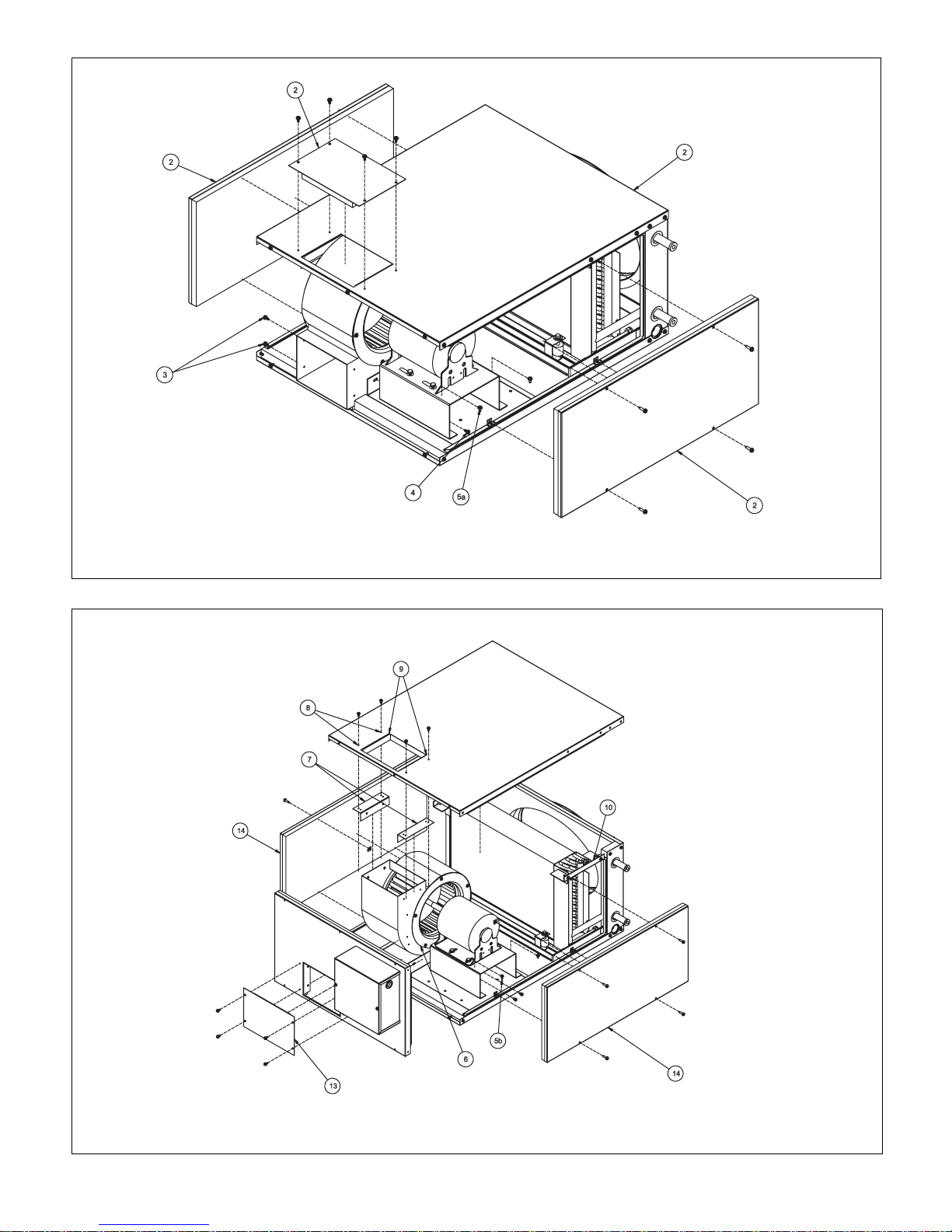
Refer to Figure 2.9A & 2.9B
Tools required:5/16" box wrench, 5/16" nut driver, drill and
1
/4" drill bit.
Refer to Figure 2.9A for Steps 2 to 5a.
1. Place unit horizontally on a flat surface.
2. Remove side access panels, the cover plate from
the top panel and top of unit.
3. Remove the two screws securing the front panel
flange to the blower housing.
4. Remove the two screws attaching the blower
housing to the motor support channel flange.
5a. Remove the six (6) screws attaching the motor
mounting base to the motor support channel.
Refer to Figure 2.9B for Steps 5b to 14.
5b. Shift the motor mounting base (and blower housing)
back towards the coil to the second set of mounting
lugs on the motor support channel. When in position,
reattach the motor mounting base to the motor support
channel with the six screws.
6. Rotate the blower housing 90° to face upwards. Align
the hole in the side blower housing with the upper slot
in the motor support channel flange and join the two
parts with one of the previously removed screws.
14-5/16"
FIGURE 2.7: RETURN AIR BOX FRAME DIMENSIONS
Measure return air box dimension
"A" to determine length of opening.
Height = 14-5/16"
DWG0045
Page 10
10
SUPPLY AIR PANEL REMOVED FOR CLAIRITY
FIGURE 2.9A
FIGURE 2.9B
SPL-0061-A
SPL-0062-A
Page 11
11
STEP 4: SETTING THE UNIT
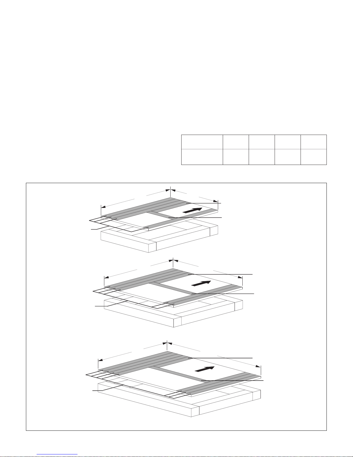
Construct a platform for the fan coil unit, as shown in
Figure 2.10. The platform can be constructed of 2x4
(minimum), 2x6, 2x8 and 2x10 lumber, as necessary to
achieve sufficient height so that proper condensate drain
line pitch of 1/4” per foot can be maintained. Figure 2.11
shows the approximate normal allowable run of condensate piping as a function of the framing lumber used for
platform construction. The platform covering should be 1⁄2"
plywood minimum.
Attach vibration isolation pads (supplied inside fan coil
unit) to platform covering as shown in Fig. 2.10.
Secure the platform to the joist or floor, depending on
location selected for the fan coil unit. Make sure platform
is level.
For locations where the fan coil unit will be suspended,
suspend platform from overhead by 1⁄4" threaded rods.
NOTICE: Leave room on sides for servicing.
For installations with a return air box and return air
duct, set fan coil unit on the platform with the elliptical
opening facing in the direction of the return air opening.
The supply air plenum adaptor should overhang the
platform. DO NOT let the adaptor support the weight of
the unit.
Do not secure the unit to the platform, as the weight of the
unit will hold it in position.
Connect refrigerant lines from outdoor condensing unit
to the fan coil unit. The refrigerant lines and unit should
be installed in accordance with the manufacturer's
instructions.
FIGURE 2.10: MOUNTING PLATFORMS SHOWN W/ VIBRATION ISOLATION STRIPS
FIGURE 2.11: CONDENSATE PIPING RUNS
30"
4 STRIPS 4" x 30" x 1" THICK
POLYURETHANE FOAM
FOR MODEL WCSP-2430D
30"
5 STRIPS 4" x 30" x 1" THICK
POLYURETHANE FOAM
FOR MODEL WCSP-3642D
LUMBER SIZE
MAXIMUM
HORIZONTAL
2 X 4
8'
2 X 6
16'
2 X 8
24'
2 X 10
25"
1 STRIP 4" x 15" x 1" THICK
AIR FLOW
34"
AIR FLOW
POLYURETHANE FOAM
1 STRIP 4" x 9" x 1" THICK
POLYURETHANE FOAM
1 STRIP 4" x 15" x 1" THICK
POLYURETHANE FOAM
1 STRIP 4" x 14" x 1" THICK
POLYURETHANE FOAM
32'
7 STRIPS 4" x 30" x 1" THICK
POLYURETHANE FOAM
FOR MODEL WCSP-4860D
30"
AIR FLOW
44"
1 STRIP 4" x 15" x 1" THICK
POLYURETHANE FOAM
1 STRIP 4" x 16" x 1" THICK
POLYURETHANE FOAM
Page 12
12
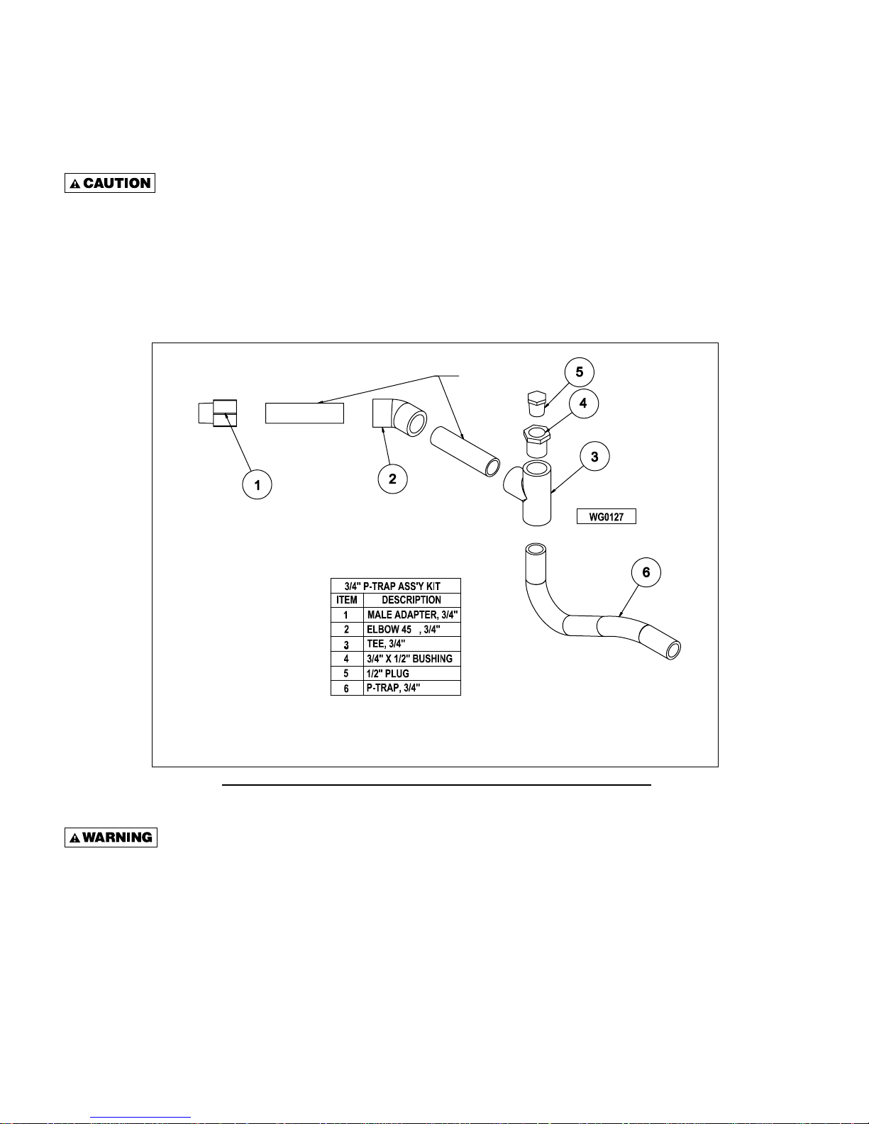
Refer to Fig. 2.2 & 2.3 for condensate drain location.
Components for the PVC condensate trap are
provided in a separate bag with fan coil unit (see Fig.
2.12) and should be cemented together with PVC pipe
cement.
Do not use substitute trap. Do not cut
off or alter trap components.
Screw male adapter (see Fig. 2.12) into unit condensate
line connection. Assemble and cement remaining
components together. Then cement assembly to male
adapter. The 45° elbow provides an offset from beneath
the unit supply and return water piping to provide access
to the clean-out plug.
STEP 5: INSTALLING THE CONDENSATE TRAP & LINE
FIGURE 2.12: CONDENSATE TRAP ASSEMBLY
STEP 6: WIRING THE UNIT
Turn off electrical power supply before
servicing. Contact with live electric components can
cause shock or death.
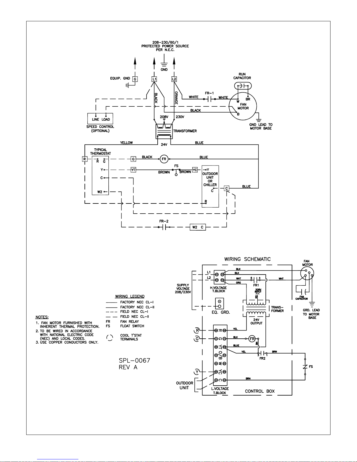
All electrical and control wiring must be installed in
accordance with the codes listed in Section 1 of this manual. Wiring diagram is provided in Figure 2.13. A
separate 208/230/60/1 power supply is recommended for
the unit. Use standard 15-amp fuse and 14-gauge wire
from power supply to unit.
Connect power supply to Terminals L1 (hot) and L2 (hot)
on the high voltage terminal block. Connect a ground wire
to the equipment ground terminal located next to
the high voltage terminal block.
The low voltage transformer in the unit has a 208 volt
tap in the primary winding (color coded RED). If unit is
to be operated with 208 volt electrical service, remove
the 230 volt ORANGE lead from the L2 terminal and
connect the 208 volt RED lead to the L2 terminal. Be sure
to insulate the end of the unused ORANGE lead.
Locate the room thermostat on a wall near the return
air box, approximately 60" from the floor. Connect the
low-voltage thermostat wiring from the room thermostat
to the low voltage control block in the unit.
Run a condensate line from the trap to a suitable
drain that’s in accordance with local codes. Make sure
the line is pitched 1⁄4" per foot.
NOTICE: Never connect condensate line to a closed
drain system.
SEE NOTE
˚
NOTE: PIPE SECTIONS ARE FIELD SUPPLIED.
Page 13
13
FIGURE 2.13: MODEL WCSP-D WIRING SCHEMATIC
Page 14

14
STEP 7: INSTALLING AIR DISTRIBUTION COMPONENTS
All plenum duct and supply tubing runs as well as
room terminator locations must be in accordance with
air distribution system requirements listed in Section 1
of this manual. Where taping of joints is required,
UL181-approved tape is recommended.
Plenum Duct Installation
All tees, elbows and branch runs must be a minimum
of 18” from the fan coil unit or any other tee, elbow
or branch run. Keep all tees and elbows to a minimum
to keep system pressure drop on larger layouts to a
minimum.
NOTICE: Refer to duct installation instructions supplied with fan coil unit or follow manufacturers
instructions supplied with other duct system types.
NOTICE: For the WCSP-4860D system, a plenum tee
must be installed 18" minimum from the fan coil unit
before continuing plenum duct run (see air distribution system requirements in Section 1 of this manual).
Page 15
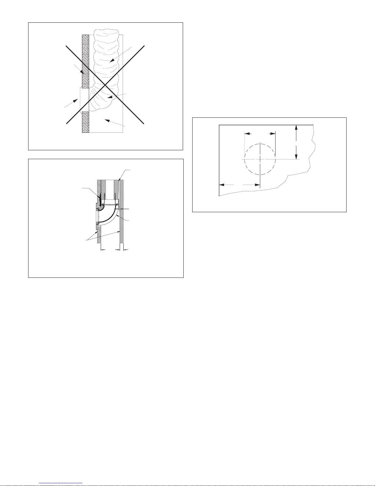
In marking location for room terminator (see Figure
2.19), the center of the terminator should be 5" from
the wall or, when installed in the corner of a room 5" from
both walls.
After marking location, drill a
1
⁄8" diameter hole for outlet
to be sure there is at least a 2" clearance all around
the 1/8" hole to receive tubing and connector. Adjust
direction of hole as needed, to gain this 2" clearance.
After all clearances have been checked, take a 4"
diameter rotary-type hole saw and cut a hole, using the
1
⁄8" diameter hole as a pilot.
Assemble the room terminator to the sound attenuating
tubing by simply fitting the two pieces together and
twisting until tight (see Figure 2.20). If the terminator is
to be used in a floor location, then field fabricate a small
screen (1
1
⁄2" square;1⁄4x 1⁄420-gauge galvanized wire
screen) and place screen over opening on the back
of the terminator prior to twisting on the kwik-connect
(on the sound attenuating tube).
NOTICE: Do not shorten sound attenuating tube
length. The result would be unacceptable noise.
Push the free end of the sound attenuating tube through
the 4" hole until the two toggle springs on the room terminator snap into place.
15
ULA
3/8
MINAL
SHEET
ROCK
SOUND
ATTENUATOR
500
625
3/16
FOR
APP
ICATIONS
ITH
THICKER
WAL
BOARD
RE
OVE MATERIAL FROM
THIS A
EA TO ALL
W FOR
PROPER
T.
FIGURE 2.18: INSTALLATION WITH KWIK
CONNECT WALL ELBOW
SOUND
ATTENUATING
TUBE
THIS RADIUS
TOO SHORT
STUD SPACE
TERMINATOR
DRY WALL
OR PLASTER
FIGURE 2.17: INCORRECT TUBING INSTALLATION
Room Terminator & Sound Attenuating Tubing
Installation
Room terminators and pre-assembled sound attenuating
tubes are provided in the Installation Kits.
NOTICE: Do not install terminators in a wall in which
a sharp bend in the sound attenuating tube is
required (see Figure 2.17). The result would be
unacceptable noise.
OPTION: Using a SpacePak Kwik Connect Wall Elbow
(Model Number: AC-KCWE) addresses this condition
(see Figure 2.18).
4" DIA.
5"
5"
FIGURE 2.19: TERMINATOR MEASUREMENTS
SOUND
ATTENUATOR
APP
LICATIONS
FOR
THICKER
WAL
RE
MOVE MATERIAL FROM
THIS A
REA TO ALL
PROPER
FIT.
LBOARD
OW FOR
WITH
,
3/16
GAGAP
SHEET
ROCK
3.500
ININSULA
0.625
TION 3/8
NOMINAL
SPL-0050-A
Page 16
Supply Tubing Installation
Kwik-connects, plenum take-off gaskets, plenum takeoffs and balancing orifices are provided in the Installation
Kits.
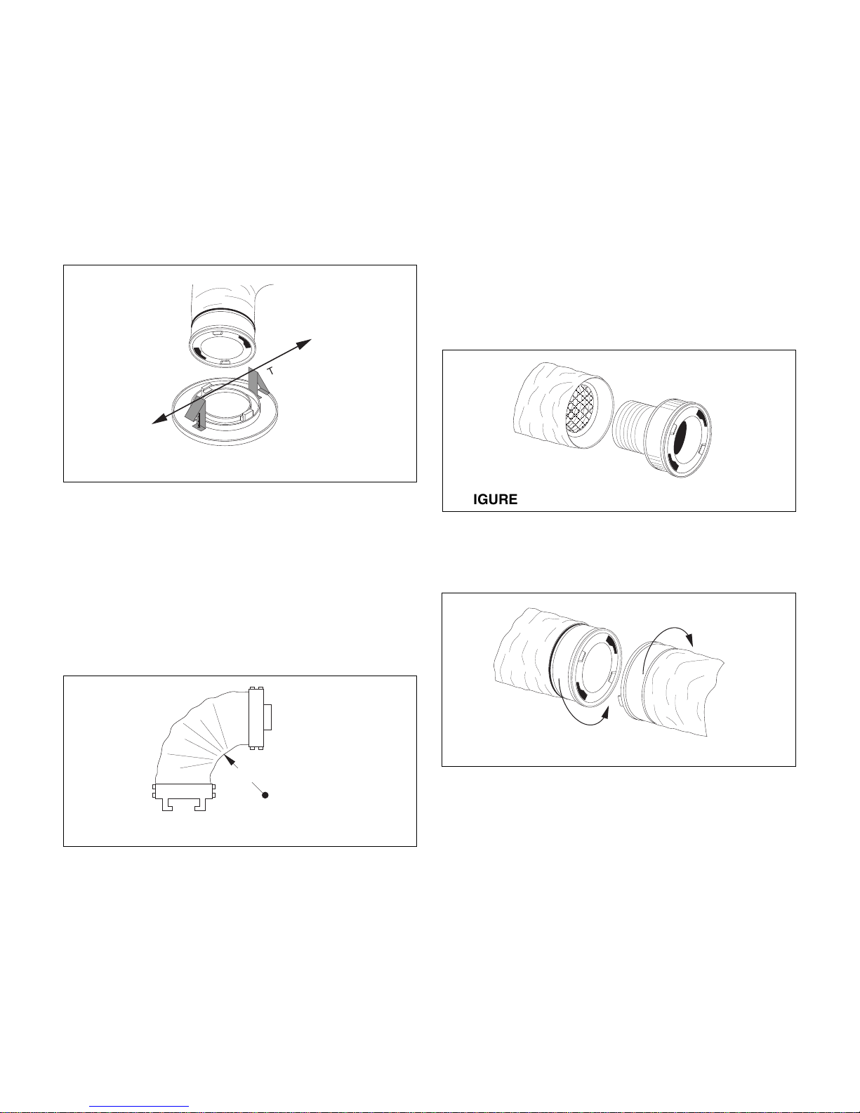
Avoid sharp bends in the supply tubing (as well as the
sound attenuating tube). The minimum radius bend is 4"
(see Figure 2.21); however, wherever possible, hold to a
larger radius.
At the plenum, all supply tubing connections must be
a minimum of 18" from any plenum tee, plenum elbow
or the fan coil unit.
Individual supply tubing runs must be a minimum of
6-feet, even if the distance between the sound attenuating
tubing and plenum is less than 6 feet.
Supply tubing comes in 100-foot sections and may be
cut to length with a knife or fine tooth hacksaw.
For each supply tubing run, estimate and cut the length
of tubing that will be needed between the plenum
and sound attenuating tubing. At the open end of the
supply tubing which will attach to the sound attenuating
tubing, install a kwik-connect (see Figure 2.22). First,
push back the cover and the insulation exposing the inner
core. Second, twist a kwik-connect into the inner core.
Third, pull down the insulation and cover, and tuck it into
the deep groove on the back of the kwik-connect. Fourth,
wrap the connection securely with tape.
When finished, simply twist together (see Figure 2.23)
the kwik-connect on the sound attenuating tube, and
wrap the connection securely with tape.
After attaching the supply tubing to the sound attenuating
tube, bring the open end of the tubing to the plenum.
16
4" MINIMUM RADIUS
FIGURE 2.21: MINIMUM TUBING BEND
FIGURE 2.20: POSITIONING ROOM TERMINATOR
FIGURE 2.22: KWIK-CONNECT INSTALLATION
FIGURE 2.23: CONNECTING TUBING
Center the two spring clips on a line parallel to the
direction of the tubing routing from the room terminator
(see Figure 2.20). This is important since the weight
of the tubing will have a tendency to cause a part of the
terminator to pull away from the ceiling if the clips and
tubing do not run parallel.
Then tighten the screws (attached to the terminator) until
the terminator is snug against the ceiling or floor. Do
not overtighten. For installations with floors or ceilings
which are thicker than normal, longer toggle screws
or special mounting plates may be required.
TUBING ROUTING
Page 17
NOTICE: All four fasteners must be installed to
assure air tight fitting between plenum take-off and
plenum.
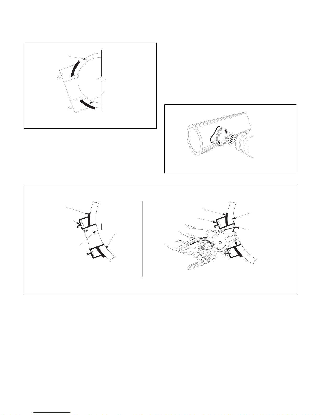
In accordance with your calculations as to requirements
for balancing orifices, mount the orifice in the outlet of
the plenum take-off (see Figure 2.27), prior to attaching
the supply tubing.
Next, install a kwik-connect in the open end of the supply
tubing, using the same procedures as before, and twist
together kwik-connects on supply tubing and plenum
take-off. Wrap connection securely with tape.
Place the plenum take-off gasket on the back side of the
plenum take-off and insert the assembly into the hole in
the plenum (see FIgure 2.25).
NOTICE: Gasket must be installed to seal plenum
take-off to prevent air leakage.
Orient the plenum take-off to match the curvature of the
plenum duct. Hand insert the four plenum take off
fasteners one at a time and using the SpacePak pliers,
snap the fasteners into place until they lock in place (see
Figure 2.26).
17
FIGURE 2.26: PLENUM TAKE-OFF FASTENER INSTALLATION
FIGURE 2.27: ORIFICE INSTALLATION
PLENUM
GASKET
FIGURE 2.25: TAKE-OFF INSTALLATION
GASKET
PLENUM TAKE-OFF
PLENUM
FASTENER
1. HAND INSERT FASTENER INTO PLENUM TAKE-OFF 2. WITH PLIERS, SNAP FASTENER INTO PLACE UNTIL IT LOCKS IN PLACE
PLENUM TAKE-OFF
GASKET
PLENUM
FASTENER
Page 18
18
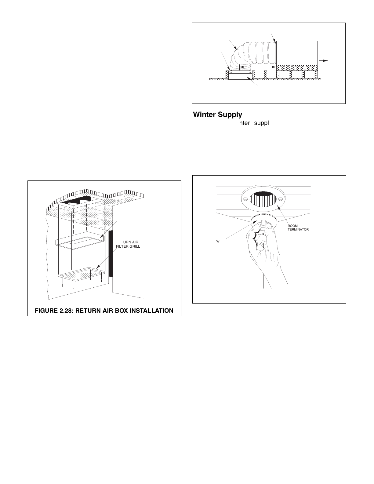
FIGURE 2.29: RETURN AIR DUCT INSTALLATION
FIGURE 2.30: WINTER SUPPLY SHUT-OFF
FIGURE 2.28: RETURN AIR BOX INSTALLATION
Winter Supply Shut-Off Installation
Simply snap winter supply shut-offs into the room
terminator openings (see Figure 2.30). Wrap the return
air filter in a plastic bag and reinstall it to block the return
air opening. Winter supply shut-offs prevent moisture
from collecting in ductwork during winter months. Be sure
to remove the plastic bag and all winter supply shut-offs
before operating the system.
SECTION 3: START-UP & OPERATION
SEQUENCE OF OPERATION
When power is turned on and thermostat fan switch is
set to ON and the cooling indicator is set to OFF, the
indoor fan motor is energized through the normally open
contact FR1 of the FR fan relay in about 30 seconds.
The outdoor unit is off.
When power is turned on and thermostat fan switch is
set to ON or AUTO and the cooling indicator to COOL
the indoor and outdoor units will start through the
normally open contacts FR1 and FR2 of the FR fan relay.
The fan coil unit is equipped with a primary float switch,
the outdoor unit will automatically shut down if the drain
pan is full of water (condensate) and not draining. The
fan coil unit will continue to operate.When the water level
in the drain pan drops, the system will continue normal
operation.
Return Air Box & Duct Installation
Remove the return air grill from the return air box and
remove the air filter from the return air grill.
Insert the return box from below for ceiling installation
(or from the front for wall installations) and fasten with
four screws through holes provided on the long side of
the box. (see Figure 2.28).
Then, insert return air grill into box (see Figure 2.28)
and fasten with the four screws provided through the
holes on both sides. Open return air grill (turn the
1
⁄4turn
latches) and insert filter. Close the return air grill. Slide
a clamp band (provided with return air box) over one end
of the return air duct. Place that end over the elliptical
flange on the fan coil unit (see Figure 2.29). Move the
clamp over the flange and tighten so the clamp holds the
return air duct securely to the flange.
Follow the same procedures to attach the return air duct
to the return air box (see Figure 2.29).
FLEXIBLE RETURN
DUCT (90° BEND)
CLAMP
BAND
CLAMP BAND
48" MIN.
RETURN AIR BOX
SPACE-PAK FAN
COIL UNIT
RETURN AIR
BOX
RETURN AIR
FILTER GRILL
ROOM
TERMINATOR
WINTER
SUPPLY
SHUT-OFF
Page 19
19
PRIOR TO START-UP
1. Check all electrical connections for tightness.
2. Check air filter has been installed in return air box or
filter box.
3. Remove all winter supply shut-offs and store them in
a safe place.
SYSTEM START-UP & ADJUSTMENTS
1. Place thermostat fan switch in ON position and cooling
indicator in OFF position. In about 30 seconds, indoor
unit blower will start.
2. Check blower operation for excess noise or vibration.
3. Check entire distribution system for leakage and apply
additional tape where necessary.
4. Check that system static pressure is within acceptable
limits (minimum 1.0" W.C. - maximum 1.5" W.C.). Static
readings must be taken in the plenum a minimum of 18"
(or after the tee on WCSP-4860D systems) from the fan
coil unit, plenum tees or elbows but before any supply
run.
a. If greater than 1.5" W.C. add additional supply runs.
b. If less than 1.0" W.C. check the return air filter is
clean and return duct is not collapsed or kinked.
c. Check supply air plenum for leaks.
d. If more supply runs than recommended are used,
check that balancing orifices are in place.
5. Check that blower motor amp draw compares with
fan coil unit rating plate. Amp draw shown on plate is the
FLA of motor (not the actual running amps) and will vary
with the pressure and voltage.
6. Place the thermostat cooling indicator in COOL
position, which will start the outdoor unit. Let the system
run at least 30 minutes to stabilize operating conditions.
7. For outdoor unit start-up, follow manufacturer’s
instructions.
8. Check that temperature drop across evaporator coil
in the indoor unit is between 20°F to 28°F.
9. Check the chiller or boiler for proper operation
according to the manufaturer’s instructions.
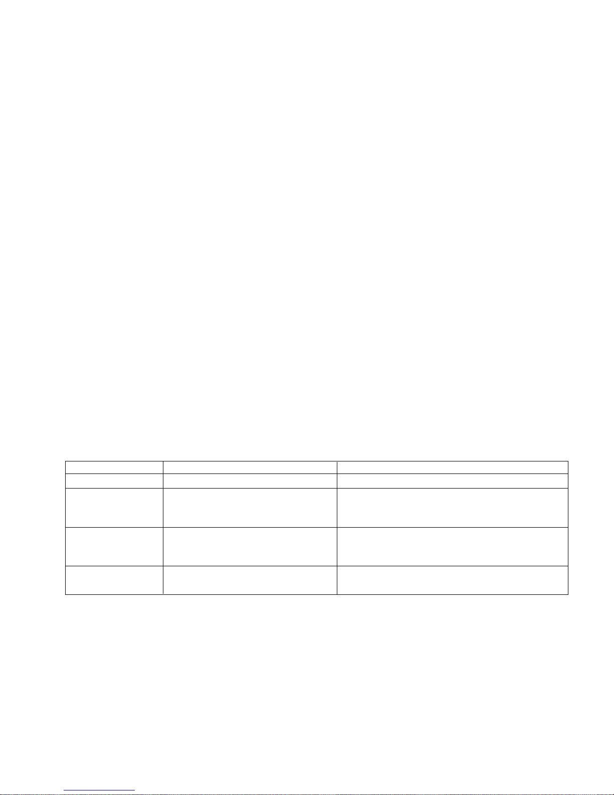
CONDITION VERIFICATION SOLUTION
A. Lack of cooling 1. Chilled water loop temperature 1. Adjust water temperature in chilled water loop
B. Lack of heating 1. Hot water loop temperature 1. Adjust water temperature in hot water loop
C. Blows cold air on 1. Fan is controlled by a thermostat 1. Install aquastat
initial start-up 2. Fan is controlled by an aquastat 2. Adjust setting to allow water loop to reach
proper temperature
D. Condensate does 1. Unit is not level 1. Make sure unit is level
not drain properly 2. Unit is not trapped 2. Install trap supplied with unit
3. Drain line is blocked 3. Clear blockage
E. Unit sweats inside 1. Insulated panels not secured 1. Secure and seal all insulated panels to prevent
cabinet air infiltration
COMMON START-UP CONDITIONS
Page 20
FACTORS AFFECTING THE BALANCE OF THE SYSTEM
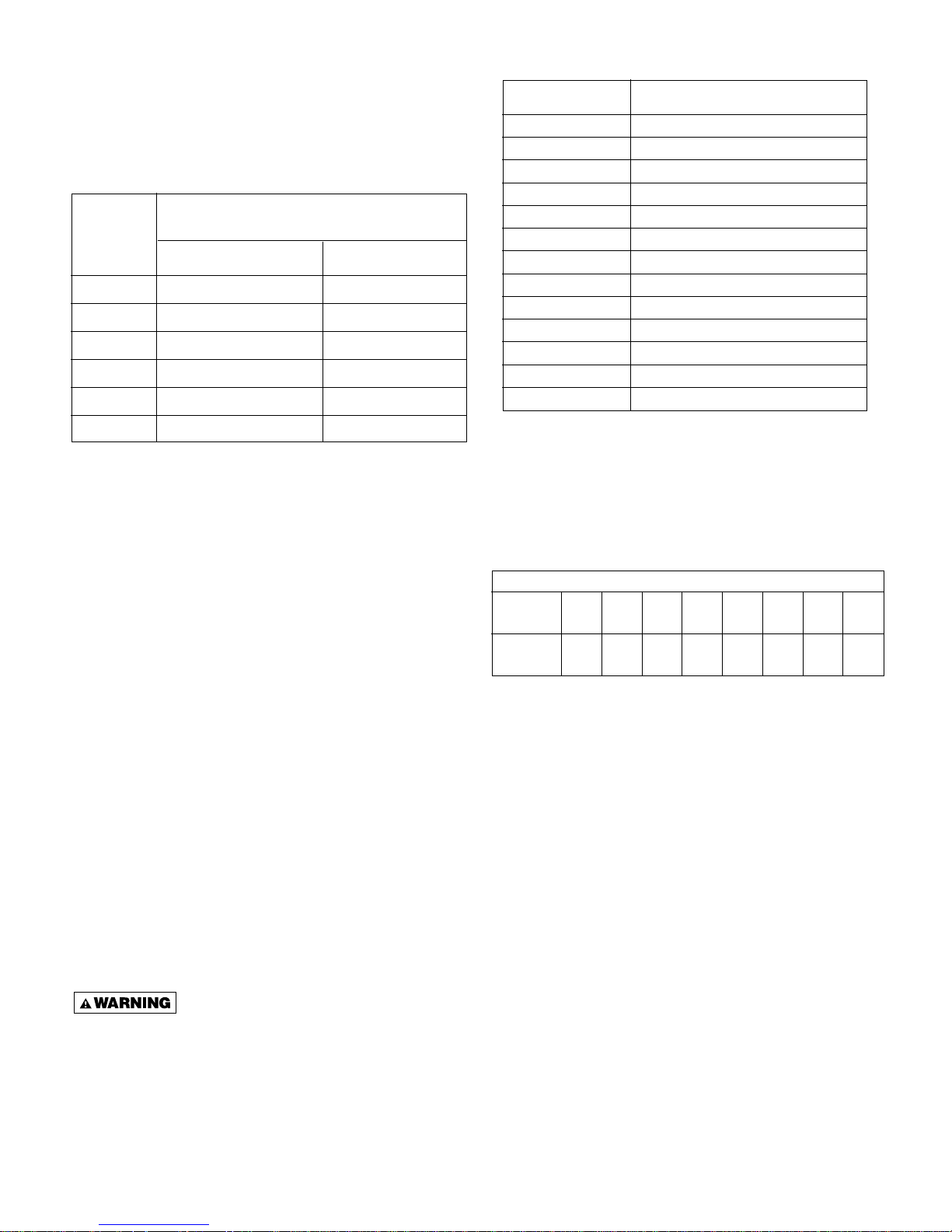
A. Room Terminators (Outlets): Based on the equip-
ment selected, determine the recommended number
of fully open outlets from Figure 3.1.
FIGURE 3.1
B. Orifice Combinations: Should orifices be required to
balance the system (installed at plenum take-off),
refer to the combinations listed in Figure 3.2.
FIGURE 3.2
C. Supply Tubing Length: An outlet with a supply
tubing length of 15 feet is considered one, fully
opened outlet. For other lengths refer to Figure 3.3
for adjustment factors.
FIGURE 3.3
20
SECTION 4: MAINTENANCE
The SpacePak system has been designed to provide
years of trouble-free performance in normal installations.
Examination by the homeowner at the beginning of each
cooling season, and in mid-season should assure
continued, good performance. In addition, the system
should be examined by a qualified service professional at
least once every year.
BEFORE EACH COOLING SEASON
1. Check and clean air filter. The air filter is permanent
type. Remove and clean thoroughly with soap solution
and water.
Turn off electrical power supply
before servicing. Contact with live electric components can cause shock or death.
2. Check fan coil unit. Turn off unit power disconnect
switch and remove service access panels.
a. Inspect coil and blower wheel for build-up of dust
and dirt. Clean with solvent and/ or water as necessary.
b. Replace service access panels and turn on unit
power disconnect switch.
3. Check that unit condensate drain is clear and free
running, and plug is in cleanout.
4. For chiller or boiler unit, follow manufacturer’s maintenance instructions.
5. Follow “System Start-Up & Adjustments” procedures
in Section 3 of this manual.
IF SYSTEM FAILS TO OPERATE
1. Check that thermostat switch is set for proper mode
of operation and is set below room temperature.
2. Check that chiller or boiler unit is operating.
3. Check for tripped circuit breaker or blown fuse at
the main fuse box. Reset breaker or replace blown fuse
with same size and type.
MINIMUM RECOMMENDED
NUMBER OF FULLY OPEN OUTLETS *
NOMINAL
TONNAGE
2
2 1/2
3
3 1/2
4
5
* The minimum or recommended number of outlets means fully open outlets. Any
outlet having an orifice would be only a percentage of an outlet.
MODEL
WCSP-2430D
WCSP-2430D
WCSP-3642D
WCSP-3642D
WCSP-4860D
WCSP-4860D
RECOMMENDED
12
14
17
19
26
26
DESIRED NUMBER
OF TERMINALS *
.5
.65
.85
1.00
1.15
1.30
1.50
1.65
1.70
1.80
1.85
1.95
2.00 (2)
* For a room with more than two (2) terminals, combinations of the above
may be used to achieve the desired fractional number.
(1) .5
(1) .35
(1) .15
(1)
(1) .5 + (1) .35
(2) .35
(1) .35 + (1) .15 or (1) + (1) .5 or (3) .5
(1) + (1) .35 or (2) .5 + (1) .35
(2) .15
(2) .35 + (1) .5
(1) + (1) .15
(3) .35
TERMINAL - ORIFICE
COMBINATION
2" SUPPLY TUBING LENGTH ADJUSTMENT FACTOR CHART
RUN
FACTOR
6' 8' 10' 12' 15' 20' 25' 30'
.85 .88 .90 .94 1.0 1.1 1.25 1.50
Page 21
21
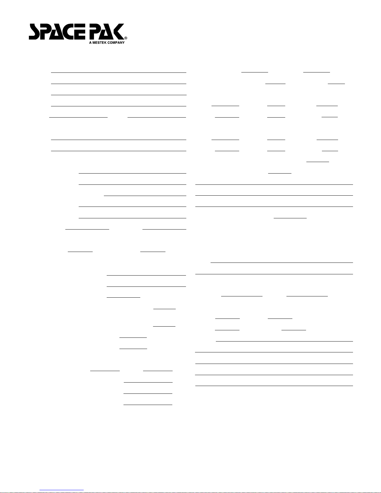
Customer / Dealer Data:
Name:
Address:
Tel (day) (eve)
Installing Dealer / Contractor:
Name:
Tel:
Equipment Data:
SPACEPAK Model #
ESP / WCSP -
SPACEPAK Serial #
SPACEPAK Date of Installation:
Cond Unit Mfr:
Cond Unit Mod #:
Rated Capacity:
BTUH
; SEER:
Air-side Data:
Total # of outlets: ; Supply tube length: Ft (avg)
(Please sketch duct layout on reverse side of this sheet, noting all fittings
and distances, including return duct size / length)
Air Filter: Size (LxHxD)
Type (pleated, etc):
Is the filter clean? (Y/N)
Static Pressure (Ps) in supply plenum: "WG
(Measure at approximately 3 ft downstream of blower discharge)
Ps in return duct (downstream of filter, upstream of coil) "WG
SpacePak Motor: Amps (measured): Amps
Voltage (measured): Volts
Air Temperatures:
@ Return (indoor ambient): °FDB; °FWB
@ Condensing unit (outdoor ambient): °F
@ AHU (read 3 ft from fan discharge) °F
@ last supply outlet °F
Refrigeration-side Data:
Line sizes: Liquid Suction
Total equivalent length of lines: Ft; Vertical Rise: Ft.
@ Condensing Unit:
Liquid: psi; Temp: °F; Subcool: °F
Suction: psi; Temp: °F; Superheat: °F
@SpacePak:
Liquid: psi; Temp: °F; Subcool: °F
Suction: psi; Temp: °F; Superheat: °F
Approximate time running before taking readings: Hrs.
Did you adjust the TXV? (Y/N); (If yes, explain):
Refrigerant Charge (if weighed-in): lbs
R410a / R22 (circle one)
Installed options: (circle one)
sight glass filter/drier zone controls
Other:
Water Data:
(where applicable)
Line sizes: "; Length: FT
Water temperatures:
Suppy: °F; Return °F
Glycol?: (Y/N); % Solution:
NOTES:
Service / Troubleshooting FORM “1A”
Page 22
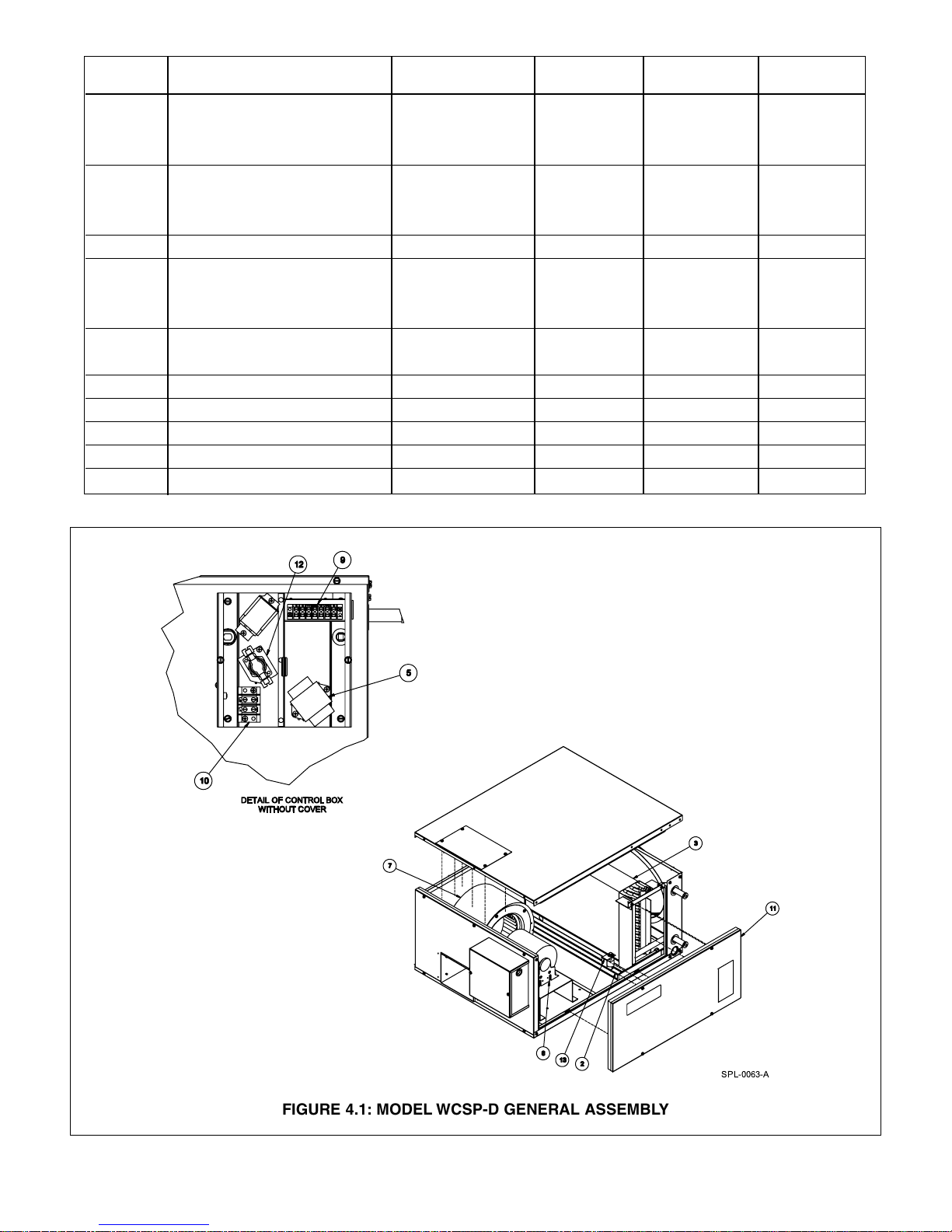
REF.
NAME OF PART PART NO. WCSP-2430D WCSP-3642D WCSP-4860D
NO.
2
Drain Pan Assembly BM-7354 1
Drain Pan Assembly BM-7355 1
Drain Pan Assembly BM-7356 1
3
Coil Assembly 70-8021 1
Coil Assembly 70-8022 1
Coil Assembly 70-8023 1
5 Transformer 27-3293 1 1 1
6
Motor 27-3236 1
Motor 27-3237 1
Motor 27-3238 1
7
Blower Wheel 27-8032 1 1
Blower Wheel 27-8033 1
9 Terminal Block (low volt) 27-3051 1 1 1
10 Terminal Block (high volt) 27-3056 1 1 1
11 Access Panel BM-7361 1 1 1
12 Fan Relay 27-3322 1 1 1
13 Primary Float Switch BM-6917 1 1 1
22
FIGURE 4.1: MODEL WCSP-D GENERAL ASSEMBLY
Page 23

23
NOTES:
Page 24

LIMITED WARRANTY
Central Air Conditioning Products
The “Manufacturer” warrants to the original owner at the original installation site that the Central Air
Conditioning Products (the “Product”) will be free from defects in material or workmanship for a period not to
exceed one (1) year from the startup or eighteen (18) months from date of shipment from the factory, whichever
occurs first. If upon examination by the Manufacturer the Product is shown to have a defect in material or
workmanship during the warranty period, the Manufacturer will repair or replace, at its option, that part of the
Product which is shown to be defective.
This limited warranty does not apply:
a) if the Product has been subjected to misuse or neglect, has been accidentally or intentionally
damaged, has not been installed, maintained or operated in accordance with the furnished written
instructions, or has been altered or modified in any way.
b) to any expenses, including labor or material, incurred during removal or reinstallation of the defective
Product or parts thereof.
c) to any workmanship of the installer of the Product.
This limited warranty is conditional upon:
a) shipment, to the Manufacturer, of that part of the Product thought to be defective. Goods can only be
returned with prior written approval from the Manufacturer. All returns must be freight prepaid.
b) determination, in the reasonable opinion of the Manufacturer, that there exists a defect in material or
workmanship.
Repair or replacement of any part under this Limited Warranty shall not extend the duration of the warranty with
respect to such repaired or replaced part beyond the stated warranty period.
THIS LIMITED WARRANTY IS IN LIEU OF ALL OTHER WARRANTIES, EITHER EXPRESS OR IMPLIED,
AND ALL SUCH OTHER WARRANTIES, INCLUDING WITHOUT LIMITATION IMPLIED WARRANTIES OF
MERCHANTABILITY OR FITNESS FOR A PARTICULAR PURPOSE, ARE HEREBY DISCLAIMED AND
EXCLUDED FROM THIS LIMITED WARRANTY. IN NO EVENT SHALL THE MANUFACTURER BE LIABLE
IN ANY WAY FOR ANY CONSEQUENTIAL, SPECIAL, OR INCIDENTAL DAMAGES OF ANY NATURE
WHATSOEVER, OR FOR ANY AMOUNTS IN EXCESS OF THE SELLING PRICE OF THE PRODUCT OR
ANY PARTS THEREOF FOUND TO BE DEFECTIVE. THIS LIMITED WARRANTY GIVES THE ORIGINAL
OWNER OF THE PRODUCT SPECIFIC LEGAL RIGHTS. YOU MAY ALSO HAVE OTHER RIGHTS WHICH
MAY VARY BY EACH JURISDICTION.
 Loading...