

Page 1
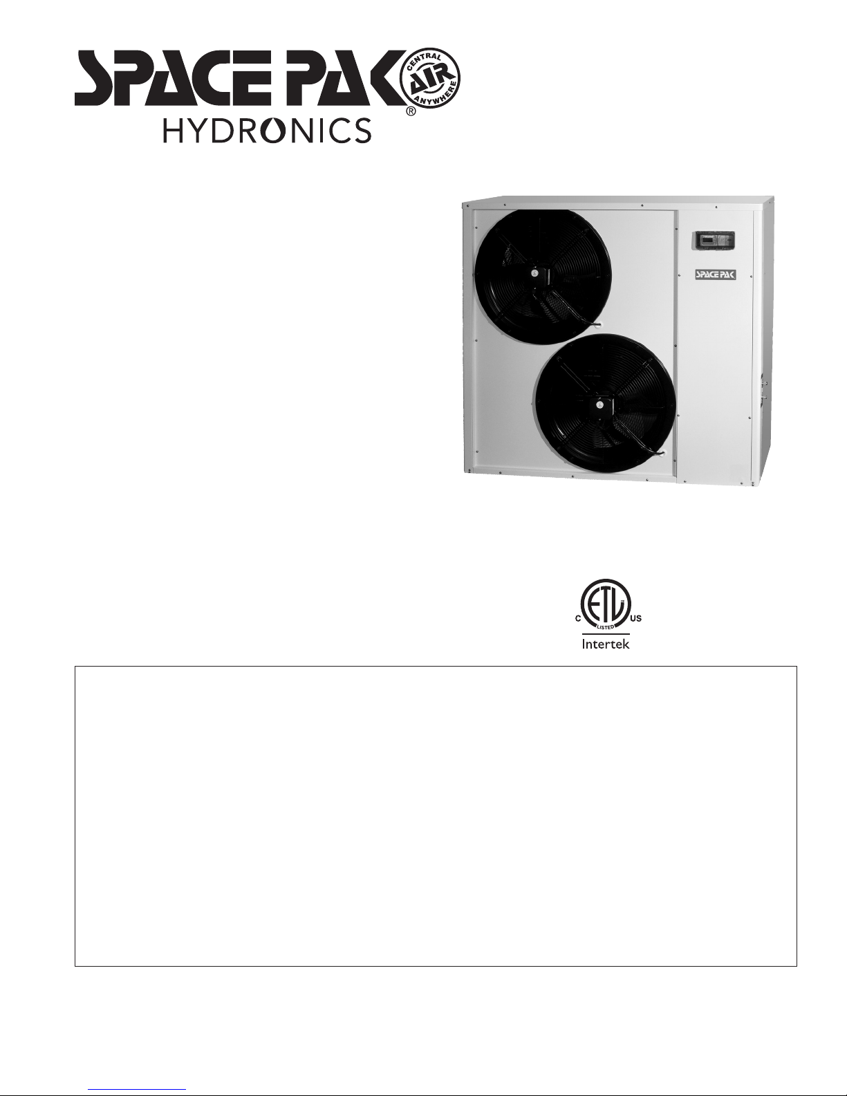
MODEL LAHP48
INSTALLATION,
OPERATION
& MAINTENANCE
MANUAL
Low Ambient Air to Water
Reverse Cycle Heat Pump
LAHP2-1016
45W30-WG0773
SECTION 1: READ BEFORE PROCEEDING
Model LAHP Overview ................................................................ 2-3
SECTION 2: SPECIFICATIONS AND RATINGS ................. 4
SECTION 3: DIMENSIONS ...................................................... 5
SECTION 4: LOCATION & MOUNTING
Prepare the Unit .......................................................................... 6
Location ....................................................................................... 6
Hoisting ....................................................................................... 6
Mounting Pad .............................................................................. 6
Indoor Installation ........................................................................ 7
SECTION 5: MINIMUM REQUIRED SYSTEM
COMPONENTS ................................................... 7
SECTION 6: GLYCOL/WATER SYSTEM
Glycol/Water System Design/ Installation .................................... 8-9
SECTION 7: START-UP AND TEST
Preparing for Start-Up ................................................................. 9
BEFORE Starting the Unit ........................................................... 10
Start the SpacePak Low Ambient Heat Pump ............................. 10
Anti-freeze Cycle ......................................................................... 10
24-Hour follow-up ........................................................................ 10
IN UNITED STATES: 260 NORTH ELM ST. WESTFIELD, MA 01085 800-465-8558 / FAX (413) 564-5815
IN CANADA: 7555 TRANMERE DRIVE, MISSISSAUGA, ONTARIO, L5S 1L4 (905) 670-5888 / FAX (905) 670-5782
SECTION 8: ELECTRICAL DIAGRAMS
Field Connections ........................................................................ 11
Pictorial Diagram ......................................................................... 12
Ladder Diagram ........................................................................... 13
SECTION 9: TROUBLESHOOTING/FAULT CODES ......... 14-15
SECTION 10: MAINTENANCE
Annual Inspection ........................................................................ 16
Preparing the LAHP for Shut Down ............................................. 16
To Restart After Shutdown ........................................................... 16
SECTION 11: REPLACEMENT PARTS ................................ 17
SECTION 12: LIMITED WARRANTY ..................................... 18
Copyright 2016 Mestek, Inc.
Page 2
Model LAHP48 Air to Water Heat Pump — Installation, Operation & Maintenance Manual
Qualified installer only —
This product must be installed only by a qualified
service technician. The installation must be done
using recognized industry practices, and in
compliance with this manual and all applicable
codes. Failure to comply could result in death,
serious injury or substantial property damage.
Section 1: READ BEFORE PROCEEDING
For information not included in this manual,
see the following: This manual includes only basic
information for installation, operation and maintenance of SpacePak air to water heat pumps. For
more advanced applications and information not
shown in this manual, contact SpacePak Technical
Support for assistance and supplemental instruc-
tions. Call 413-564-5530 in Westfield, MA or visit
our website at www.spacepak.com to send an
email or review technical literature.
Hazard Definitions
The following terms are used throughout this manual to bring
attention to the presence of potential hazards or to important
information concerning the product.
Indicates an imminently hazardous situation, which
if not avoided, WILL result in death, serious injury or
substantial property damage.
Indicates an imminently hazardous situation, which
if not avoided, COULD result in death, serious
injury or substantial property damage.
Indicates an imminently hazardous situation, which
if not avoided, MAY result in minor injury or property
damage.
Used to notify of special instructions on installation,
operation or maintenance, which are important to
equipment, but not related to personal injury hazards.
Model LAHP Overview
The SpacePak Model LAHP48 Low Ambient Heat Pump is a selfcontained reverse cycle heat pump that provides a continuous
supply of heated or chilled water for various purposes, such as:
residential or small commercial building heating and cooling;
and specialty applications, such as computer room cooling or
industrial/agricultural conditioning and dehumidification.
The Major Components of the LAHP48 are:
Model LAHP Heat Pumps are specifically configured to provide
water at 113-140°F (45-60°C) at ambient temperatures as low
as -8°F (-22°C) for medium temperature hydronic heating in
moderate to cold winter climates. Additionally, cooling capacity
of four tons is available in summer conditions up to 95°F (35°C).
• A hermetically sealed, Enhanced Vapor Injected scroll
refrigeration compressor & motor. The Enhanced Vapor
Injection system draws heat from the liquid refrigerant,
subcooling the charge for maximum heat capacity under
extreme cold conditions, and uses that heat energy to
increase the compression, and therefore usable heat,
produced by the compressor.
• A generously sized outside coil to absorb heat (in heating
mode) from the surrounding ambient air, or reject heat (in
cooling mode).
• Two variable-speed motorized fans to force air through the
outside coil.
• A brazed-plate refrigerant-to-water heat exchanger to supply
heat (in heating) to the delivered water flow, or absorb heat
(in cooling).
• A dedicated thermal expansion valve to throttle the refrigerant
flow in heating and an electronically controlled expansion
valve to manage Vapor Injection operation, responding to
varying load on the system.
• Additionally, the system contains a reversing valve (to select
between heating and cooling operation) and sensors and
safety circuits to monitor and protect the equipment from
potentially damaging or dangerous operating conditions.
The water circuit passes through the internal brazed-plate heat
exchangers, and contains sensors to measure entering and
leaving water temperatures. A mechanical flow switch safety
ensures continuous water flow while the refrigerant system is
operating.
All components are contained within a supporting structure and
enclosure sufficient to allow stand-alone outdoor installation in
all temperate climates.
All operation and protections are managed by a microprocessor
controller which operates the individual systems, determines
all operating parameters, and monitors the condition of each
system. A simple interface communicates with the indoor air
handler, heat exchanger, or other load.
Codes and Electrical Requirements
• This product must be installed in accordance with all
applicable codes. Where instructions in this manual differ
from specific local requirements, defer to the local codes.
• The electrical installation must also comply with the latest
edition of: in the U.S. — National Electrical Code ANSI/NFPA
No. 70; in Canada — CSA C22.1 Canadian Electrical Code
Part 1. Wiring must be N.E.C. Class 1. Use only copper wire,
rated for 90°C (194°F) and sized for the load listed in this manual.
• Electrical shock hazard — Disconnect all electrical power
before servicing the unit. Also, the unit must be grounded in
accordance with the Electrical Code listed above.
Refrigerant
• The refrigeration system is factory charged with R410A
refrigerant, and requires no additional service during
installation. Any repair, diagnosis or maintenance service
to the refrigeration system must be performed by a qualified
technician. No alternate refrigerants, lubricants or additives
are approved for this unit. Any use of alternate or nonapproved materials in the refrigeration system may result in
personal injury or equipment damage, and will void the
manufacturer’s warranty.
– 2 –
Page 3
Model LAHP48 Air to Water Heat Pump — Installation, Operation & Maintenance Manual
Liquid Side
The fluid in the liquid side of the Model LAHP
must be an anti-freeze/water mix. Only Ethylene
Glycol or Propylene Glycol anti-freeze mixtures
specifically formulated for boiler or hydronic system
use are allowed.
The use of automotive glycol anti-freeze, or any alternative
such as methanol or glycerin, will immediately void the
manufacturer’s warranty.
• The antifreeze percentage must be at least 30% by volume.
This will ensure a free flowing coolant loop down to and
below the minimum operating envelop, as well as burst
protection to at least -60°F (-51°C). Therefore, a higher
concentration is not generally recommended. However, if it is
absolutely necessary to be able to “cold start” (after power
has been removed and all components have cooled to
ambient temperature) the coolant loop in extreme conditions,
it is allowable to use up to a 50% glycol solution, for free flow
down to -40°F (-40°C), though it should be noted that the
heat transfer capacity of this higher concentration is lower,
and the viscosity (system pressure drop) is significantly
higher, so the unit performance will be diminished accordingly,
and the circulator choice must be appropriate for these
conditions.
Thoroughly flush the system before filling.
• The system must be supplied with a pump sized to provide
the minimum flow rates specified in this manual. Pump
selection must consider the pressure loss through the
system and its components plus the pressure loss through
the LAHP’s heat exchanger and internal components. The
pump must be rated for use with chilled water/glycol mixture.
• Install a y-strainer at the liquid input of the heat pump as
shown in this manual to prevent damage to the heat
exchanger from sediment.
• DO NOT use for potable water heating. The single-wall heat
exchanger is not suitable for the application.
Ambient Operating Limits
• The LAHP48 is designed to deliver optimal performance in
ambient temperatures ranging from -8°F (-22°C) to 95°F
(35°C). Operation outside of these limits is not prohibited,
as internal protective circuits will prevent dangerous or
destructive conditions. However operation outside of this
range will result in significantly diminished performance and
may result in spontaneous shut down of the heat pump if the
protective safety features are engaged.
LAHP Controller
The LAHP electronic controller allows the adjustment of basic
Control Setpoints
• HEATING temperature
• COOLING temperature
• Temperature DIFFERENTIALS
These setpoints can be adjusted at installation or by the
homeowner at any time. Contact SpacePak Technical Support
for assistance if more advanced set up is desired.
Standard Equipment
• Heat pump, including a refrigeration system, factory-programmed controller, fans and all required internal components
• Powder-coated enclosure
• Pump and piping by others
Additional Components Required
• Expansion tank, properly sized for system volume
• SpacePak Heat Pump Interface Module.
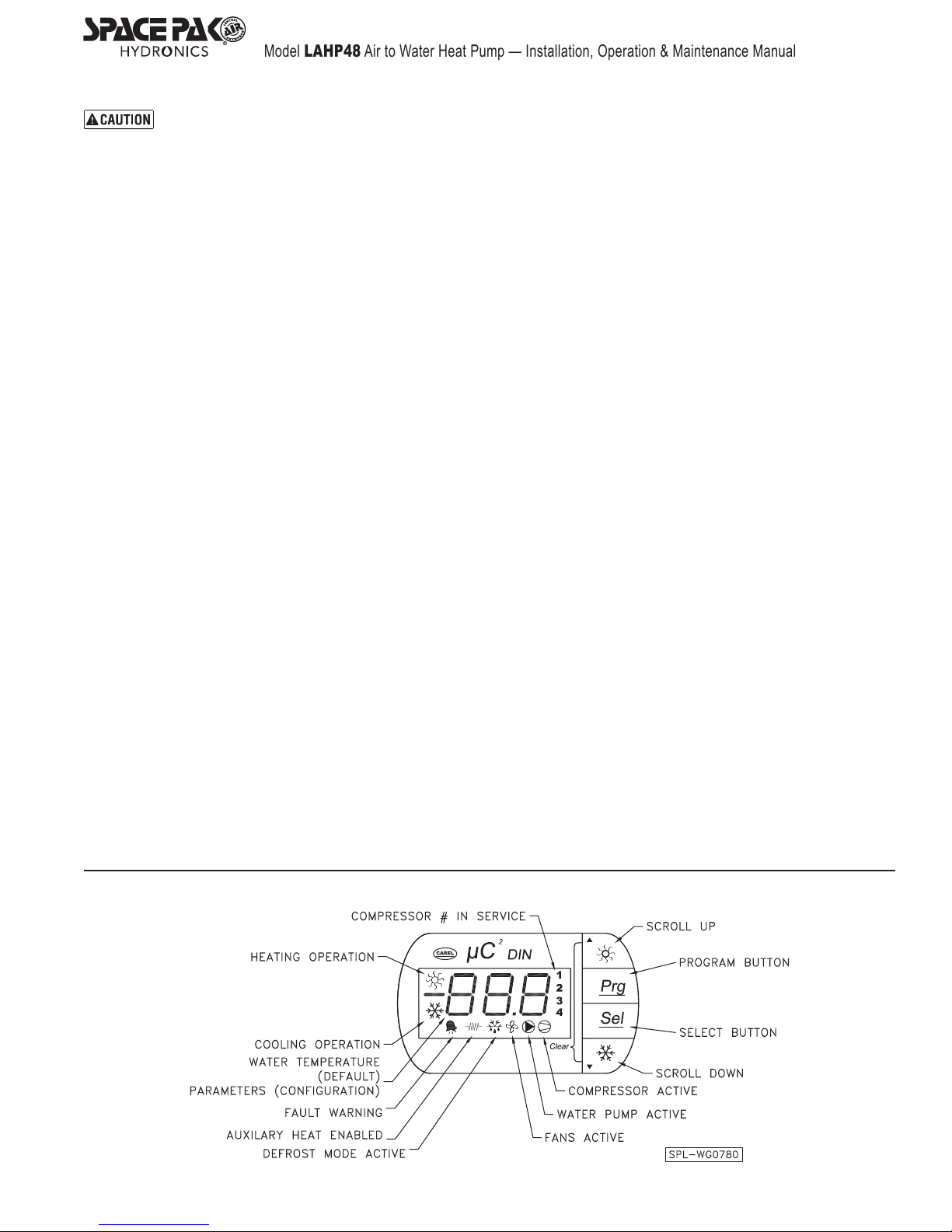
Figure 1 LAHP Controller
– 3 –
Page 4
Model LAHP48 Air to Water Heat Pump — Installation, Operation & Maintenance Manual
Section 2: Specications & Ratings
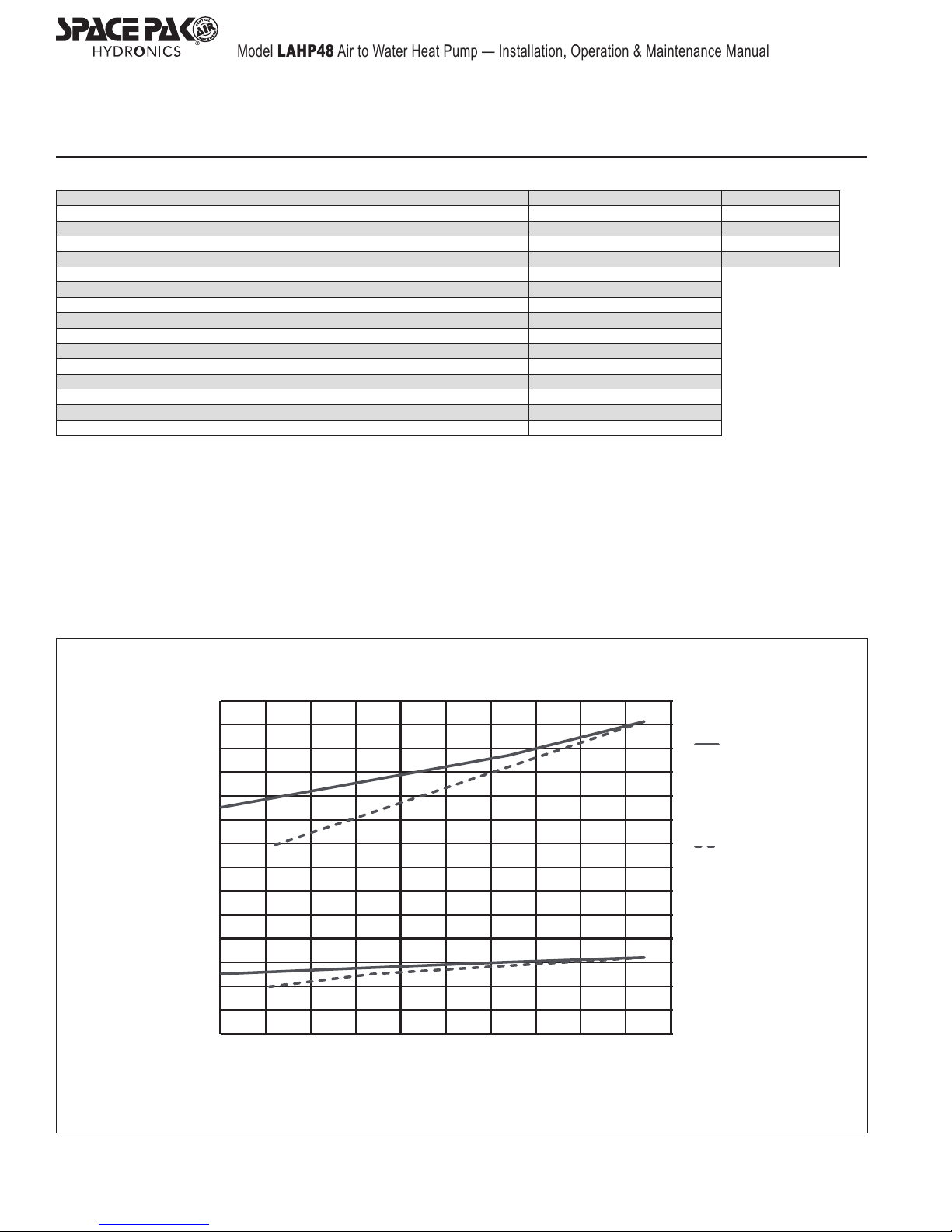
Figure 2
Model LAHP - 048 COP
Heating Capacity (47°F Ambient, 120°F Supply Water) 64,680 BTUh (18.9 kW) 3.18
Heating Capacity (17°F Ambient, 120°F Supply Water) 46,440 BTUh (13.6 kW) 2.35
Heating Capacity (5°F Ambient, 120°F Supply Water) 39,240 BTUh (11.5 kW) 2.35
Cooling Capacity (95°F Ambient, 44°F Supply Water) 40,000 BTUh (11.7 kW) 2.43
Voltage 230V/1ph/60Hz
Min Supply Temp 42°F (5.5°C)
Max Supply Temp 125°F (52°C)
Min Water Flow 10 GPM (37.8 I/min)
Nominal Water Flow 12 GPM (45.4 I/min)
dP@ Max Flow 17.2 ft (35.8 kPa)
Heating Current 31 Amps
Cooling Current 23.5 Amps
Noise Level 62 dB (A)
Compressor Scroll
Installed Weight 386 lbs (175 Kg)
LAHP Heating Performance
70000
60000
50000
40000
30000
BTU at 120°F LWT
20000
10000
0
0510 15 20 25 30 35 40 45 50
Outdoor Ambient °F
Heating performance at Ambient temperature and 120°F water supply
*Peak performance is steady state without capacity drop due to frosting and/or defrosting
‡Tested performance is per AHRI 550/590 including frosting/defrosting affect.
14
13
12
11
10
9
8
7
6
5
4
3
2
1
0
*Peak
‡Tested
COP
– 4 –
Page 5
Model LAHP48 Air to Water Heat Pump — Installation, Operation & Maintenance Manual
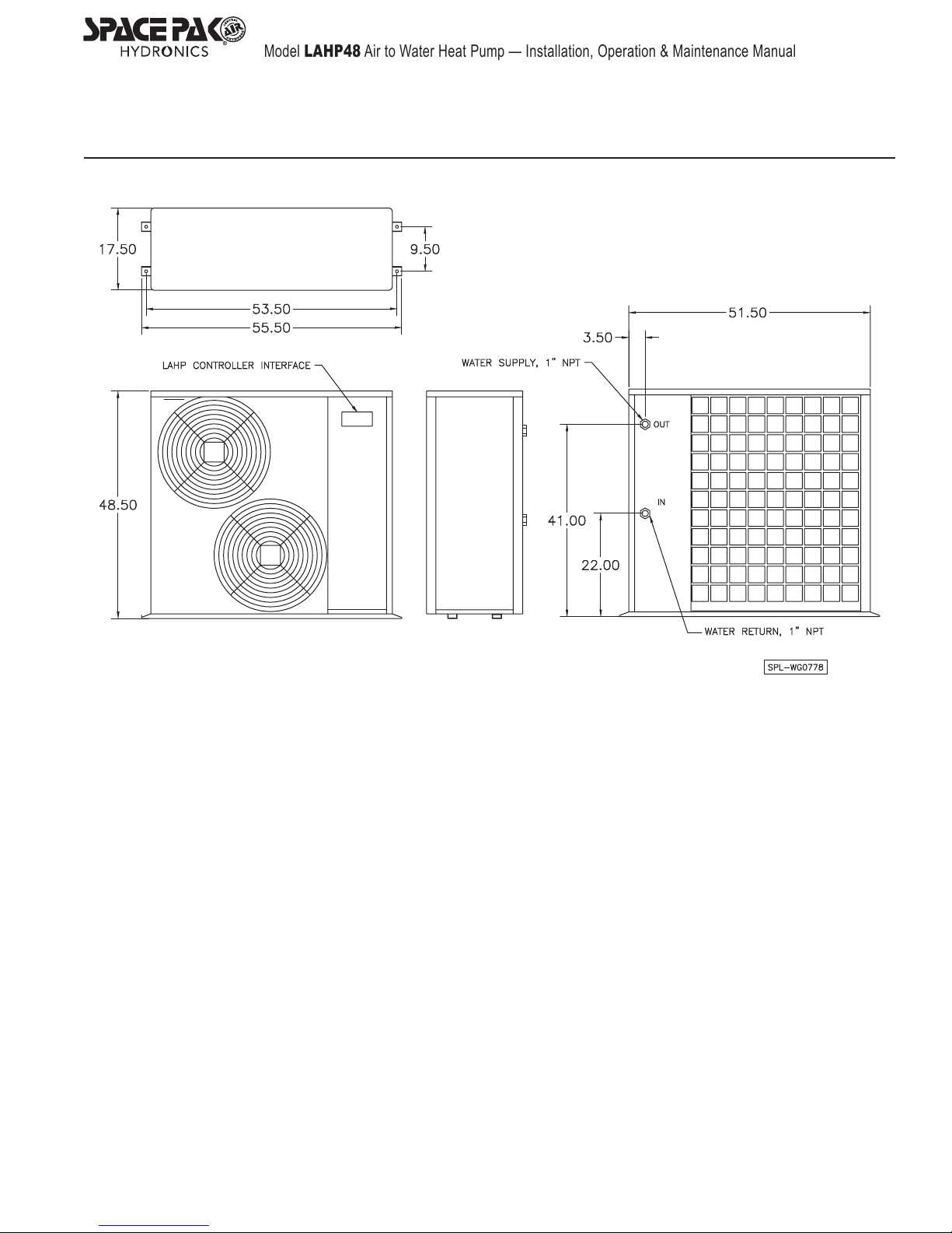
Section 3: Dimensions
Figure 3 Model LAHP Dimensions (all dimensions in inches)
– 5 –
Page 6
Model LAHP48 Air to Water Heat Pump — Installation, Operation & Maintenance Manual
Section 4: Location & Mounting
Failure to comply with all of the guidelines IN THE
FOLLOWING could result in death, serious injury or
substantial property damage.
The installation must comply with all applicable local codes.
Prepare The Unit
Inspect the unit for shipping damage. DO NOT use if there is a
risk that the damage could affect unit operation.
Make sure all required components are available.
Install optional immersion heater, if used. See instructions
provided with the heater.
Location
• DO NOT locate where the unit could be sprayed by sprinklers.
• DO NOT locate near swimming pools, spas or any location
that could cause chlorine or other contaminant to enter the
unit.
• DO NOT locate where water run-off from adjacent structures
could impinge on the unit.
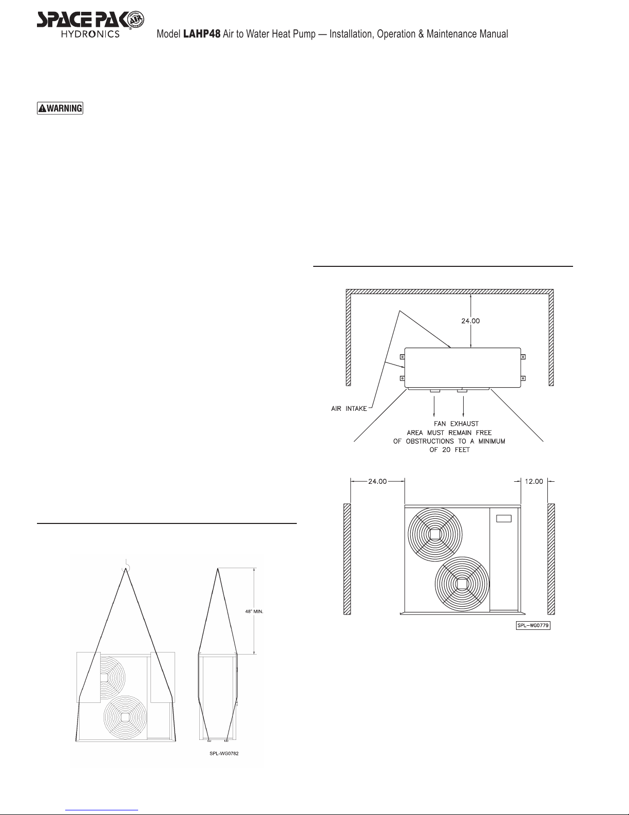
• Maintain the clearances shown in Figure 5.
Hoisting (refer to Figure 4)
Using four equal length straps or cables, route them from the
mounting feet, in front of and behind the cabinet, and join them
together no less than 48" above the top of the unit.
This is ideally done in the original packaging, but if the unit
has been unpacked, ensure the cabinet is protected where the
cables cross, with sufficient padding such as multiple layers or
corrugated cardboard.
Use caution when handling. The unit is heavy and could cause
severe injury or damage if dropped or handled incorrectly.
Mounting Pad
The SpacePak heat pump must be mounted on a level corrosion
and weather-resistant mounting surface, preferably concrete.
The structural support must be suitable for the operating weight
of the unit and attached components, its mounting pad, snow
loading and any other expected loads.
There must be sufficient clearance all around the LAHP for
proper performance. Refer to Figure 5 for clearance dimensions.
The mounting pad must not be attached directly to a structure
where noise transmission would be objectionable.
Vibration isolators supplied with the chiller may be installed
when desired to reduce transmitted vibration.
Figure 5 Maintain Clearances Shown Above
Figure 4 Hoisting
The unit must be bolted securely to the pad. Where required by
local jurisdiction, the mounting must also be analyzed for seismic
loading capability.
The mounting must ensure that there will be no debris accumu-
lation which might block air flow through the enclosure openings.
The lower edge of the lower fan opening must be above the
typical snow line, including allowance for drifting.
There must be no accumulation of water that could reach the
bottom of the unit’s enclosure.
– 6 –
Page 7
Model LAHP48 Air to Water Heat Pump — Installation, Operation & Maintenance Manual
Section 4: Location & Mounting (continued)
Corrosive Environments
Do NOT install the unit in an area subject to sea air or other
potential corrosive contaminants.
Indoor Installation
If the unit is installed inside a building, the building must be
equipped with air openings sufficient to ensure free discharge of
heated (or cooled) air generated by the heat pump. All clearances
must be maintained to ensure free air flow into and out of the
enclosure. Make sure no other equipment located in the space
will be affected by the units air flow.
All clearances must be maintained to ensure free air flow into
and out of the enclosure. Make sure no other equipment located
in the space will be affected by the unit’s airflow.
Section 5: Minimum Required System Components
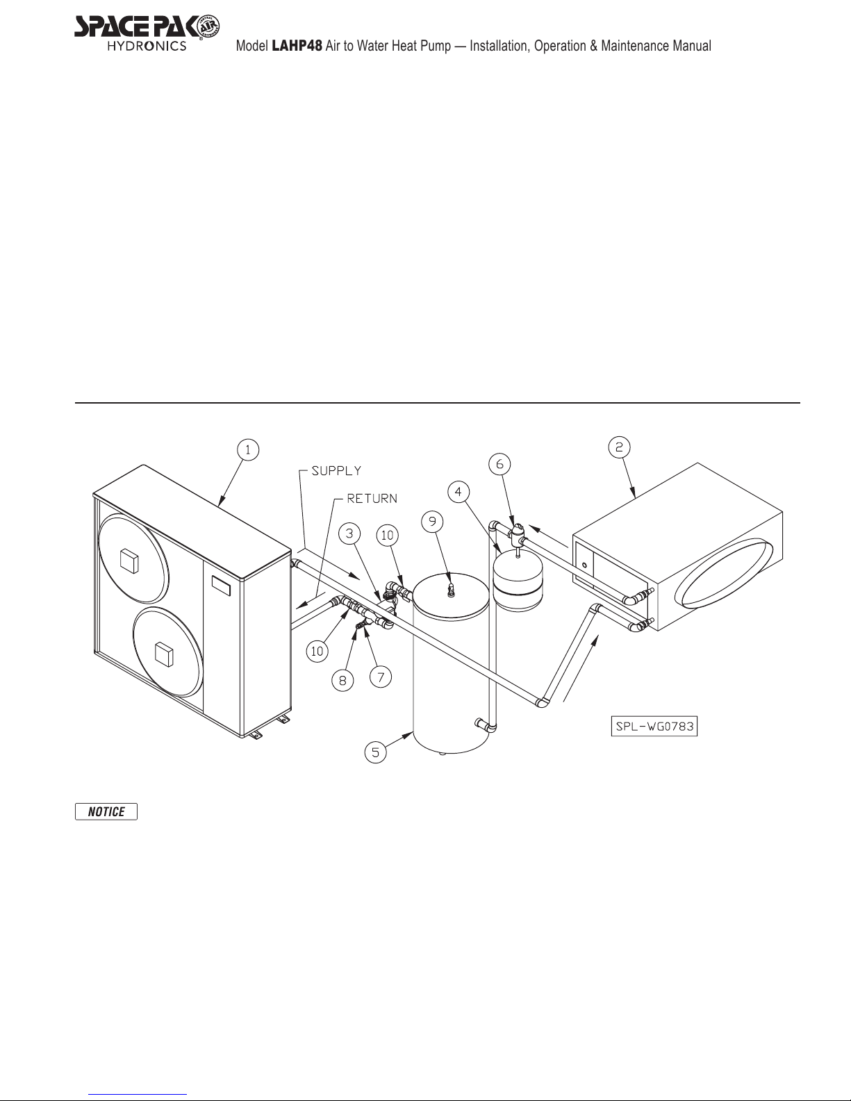
Figure 6
Every installation will vary; this graphic illustrates the minimum components required on every installation to ensure
satisfactory performance and durability.
1 SpacePak LAHP48 heat pump
2 Heat emitter(s), air handler, convector, radiant panel or radiant
grid
3 Circulator/Pump, selected specific to installation
4 Expansion Tank, diaphragm type, sized for specific system
volume
5 Buffer tank, sized according to loads and zoning
6 Air Separator
7 Y-strainer
8 Drain Valve/Port
9 Pressure Relief Valve (maximum rating, 40 PSIG)
10 Isolation Valves, for pump or Strainer service
11 Manual Purge Valve (not shown) typically included in the heat
emitter, otherwise, must be installed at the highest point in the
system.
– 7 –
Page 8
Model LAHP48 Air to Water Heat Pump — Installation, Operation & Maintenance Manual
Section 6: Glycol/Water System
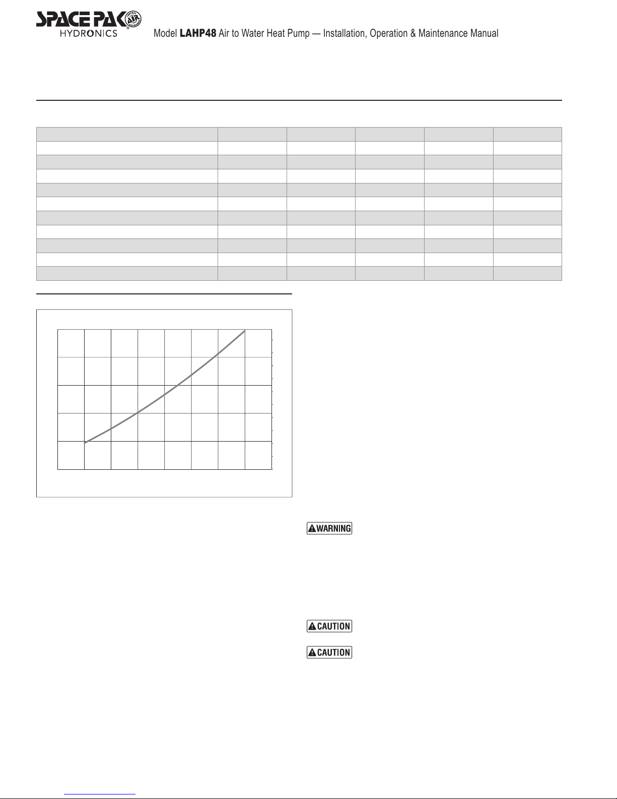
Figure 7 LAHP Glycol Concentrations (30% Minimum, 50% Maximum)
Ethylene Glycol % 10 20 30 40 50
Min. Ambient Temp 23°F/5°C 14°F/10°C 2°F/-17°C -13°F/-25°C -36°F/-38°C
SpacePak Capacity Multiplier 0.98 0.96 0.93 0.91 0.89
Pressure Drop Multiplier (COOLING) 1.06 1.12 1.16 1.25 1.36
Pressure Drop Multiplier (HEATING) 1.06 1.12 1.16 1.22 1.28
Propylene Glycol % 10 20 30 40 50
Min. Ambient Temp 26°F/3°C 18°F/8°C 8°F/-13°C -7°F/-22°C -29°F/-34°C
SpacePak Capacity Multiplier 0.99 0.98 0.96 0.93 0.88
Pressure Drop Multiplier (COOLING) 1.10 1.20 1.34 1.50 1.65
Pressure Drop Multiplier (HEATING) 1.10 1.20 1.34 1.46 1.50
Figure 8
30
25
20
Ft WC
15
10
5
7 89101112131415
LAHP Glycol Head Loss
Measured with 30% Propylene Glycol at 120 deg F
Liquid Flow GPM
12
11
10
9
PSI
8
7
6
5
4
3
2
Glycol/Water System Design
Size the Piping and Select the System Pump
Using the flow rate and pressure drop given in Figure 8, size
the system piping and pump accordingly. Adjust the pressure
drop through piping and heat pump using the glycol correction
multipliers in Figure 7.
System Volume and Expansion Volume
To ensure smooth temperature control and minimize cycling of
refrigeration system, all installations must have total volumes
equal to or greater than five gallons per nominal ton of the unit
performance (The greater of either heating or cooling produced).
In other words, in the case of a four ton heat pump the minimum
total system volume is 4x5=20 gallons. Multiple heat pump
installations that are operating in a staged configuration follow
the same rule, so that only a single heat pump tonnage needs
to be considered. Additionally, the system requires an expansion
volume (air) of one gallon of open volume for every twenty
gallons of actual system volume (not just minimum volume)
A typical multiple heat pump installation may actually have a
volume far greater than the minimum required, and it is this entire
volume that must be considered when sizing the expansion tank.
Note that the nominal expansion tank volume is not the same as
the expansion volume. If the actual air volume is not published,
consider it to be no more than half the nominal volume.
As an example, a single four ton heat pump requires a minimum
of 20 gallons of system volume. When the system installation
is complete, the total liquid volume of plumbing, air handlers
and heat exchanger is twenty gallons. A three gallon nominal
expansion tank is selected, which provides 1.5 gallons of
expansion volume, but also adds 1.5 gallons to the system
volume. Therefore the total volume is now 21.5 gallons,
21.5÷20=1.08 gallons, the minimum expansion volume. The
1.5 gallons of available expansion volume is greater than 1.08,
so the 3 gallon expansion tank and the entire system, comply
with these guidelines.
Air Separator
Locate at least one high efficiency air separator as shown in the
piping to remove any air from the system.
Glycol / Water Mixture
The water system must contain a mixture of
inhibited glycol and water with thermal protection
sufficient for the coldest expected temperature for
the installation. The inhibitor level can degrade over
time, and may need to be adjusted periodically.
The inhibitor is essential to prevent the glycol from
accelerating corrosion of metal components in the
system. The glycol and inhibitor levels must be
checked regularly (no less than once annually).
The minimum allowable concentration of glycol is
10% by volume in all installations.
Automotive glycol is not suitable for use in the LAHP
system. Over time it may leave deposits which will
degrade the performance and damage pumps or
other devices in the system. Use only ethylene
glycol or propylene glycol mixtures specifically
labeled for boiler or HVAC use.
– 8 –
Page 9
Model LAHP48 Air to Water Heat Pump — Installation, Operation & Maintenance Manual
Section 6: Glycol/Water System (continued)
Glycol/Water System Installation
Obtain all components specified in Figure 6. Make sure all
components and piping comply with applicable local codes.
DO NOT use galvanized pipe anywhere in the system.
Galvanizing will react with the glycol and can cause glycol
degradation and sludge in the system.
• Charge the expansion tank to 15 PSIG (with no water or
pressure in the system).
• Install the system piping. DO NOT connect the SpacePak
unit to the system piping until the system has been cleaned
as required below.
• Clean the system.
The LAHP must NOT be connected to the system during
this process.
1. Connect a hose from a fresh water supply to the system fill
hose bib. Note the drain port can be used for this purpose.
The hose bib purge/drain valve should be located low in the
system and close to the LAHP48 return connection.
2. Open the high point purge valve, (not shown in illustration, as
it may be inside the air handler) while slowly filling the system.
Close the valve when air is removed from the system and
water begins to flow out of the valve.
3. Fill the system with fresh water and run water until the system
has been thoroughly flushed clean.
Automatic Fill – SpacePak recommends NOT installing an
automatic fill line except where required by local codes. Where
required, connect the fill line to the expansion tank.
When an automatic fill system is installed, the cooling fluid
(Glycol/water) must be inspected at least every 3 months,
or whenever a leak is detected to ensure the proper glycol
concentration is maintained.
Pressure Test The System
1. Add water to the system as needed to raise the pressure to
35 PSIG (verify that all system components are suitable for
this pressure). Verify that the pressure remains constant for
at least one hour. Locate and correct any leaks.
2. After successfully testing, drain the system and remove the
fresh water hose.
Insulate The Piping
1. After testing and draining the system, apply pipe insulation. Fill
system with glycol/water mixture. Calculate the system volume.
2. See Figure 7, for required glycol concentration for the minimum
expected outside temperature.
3. Obtain the required volume inhibited glycol/water solution
premixed or mix in a clean container. (The glycol must contain
an inhibitor to prevent metal corrosion.)
4. Pump the glycol/water solution into the system, allowing air
to escape through the purge valve(s).
5. After filling the system, sample the system fluid and verify
glycol and inhibitor percentages, following instructions
provided with the glycol.
The electrical loads given in Figure 1, allow for a pump load of no
more than 5 amps at 110 VAC (2.5 amps at 230 VAC). If the pump
load exceeds this, provide a separate power source to the pump. DO
NOT feed power to the pump from the SpacePak air handler panel.
• Provide a separate power source and overcurrent protection
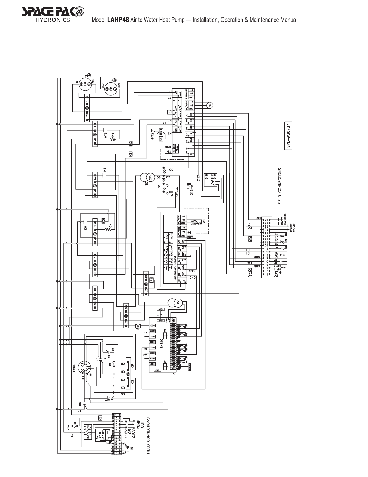
for the immersion heater. Refer to the Figures 9 and 10 of
this manual for detailed wiring.
LAHP Control Wiring Connection
The SpacePak LAHP requires a dry contact (relay) signal to
enable and select between heating and cooling modes. They
will not operate on the 24V signals from typical thermostats or air
handlers. Connecting 24V to either of these points will result in
erratic operation and may cause significant component damage.
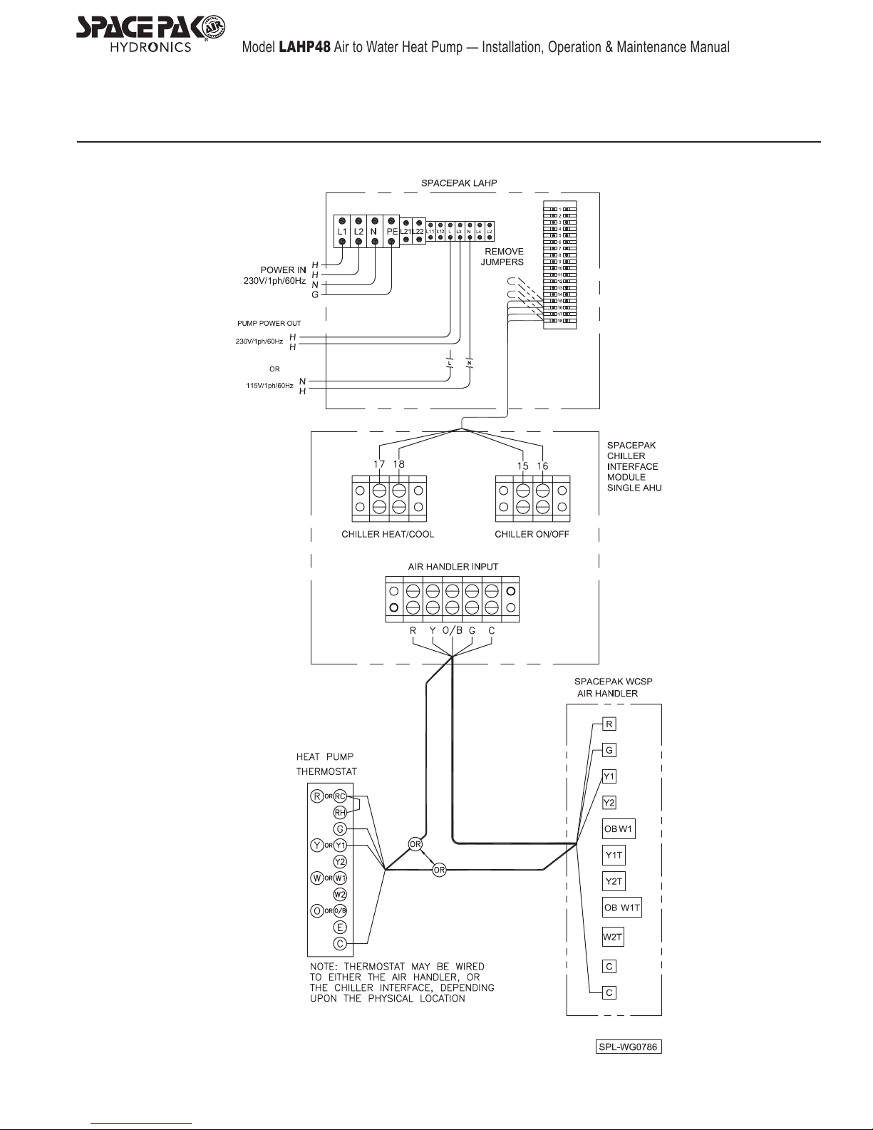
• Connect single zone systems to Heat Pump as shown in
Figure 9.
• Connect multiple zone system to Heat Pump using SpacePak
SSIC Control Module and instructions included with it.
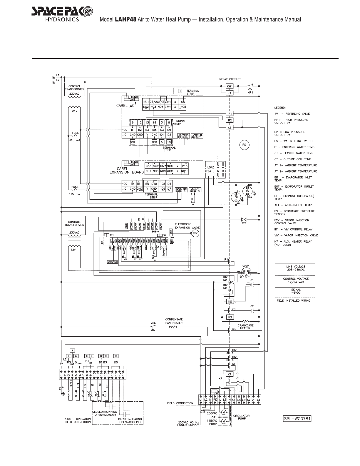
• See Figure 10, for chiller electrical ladder diagram. Section
8: Electrical Diagrams.
Figure 9 SpacePak Heat Pump field wiring — SINGLE air
handler
• Refer to manual supplied with SSIC Control Module for
connection and operational details.
Section 7: Start-up And Test
Preparing For Start-Up
1. With the heat pump isolated and dry, valves A & B closed,
charge the “system” (that is, all the plumbing not shown), and
remove as much air as possible through the air separator.
2. Apply a static pressure to the system, with all pumps off, of
15-25 PSI.
4. Crack the manual vent valve until you hear air escaping.
5. Allow the water to continue to fill the heat pump, displacing air.
This should go very slowly, and could take a minute or more.
6. When all the air has been displaced and a steady stream of
water is flowing out of the vent valve, fully open ball valve B.
7. Open ball valve A, a small amount of air might escape the
vent valve from the heat pump supply line.
8. When all the air has escaped, close the vent valve. Note:
this procedure fills the heat pumps in the opposite direction
of normal flow, so it must be done when all pumps are off.
– 9 –
Page 10

Model LAHP48 Air to Water Heat Pump — Installation, Operation & Maintenance Manual
Section 7: Start-up And Test (continued)
BEFORE Starting The Unit
Electrical shock hazard — Disconnect all
electrical power before proceeding with the
following. Verify that the system and all components
have been installed in accordance with this manual
and all applicable codes and instructions. Inspect
the SpacePak heat pump and all other system
components. All components should be in good
condition and operational. Inspect the water piping
for any signs of leakage.
Repair all system leaks. Leakage will cause pressure to drop,
preventing the heat pump from operating. Leaks also allow
introduction of excess make-up water, whether filled
automatically or manually. Check system pressure The pressure
should be at least 15 PSIG with heat pump/chiller not in
operation. Check all wiring connections to ensure terminal
connections are tight and all wiring is in place.
Start The SpacePak LAHP
Start In Cooling Mode
See the attached illustration; note this is not intended to include
all components in the system, just the minimum to properly
purge air from the chiller.
1. Apply power to the unit.
2. The display (Figure 1) should show the start sequence — uC2,
then 2.0, then the current water temperature. No other symbol
should appear.
3. When the display shows only temperature, lower the thermo-
stat setpoint below the current room temperature.
4. This begins a call for cooling, and the pump symbol will begin
to flash.
5. After 1 to 2 minutes, the pump symbol will change to constant
display, and the pump will begin circulating.
6. Assuming the water is outside of the cooling temperature
range (above 42°) the refrigeration system will initiate and
the numeral 1 will begin flashing.
7. After 1 to 2 minutes, the 1, or 3, or both numerals will change
to constant, the compressor symbol will turn on and one or
both compressors will start.
8. Observe for any alarms, errors, or faulty operation (noises,
vibration, etc.).
9. When operation is deemed satisfactory, raise the thermostat
set-point or turn it off.
10. The pump will run for approximately two minutes after the
compressor shutdown.
Start In Heating Mode
1. When the pump has stopped, change the thermostat to
Heating (if applicable) and raise the set point above current
room temperature.
2. This initiates a call in heating mode. The pump symbol will
begin flashing.
3. After 1 to 2 minutes, the pump symbol will change to constant
display, and the pump will begin circulating.
4. Assuming the water is outside of the heating temperature
range (below 1200F) the refrigeration system will initiate and
the 1, or 3, or both numerals will begin flashing.
5. After 1 to 2 minutes, the 1, or 3, or both numerals will change
to constant, the compressor symbol will turn on and one or
both compressors will start.
6. Observe for any alarms, errors, or faulty operation (noises,
vibration, etc).
Anti-freeze Cycle
Should the water temperature drop to 34°F during periods of nonuse, the pump will start and the anti-freeze heater (if connected)
will energize and continue to operate until the temperature
reaches 38°F.
If the water temperature continues to fall and reaches 33°F, the
Alarm symbol and Fault Code AL will be displayed, and the unit
will automatically start in heating mode. It will continue to run
until the water temperature reaches 38°F.
This provides the maximum level of protection in
all cases, but may use energy unnecessarily when
a suitable concentration of glycol anti-freeze
is installed. When freeze protection is sufficient,
these values can be adjusted to lower temperatures. Contact technical support for guidance in
reconfiguring these parameters, however it must be
understood that the installer is responsible for
ensuring sufficient freeze protection to the lowest
temperature allowed.
24-Hour Follow-up
Approximately 24 hours after start-up and testing, return to the
installation to verify proper operation. Perform the following
checks.
• Check system pressure. Add additional glycol/water mixture
if needed to restore pressure. (Pressure can drop as air is
removed from the system by the air vents.)
• Sample the glycol/water mixture in the system. Verify inhibitor
and glycol levels. Inspect the piping and components to
ensure there are no leaks. Repair any leaks immediately.
• Close the isolation valves on either side of the y-strainer at
the SpacePak heat pump return connection. Remove the
screen and inspect for sediment. Clean if necessary.
• If the strainer has become clogged with sediment, determine
whether the system needs to be drained, cleaned and
re-filled. Excessive sediment accumulation in the strainer will
reduce flow and cause the unit to shut down.
• Cycle the system on heating and cooling. Verify that all
components operate correctly.
– 10 –
Page 11
Model LAHP48 Air to Water Heat Pump — Installation, Operation & Maintenance Manual
Figure 9 Field Connections
Section 8: Electrical Diagrams
– 11 –
Page 12
Model LAHP48 Air to Water Heat Pump — Installation, Operation & Maintenance Manual
Section 8: Electrical Diagrams (continued)
Figure 10 SpacePak LAHP - Pictorial Wiring Diagram
– 12 –
Page 13
Model LAHP48 Air to Water Heat Pump — Installation, Operation & Maintenance Manual
Section 8: Electrical Diagrams (continued)
Figure 11 SpacePak LAHP Electrical Ladder Diagram
– 13 –
Page 14
Model LAHP48 Air to Water Heat Pump — Installation, Operation & Maintenance Manual
Section 9: Troubleshooting / Fault Codes
Figure 12 Troubleshooting Suggestions
Condition Possible Causes Verification Solution
Incorrect power supply Check power supply Supply correct power
Unit will not start
Compressor running - insufcient
cooling/ heating
High compressor discharge pressure
in cooling
High compressor discharge pressure
in heating
Low compressor suction pressure
in cooling
Compressor will not run
Noisy compressor
Fan will not run
Compressor runs - no heating/cooling
Low outlet glycol/water temperature in
cooling
Loose or broken wires Check wiring
Circuit breaker interrupted Check for short
insufcient pipe insulation Check insulation Add/repair insulation
Dirty coil Check coil Clean Coil
Low water ow
Dirty coil Check coil Clean Coil
Low water ow
Insufcient / no water ow Look for alarm symbol and FL fault code
Cooling operation in low ambient
Power supply failure Supply correct power
Failed compressor contactor Replace contactor
Loose power cable Check power cable Tighten power cable
Incorrect return water temperature setting Check return water temperature setting Adjust return water temperature setting
Low glycol/water ow Look for alarm symbol and FL fault code
Liquid returning to compressor
Compressor failure
Fan relay failure Replace fan relay
Fan motor failure Replace fan motor
No refrigerant charge Check for leaks Add appropriate refrigerant
Damaged heat exchange
Compressor failure Replace compressor
Improper temperature control setting
No load/rapid temperature drop
Look for alarm symbol and FL fault code
Measure water ow through heat
exchanger
Confirm outdoor ambient is lower
than typical for cooling operation, i.e.
<550F
Check for glycol/water leaks and/or
refrigerant leaks
Check cooling temperature setpoint and
differential
Ensure compressors are allowed to
run a minimum of three minutes before
reaching desired temperature
Repair or replace wiring
Clean strainer screen
Clear blockage
Remove air in piping
Verify operation/condition of water pump
Flow should be a minimum of 8 GPM
Clean strainer screen
Clear blockage
Remove air in piping
Verify operation/condition of water pump
If low ambient cooling is desired, contact
Technical Support for procedure to modify
fan operating parameters.
Clean strainer screen
Clear blockage
Remove air in piping
Replace compressor
Replace heat exchanger
Contact Technical Support for instructions
to reset cooling setpoints
Verify cooling function when there is
sufcient heat load to allow continuous
operation.
– 14 –
Page 15
Model LAHP48 Air to Water Heat Pump — Installation, Operation & Maintenance Manual
Section 9: Troubleshooting / Fault Codes (continued)
Figure 13 Fault Codes
FAULT
CODE
E1 Water Inlet Temperature Sensor Failure Short Circuit or Sensor Open Check/Replace Sensor
E2 Water Outlet Temperature Sensor Failure Short Circuit or Sensor Open Check/Replace Sensor
E3 Outside Coil Temperature Sensor Failure Short Circuit or Sensor Open Check/Replace Sensor
E4 Refrigerant Discharge Pressure Sensor Failure Short Circuit or Sensor Open Check/Replace Sensor
E8 Outdoor Ambient Temperature Sensor Failure Short Circuit or Sensor Open Check/Replace Sensor
AL Anti-Freeze Cycle Error / Cooling Water Temperature has Fallen Below
FL Flow Switch Error Inadequate Water Flow Rate Verify or Increase Glycol Concentration and Contact SpacePak
HP1 High Pressure Alarm
LP1 Low Pressure Alarm
MALFUNCTION REASON ACTION
Check Flow Rate
System1
System1
Antifreeze Protection Setpoint
Discharge Pressure Exceeds Maximum
Allowable
Suction Pressure Below
Minimum Allowable
Check For Blockage in Piping
Technical Support for Instructions to Lower Alarm Setpoint
Cooling Mode:
Check for Dirty Coil
Check for Restricted Air Flow
Check for Excessive Ambient Temperature
Heating Mode:
Check for Sufcient Water Flow Rate
Cooling Mode:
Check for Sufcient Water Flow Rate
Heating Mode:
Check for Dirty Coil
Check for Restricted Air Flow
Check for Low Ambient Temperature
– 15 –
Page 16
Model LAHP48 Air to Water Heat Pump — Installation, Operation & Maintenance Manual
Section 10: Annual Maintenance
Perform Annual Inspection
Check Glycol/Water Mixture
1. At least once annually, sample the system fluid to verify that
the glycol concentrations meet the minimum value given in
Figure 7, page 7. Also test the inhibitor concentration. Add
glycol and inhibitor as needed to return the system to the
correct concentrations.
2. Perform any and all other tests as recommended by the anti-
freeze manufacturer’s instructions in order to ensure optimal
performance and maintain warranty protection on all installed
components.
Check Operating Pressure
1. Check the glycol/water system pressure. Operating pressure
should be between 15 and 25 PSIG. Adjust fluid volume if
needed to restore pressure.
2. If pressure is low, check system for evidence of leaks. Repair
all leaks immediately. Perform annual inspection
Electrical shock hazard — Disconnect all electrical
power before proceeding with the following.
Inspection of System
At least once annually, perform a complete inspection of the
system, including at least the following:
• Inspect the LAHP for signs of dirt or debris accumulation.
Remove any debris and notify the building owner that the
unit must be kept clean and unobstructed.
• Inspect glycol/water system piping and components.
Repair or replace any defective components. Repair all
leaks immediately.
• Close the isolation valves on either side of the y-strainer
at the SpacePak heat pump return connection. Remove
the screen and inspect for sediment. Clean if necessary.
NOTE: If the strainer has become clogged with sediment,
determine whether the system needs to be drained,
cleaned and re-filled. Excessive sediment accumulation
in the strainer will reduce flow and cause the unit to shut
down.
• Inspect all wiring and wiring connections. Tighten
connections if needed. Correct any problems found.
• Check the fuses or breakers to ensure they are correctly
sized and properly installed.
• Clean the LAHP heat exchangers and air openings.
• Cycle the system on heating and cooling. Verify that all
components operate correctly.
Preparing The LAHP For Shut Down
DO NOT turn off power to the LAHP in the winter or any time
when there is a possibility of freezing. Power must be ON for the
automatic anti-freeze operation to occur. See information below
for preparing the unit for shut down.
1. When the water temperature drops below 34°F during periods
of non-use, the pump will start and the anti-freeze heater
(optional, when installed) will energize and continue to operate
until the temperature reaches 38°F.
2. If the LAHP must be turned off or left idle during periods when
freezing is possible, one of the following must be done:
a. Verify that sufficient glycol solution is present to protect
against most extreme anticipate conditions
b. — OR — Drain heat pump and external piping completely.
To restart after shutdown
1. If unit was drained, refill.
2. Follow start up procedure on page 9 Section 7.
– 16 –
Page 17
Model LAHP48 Air to Water Heat Pump — Installation, Operation & Maintenance Manual
Section 11: Replacement Parts
Figure 16 Replacement Parts LAHP48
Item Part Number Description
1 45R2000-3138 Carel Controller MCH20000011
2 45R20000-370007 Transformer 41x26.5F
3 45R2000-3223 Sensor 150-503-96115 (50K)
4 45R20000-430031 System Protection Module MXL033
5 45R2000-3220 Sensor 150-502-98674 (5K)
6 45R20000-350004 Compressor Capacitor CBB65-80μF/450V
7 45R2000-3524 Compressor Capacitor CBB65A-98μF/300VAC
8 45R20000-360035 Start Relay HLR3800-4AH3D
9 45R2001-3630 Intermediate Relay JQX-13F A240-2Z1(555)
10 45R20000-360007 Single Phase AC Contactor HCC-2XU04NN
11 45R2000-3214 Compressor Cable Heater 40W
12 45R2000-3619 Relay HF105F-4
13 45R2000-3215 Bottom Plate Cable Heater 70W
14 45R2001-3674 Mechanical Thermostat GWL-30190
15 45R2000-3635 Timer Relay DAA51CM24
16 45R20000-430048 DC Motor Module MXL048
17 45R2000-3136 Fan Motor On/Off Control Carel CONVONOFF0
18 45R2000-3202 Sensor 150-502-98674 (5K) XH-2Y
19 45R20000-120100 Plate Heat Exchanger B8THx14/1P-NC-M
20 45R20000-140027 Filter
21 45R20000-140194 Electronic 2-Way Valve FDF6MG-3/8 1005
22 45R20000-140234 Electronic Expansion Valve UKV-18D203
23 45R20000-360059 Pressure Switch 3.2MPa/4.0MPa
24 45R20000-360082 Pressure Switch 0.1MPa Off / 0.2MPa On
25 45R2001-1491 4-Way Valve
26 45R2001-1497 Check Valve CV-8
27 45R2001-3605 High Pressure Switch 3.2MPa / 4.4MPa
28 45R2002-1494 Thermal Expansion Valve BAE4-1/2ZW195
29 45R20000-330110 Fan Motor FN045-6EH.2F.V7P3
30 45R35019-120011 Condensor Coil
31 45R35019-120008 Plate Heat Exchanger B25THx36/1P-SC-M
32 45R20000-120029 High Pressure Storage Tank 0150700052-M\
33 45R3500-1401 Liquid Gas Separator MA013008A
34 45R2000-3606 Water Flow Switch HF68P/1"NPT
35 45W55-WG0784 Compressor ZHI14K1P-PFV-526
– 17 –
Page 18
Model LAHP48 Air to Water Heat Pump — Installation, Operation & Maintenance Manual
Section 12: Limited Warranty
LIMITED WARRANTY
Air to Water Reverse Cycle Heat Pump
The “Manufacturer” warrants to the original owner at the original installation site that the Air to Water
Reverse Cycle Heat Pump (the “Product”) will be free from defects in material or workmanship for a
period not to exceed one (1) year (parts) or two (2) years (compressor) from the startup. If upon
examination by the Manufacturer the Product is shown to have a defect in material or workmanship
during the warranty period, the Manufacturer will repair or replace, at its option, that
which is shown to be defective.
This limited warranty does not apply:
a) If the Product has been subjected to misuse or neglect, has been accidentally or intentionally
damaged, has not been installed, maintained or operated in accordance
written instructions, or has been altered or modi
b) To any expenses, including labor or material, incurred during removal or reinstallation of the
defective Product or parts thereof.
c) To any workmanship of the installer of the Product.
This limited warranty is conditional upon:
a) Shipment, to the Manufacturer, of that part of the Product thought to be defective. Goods can
only be returned with prior written approval from the Manufacturer. All returns must
prepaid.
b) Determination, in the reasonable opinion of the Manufacturer, that there exists a defect in
material or workmanship.
ed in any way.
part of the Product
with the furnished
be freight
Repair or replacement of any part under this Limited Warranty shall not extend the duration of the
warranty with respect to such repaired or replaced part beyond the stated warranty period.
THIS LIMITED WARRANTY IS IN LIEU OF ALL OTHER WARRANTIES, EITHER EXPRESS OR
IMPLIED, AND ALL SUCH OTHER WARRANTIES, INCLUDING WITHOUT LIMITATION IMPLIED
WARRANTIES OF MERCHANTABILITY OR FITNESS FOR A PARTICULAR PURPOSE, ARE
HEREBY DISCLAIMED AND EXCLUDED FROM THIS LIMITED WARRANTY. IN NO EVENT
SHALL THE MANUFACTURER BE LIABLE IN ANY WAY FOR ANY CONSEQUENTIAL, SPECIAL, OR
INCIDENTAL DAMAGES OF ANY NATURE WHATSOEVER, OR FOR ANY AMOUNTS IN EXCESS
OF THE SELLING PRICE OF THE PRODUCT OR ANY PARTS THEREOF FOUND TO BE
DEFECTIVE. THIS LIMITED WARRANTY GIVES THE ORIGINAL OWNER OF THE PRODUCT
SPECIFIC LEGAL RIGHTS. YOU MAY ALSO HAVE OTHER RIGHTS WHICH MAY VARY BY EACH
JURISDICTION.
– 18 –
Page 19
Model LAHP48 Air to Water Heat Pump — Installation, Operation & Maintenance Manual
– 19 –
Page 20

IN UNITED STATES: 260 NORTH ELM ST. WESTFIELD, MA 01085 800-465-8558 / FAX (413) 564-5815
IN CANADA: 7555 TRANMERE DRIVE, MISSISSAUGA, ONTARIO, L5S 1L4 (905) 670-5888 / FAX (905) 670-5782
 Loading...