

Page 1
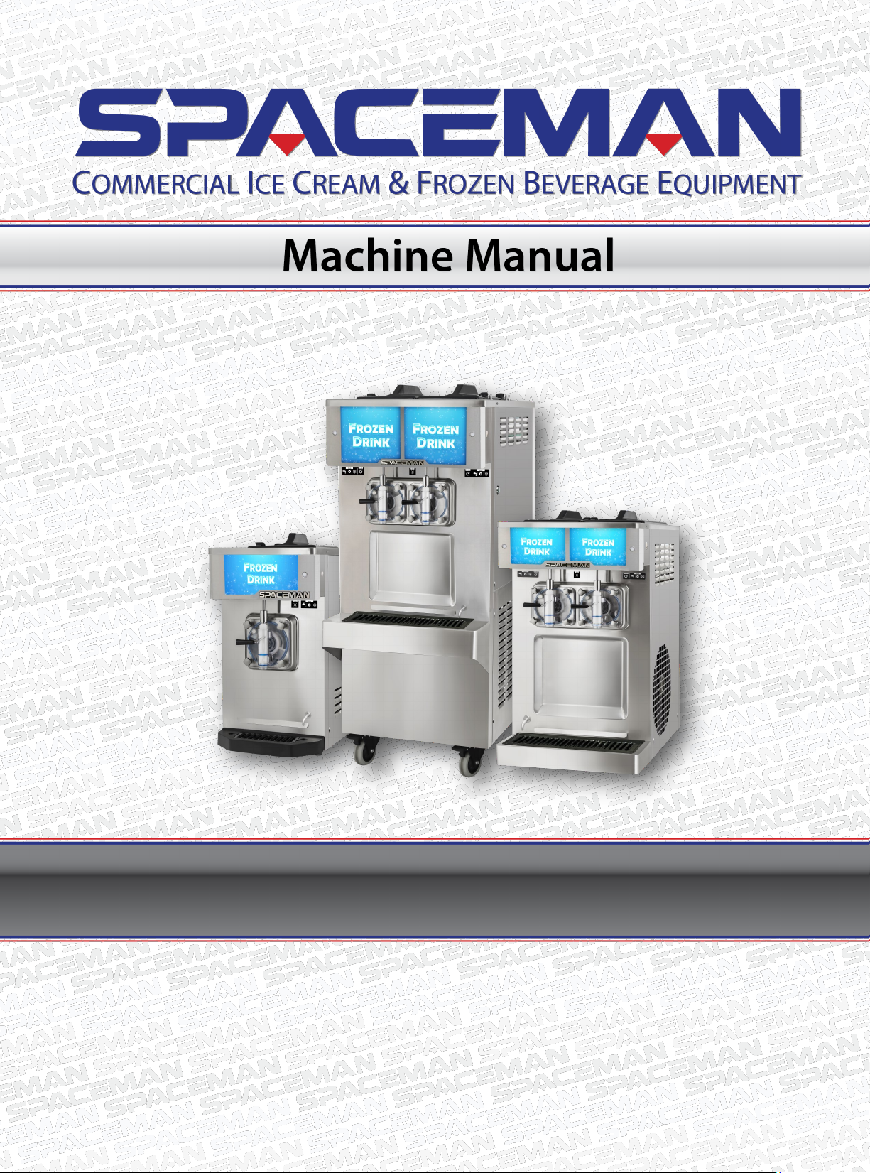
Counter or Floor Standing
Page 2
........................................................................................................................
.................................................................................................................
.....................................................................................................
.............................................................................................................
...................................................................................................................
..........................................................................................
Disassemble Parts .......................................................................................................................... 6
Wash And Sanize Parts ................................................................................................................ 7
Assemble Parts ............................................................................................................................... 8
Sanize ......................................................................................................................................... 10
.......................................................................................................................
Introducon ................................................................................................................................. 11
Add Product to Machine .............................................................................................................. 11
Freeze Product ............................................................................................................................ 11
Dispense Product ........................................................................................................................ 12
Status Light .................................................................................................................................. 12
Wash ............................................................................................................................................ 12
Standby ........................................................................................................................................ 12
Low Mix Alarm ............................................................................................................................. 12
Light Box ....................................................................................................................................... 12
Spinner ......................................................................................................................................... 13
Adjust Product Consistency ......................................................................................................... 13
Machine Power Reset .................................................................................................................. 13
........................................................................................................................
This machine has many built-in safety features to protect the operator while the machine is
running.
All personnel operang this machine read and understand this manual in its enrety. Failure to
comply with this manual may damage the machine and cause severe injury to the operator.
Denotes an acon that WILL cause
harm to the operator or machine if performed
incorrectly.
Informs the operator of a task that
may lead to harm if protocol is not properly
performed.
Represents a vital mechanical step
or note that the user must be aware of.
Non-hazard, but pay extra aenon.
Welcome to your Spaceman frozen beverage machine, engineered and designed to provide dependable
operaon and a consistent quality product. Your machine is approved for dairy and nondairy products, with
hopper refrigeraon funcon to maintain product temperature below 4oC (40oF), and with more automated
analog control system for operaonal ease and eciency . All models, countertop or oor, single or two avor,
operate in the same fashion.
This manual is a universal version that provides instrucons on installaon, operaon, cleaning and roune
maintenance. Informaon contained in this manual may be subject to change. Please check online or contact
your local Spaceman distributor for connued updates and detailed informaon about your Spaceman machine.
Page 3
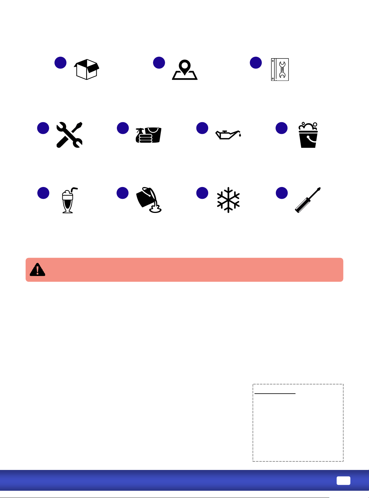
Unpack and inspect machine,
parts, and accessories.
Place machine in appropriate
food preparaon area. Comply
with all installaon requirements.
Read and understand
ALL safety and standard
operang procedures.
Fully disassemble machine,
and prepare parts for
cleaning.
Thoroughly clean and scrub
machine hoppers, cylinders,
and all parts.
Lubricate and re-assemble
all machine parts.
Prepare product in a separate
container, and ensure product
is thoroughly mixed.
Add product to hoppers
and prime the cylinder
using the prime plug.
Turn machine to FREEZE
mode, and wait for product
to reach frozen consistency.
Slightly adjust viscosity
seng as necessary to
adjust product rmness.
Inspect the machine for any shipping damage. If you nd any, contact Spaceman Technical Service immediately
aer unpallezing. Our technicians will help you assess the damage and determine the appropriate acon prior
to accepng the delivery.
1. Cut packing straps, and remove cardboard lid and outer sides from the pallet. DO NOT cut cardboard.
2. Remove plasc wrapping around machine.
3. Cut stabilizing straps, being careful not to scratch or dent the machine panels.
4. Prepare the area where the machine will be placed, remove packing cardboard from underneath machine,
and place ramp wedges near front casters.
5. Unlock front casters, and roll machine down the wedges o the pallet.
6. Place the machine in its nal locaon according to the Installaon Requirements.
: Unpallezing requires liing.
Failure to do so may result in severe injury or damage.
Inspect equipment for hidden damage before signing for delivery.
Refer to the detailed parts diagrams on the back pages if necessary.
1. Remove all packaged parts and accessories from your machine.
2. Organize items on a clean table or operang area using the checklist.
3. Inspect for damage immediately upon unpacking and call Spaceman
Technical Service if you discover any damaged or missing parts.
4. Clean and properly lubricate machine parts prior to machine operaon.
Included Parts:
• Hopper Cover (1 or 2)
• Front Drip Tray + Splash Shield
• Dispensing Handles
• Start-Up Kit
• Operator’s Manual
• Cleaning Guide
• Quick Operaon Guide
Fully sanize
machine.
Page 4
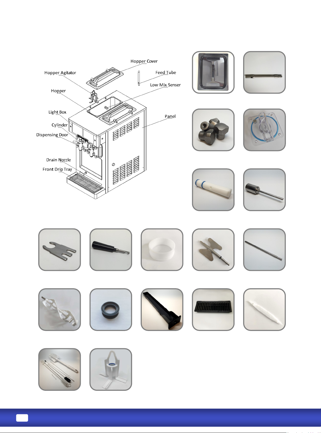
Torque Arm
Dispensing Door with
Prime Plug, and Gasket
Draw Valve
with O-Rings
Ice Buster
Draw Valve Pin
Draw Handle
Beater
Feed Tube
Beater Guide
Door Hand Screws
End of Seal
Brush Kit
(Oponal)
Internal Drip Tray O-Ring Removal Tool
Hopper Cover
Hopper Agitator
(Oponal)
Front Drip Tray
with Splash Shield
The image displayed is for illustraon purpose only and may
dier from the actual product.
Torque Assembly
with O-Ring
Page 5
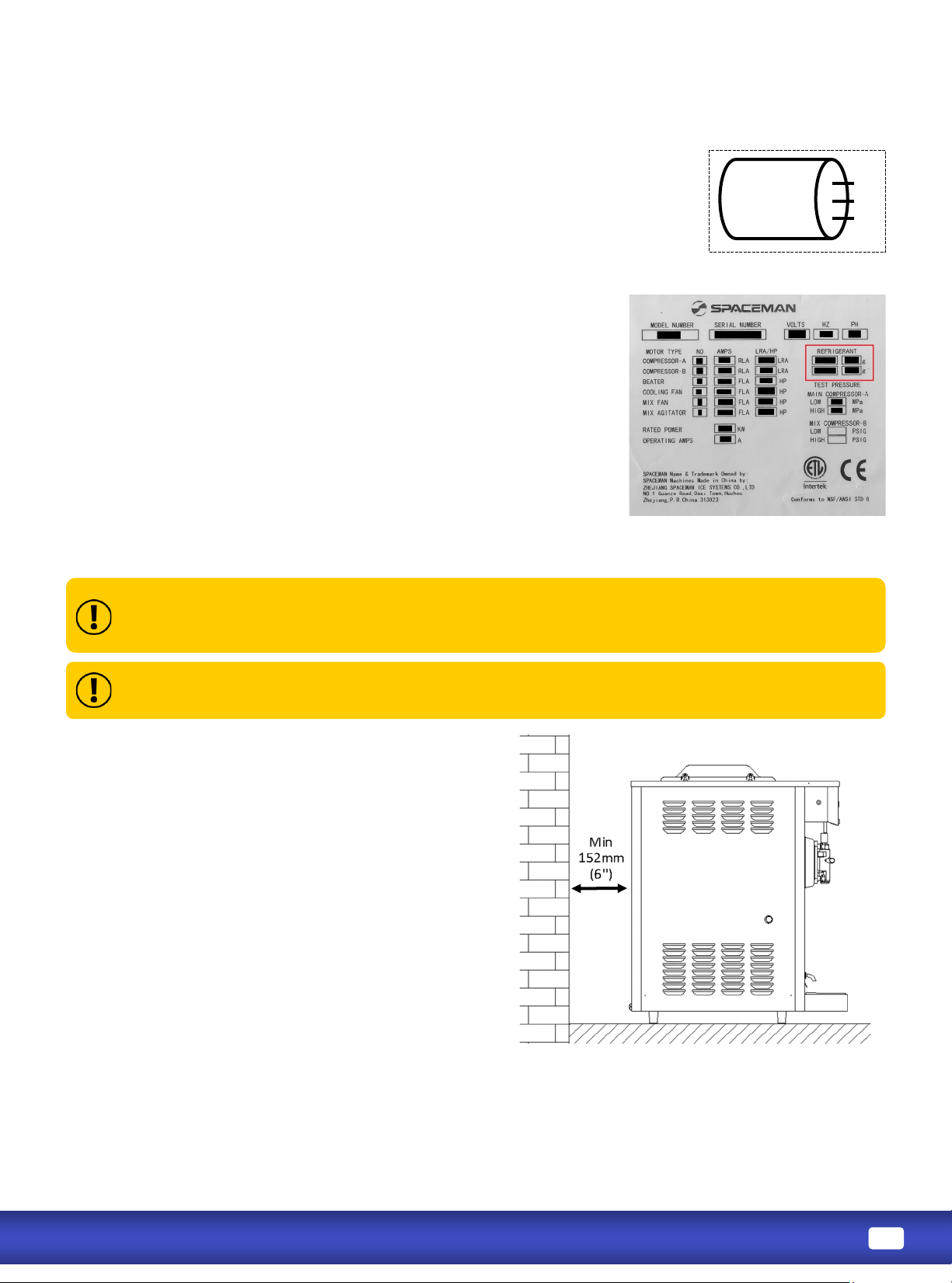
Spaceman requires that only the specied refrigerant be used
in your machine.
Alternave refrigerants may cause damage to the cooling
system and/or prevent the machine from operang at opmal
performance.
If you require an alternave refrigerant, please call Spaceman
Technical Support for a list of compable alternaves for your
compressor.
• Place on a at, level, and solid surface ed to
the machine dimensions
• Ensure a minimum 152mm (6'') clearance on
the exhaust side (Side or Back)
• Completely clear area of dust, grease, and
airborne parcles
• Place away from hot equipment such as stoves,
frying baskets, ovens, etc.
Failure to comply will damage the machine and refrigeraon components and will void all
warranes.
Operang in higher ambient temperatures will result in degraded performance.
1. Connect all wires to Circuit Breaker (including neutral & ground bus
terminals) or Local Plug according to supply voltage and wire codes on
machine power cable.
2. Verify Incoming Supply Cable is wired the same way on Circuit Breaker or
Wall Receptacle before switching on or plugging in the machine.
The image displayed is for illustraon purpose only and may
dier from the actual product.
Page 6
• Daily
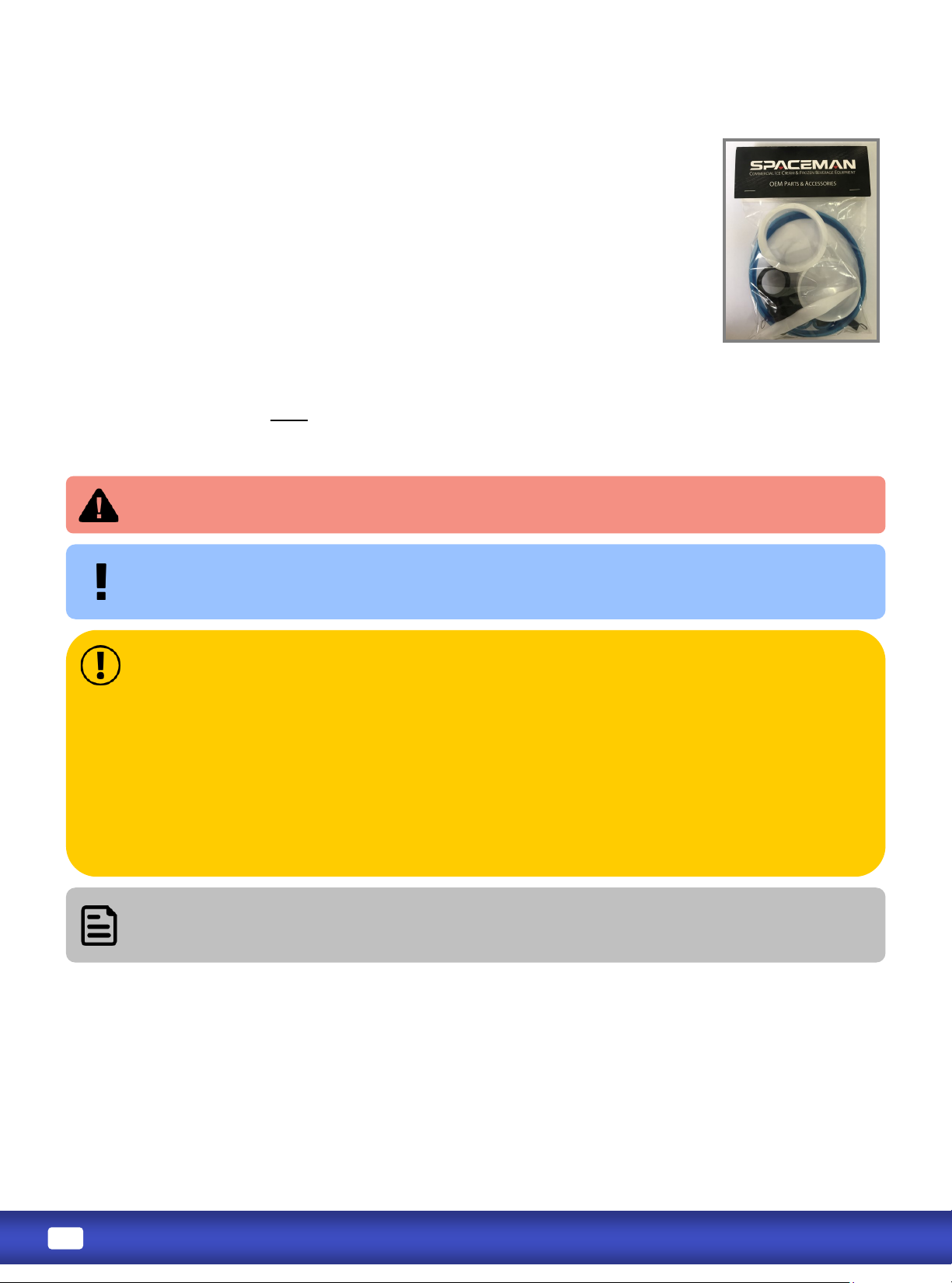
•: Every 1 to 3 months*
• Quarterly**
* Based on machine usage and cleaning intervals; a Tune-Up Kit is available with all
wearable parts (O-rings, gaskets, etc.) except scraper blades
** Based on cleanliness of locaon and proximity to powder-based machines.
Preventave maintenance includes cleaning condensers, checking belt tensions, and
cleaning the interior of the machine frame as required.
For opmal machine performance and many years of eciency and reliability
from your machine, Spaceman recommends cleaning and sanizing the
machine and its parts .
Cleaning and sanizing schedules are governed by state or local regulatory agencies
and MUST be followed accordingly.
• Do NOT run the machine without properly lubricang required parts
• Do NOT clean the machine with abrasive or toxic chemicals and cleaners. Doing so may cause
damage to the stainless steel material
• ONLY use Spaceman-included cleaning brushes and lubricaon
• NEVER use metal objects to clean or operate the machine
• ALWAYS replace wearable parts a minimum of every 3 months
• ALWAYS prime machine prior to operang
• ALWAYS inspect parts for excess wear and damage
Addional brushes, lubricaon, wearable parts, and tools can be purchased from Spaceman
to ensure proper maintenance. Extra wearable parts are found in the Start-Up Kit.
If this is the rst me operang the machine, you MUST clean and sanize ALL parts
prior to running the machine.
The image displayed is for illustraon
purpose only and may dier from the
actual product.
-
Page 7
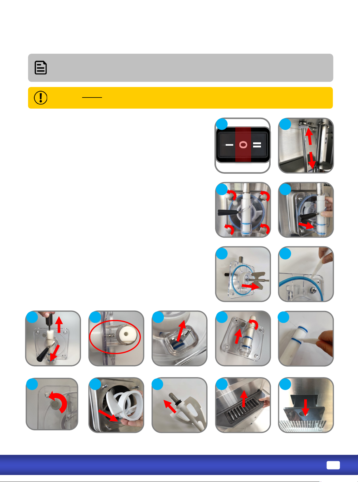
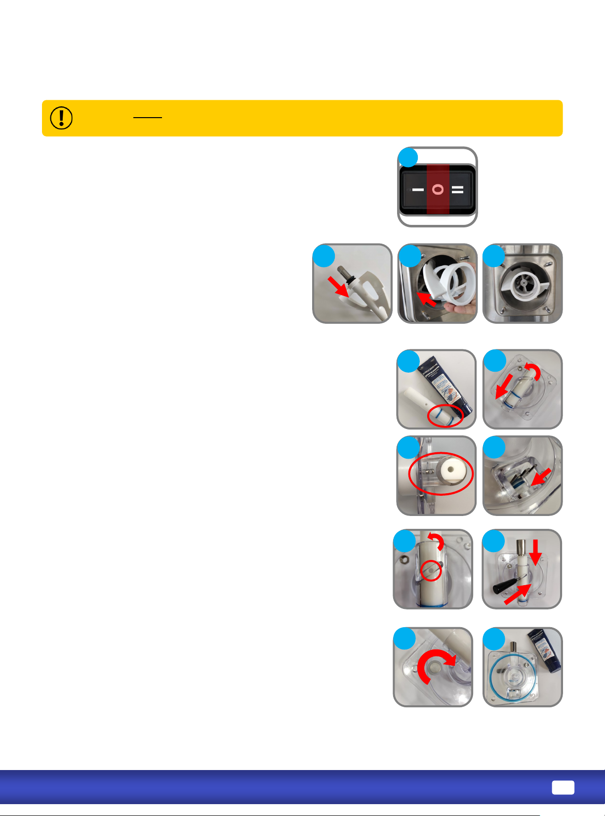
1. Verify the power switch is turned to OFF.
2. Remove the torque arm, rst pulling up out of the torque
assembly and then down out of the at sensor arm.
3. Remove dispensing door hand-screws.
4. Remove dispensing door assembly.
5. Remove torque assembly and remove O-ring from torque
assembly using O-ring removal tool.
6. Remove dispensing door gasket using O-ring tool.
7. Rotate draw valve unl the at part at the top is perpen-
dicular to the clear face of the dispensing door (use towel
if necessary).
8. Remove ice buster.
9. Remove draw valve, twisng it while removing.
10. Remove draw valve O-rings using O-ring tool.
11. Unscrew and remove prime plug from dispensing door.
12. Remove beater assembly.
13. Remove end of seal from beater assembly.
14. Remove front drip tray and internal drip tray.
Prepare dishwashing area prior to disassembly, and use a bucket to temporarily store
removed parts.
Always separate O-rings and gaskets from metal parts to prevent damage while
washing.
Page 8
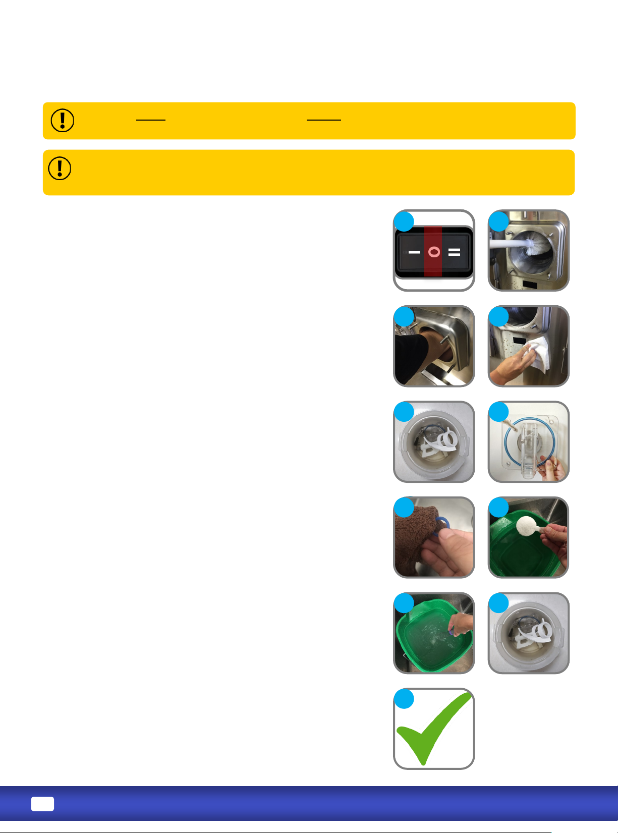
1. Verify power switch is turned to OFF.
2. Use the large brush and cool water to thoroughly clean
inside the cylinder; be sure to scrub the back of the
cylinder and verify the cylinder is free of ALL product.
3. Thoroughly clean and dry the rear of the cylinder with
the rushes and a clean, dry towel.
4. Gently clean and wipe down the outside of the
machine.
5. Carefully and thoroughly wash all parts removed from
the machine using brushes, sponges, and clean towels;
when cleaning the dispensing door, clean the priming
port with a small brush.
6. When cleaning the dispensing door assembly, clean
the priming ports with a small brush.
7. Carefully and thoroughly clean all gaskets and
O-rings removed from the machine; be sure to wipe
gaskets and O-rings to remove excess lubricant.
8. Mix a minimum of 7.57 liters (2 gallons) of food-grade
sanizer in a bucket or container for each hopper.
9. Soak all parts in the sanizer soluon for 10 minutes.
10.Verify all parts are clean and sanized prior to reassembling the machine.
Never wash parts in a dishwasher. Always hand-wash components with nontoxic,
food-safe cleaners.
se Sanizer mixed to 100PPM Chlorine with an acve ingredient of Sodium Dichloro-S-
Triazinetrione Dihydrate. If warm water is required to dissolve sanizer, allow the soluon me to
cool before adding to machine.
Page 9
Never force the installaon of any parts. All parts t correctly without force. If parts
don’t seem to t, remove all parts and repeat assembly.
a. Lubricate the seal on both ends; then place
seal on the beater.
b. Insert beater assembly into cylinder, making
sure beater stay in place; turn assembly unl
they engage the beater sha key and no
longer turn 360°
a. Place O-rings on draw valve, coang with Spaceman lubri-
cant.
b. Insert draw valve 7/8 way into the dispensing door from
the top, rotang as you install.
c. Turn draw valve so the at poron at the valve top is
perpendicular to the clear face of the dispensing door.
d. Insert ice buster through the dispensing spout at the
boom of the door and into the slot on the draw valve.
e. Rotate draw valve to lock ice buster in place; turn valve
unl the hole for the draw handle is accessible on front.
f. Insert draw handle; secure in place with valve pin.
g. Screw prime plug onto dispensing door.
h. Place dispensing door gasket on door, coang with
Spaceman lubricant
Page 10
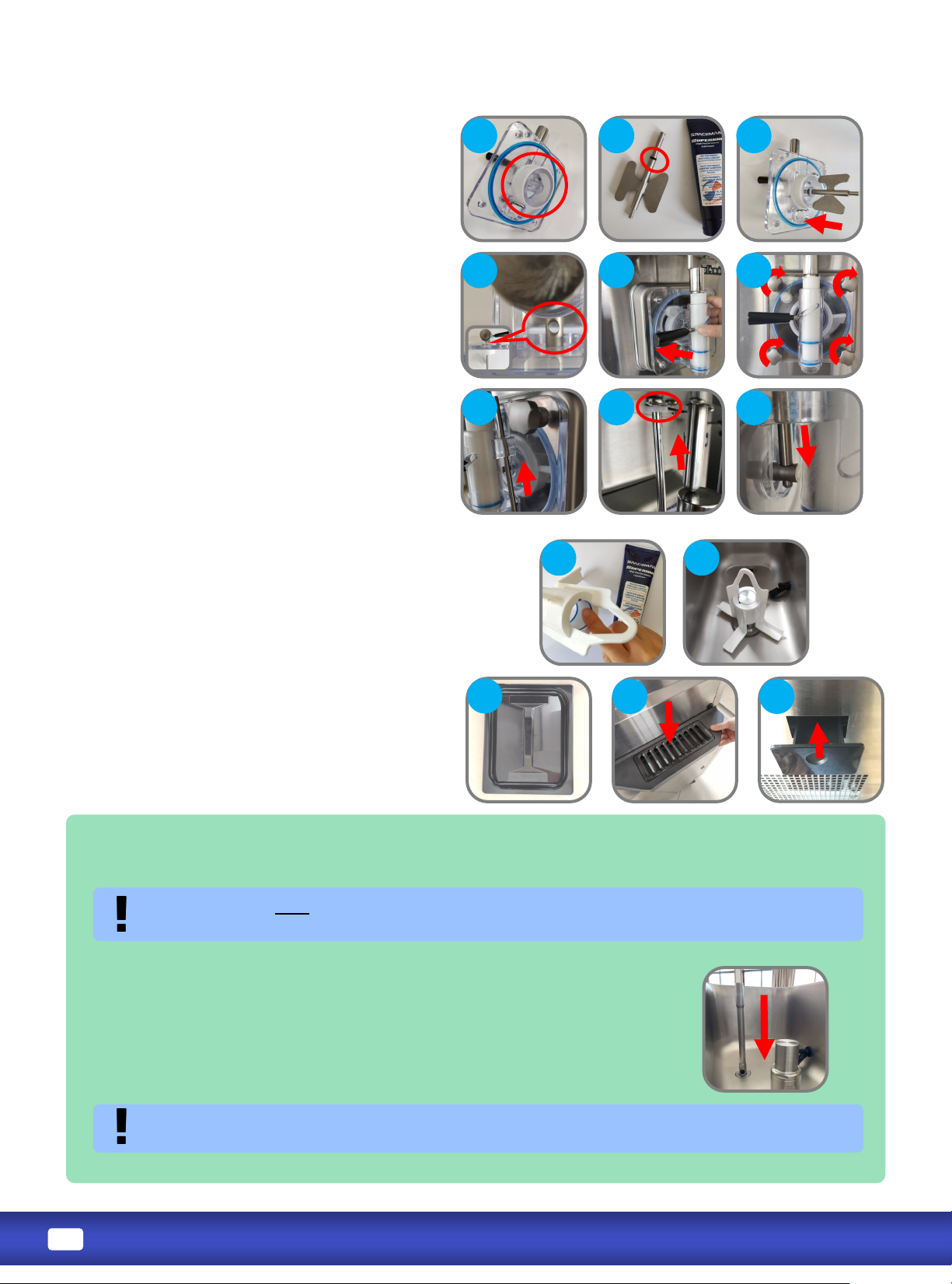
i. Place beater guide onto dispensing
door, with ange ush with the back of
the door.
j. Place O-rings on torque assembly; coat
all ring areas with Spaceman lubricant.
k. Install torque assembly onto
dispensing door. Rotate torque
assembly so the hole for the torque
arm is vercal, facing up and down.
l. Install dispensing door assembly.
m. Tighten dispensing door hand-screws
in a cross-paern.
n. With tapered end down, install torque
arm up through the sensor pin hole
under the overhead and then down
into the torque assembly; torque arm
should move freely back and forth.
a. If machine has hopper agitator,
lubricate inside it and install with arrow
poinng up.
b. Install hopper cover and drip trays
(internal and front).
The air tube is required to be used when making shakes, milkshakes, and some smoothies.
• Aer Purging and Priming the freezing cylinder, install the air tube
into the hopper with the product inlet hole at the boom.
• Once the air tube is installed, connue to the instrucons to Freeze
Product.
It is recommended to be used with slushies, margaritas, daiquiris, or other
non-dairy products.
The air tube should be cleaned daily.
Page 11
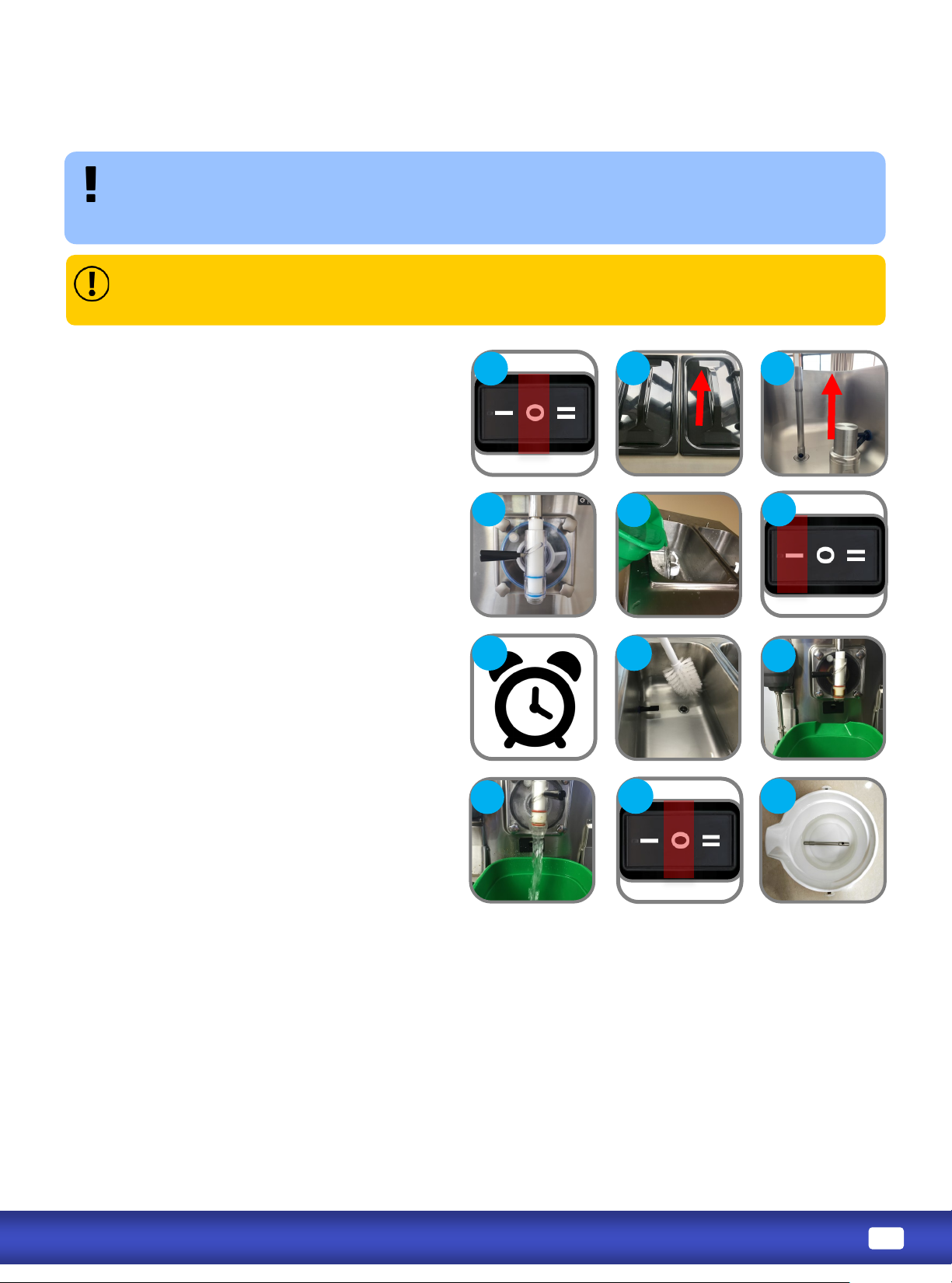
Aer sanizing the machine, DO NOT rinse or touch areas that have been sanized.
Product must be added immediately. If new product will not be added immediately, rinse machine
with clean water and loosen door hand-screws to allow cylinder to air-dry. Sanize machine before
using again.
1. Verify assembly is complete and machine
power is OFF.
2. Remove hopper cover and air tube.
3. Verify the draw valve is in the CLOSED
posion (LEFT).
4. Slowly pour 7.57 liters (2 gallons) of the
food-grade sanizer soluon into each
hopper, allowing it to ow into the
cylinder.
5. Turn power switch to WASH.
6. Allow soluon to agitate for 5 to 10
minutes; NEVER leave machine on WASH
for more than 10 minutes.
7. While agitang, gently use a clean brush to
scrub and distribute sanizer soluon
along hopper walls and hopper agitator (if
present).
8. Place a bucket or container below the
draw valve.
9. OPEN the draw valve (RIGHT) and drain
soluon from the machine.
10.Turn power switch to OFF.
11.Submerge air tube into sanizer soluon.
se Sanizer mixed to 100PPM Chlorine with an acve ingredient of Sodium Dichloro-S-
Triazinetrione Dihydrate. If warm water is required to dissolve sanizer, allow the soluon me to
cool before adding to machine.
Page 12
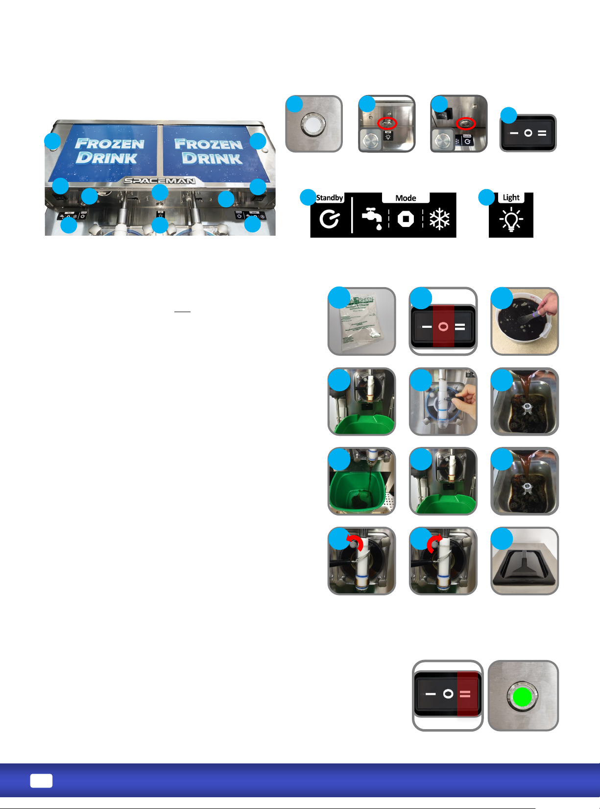
1. Verify machine has been recently sanized (within
1 hour); if machine has not been recently
sanized, verify door hand-screws are ght, and
perform sanizing steps (Page 10).
2. Turn power switch to OFF.
3. Thoroughly mix and prepare at least 7.57 liters (2
gallons) of product according to manufacturer
instrucons; mix should be cool and smooth (free
of large chunks).
4. Place a bucket or container below the draw valve.
5. OPEN draw handle (RIGHT).
6. Pour 2 liters (0.53 gallons) of product into the
hopper; sanizer will start to ow out of the draw
spout.
7. Once sanizer has been purged from the machine
and a steady stream of product is owing from the
spout, CLOSE draw handle (LEFT).
8. Pour remaining product into the hopper.
9. Open the prime screw (counter-clockwise) on the
front of the dispensing door and allow the cylinder
to ll with product to the desired level;
cylinder must be at least 75% full to operate.
10. Close the prime screw and ghten completely.
11. Replace hopper cover.
1. Verify cylinder is full of mixed product.
2. Turn power switch to FREEZE and verify STANDBY mode is o .
Light on front panel illuminates GREEN.
3. The motor will begin to agitate the product, and the cooling system will
begin to freeze the product.
4. Freezing product takes approximately 10 minutes; product is at the
adjusted viscosity when the at sensor arm is switched to the RIGHT.
5. When the product reaches the desired viscosity, it is ready to dispense.
Status Light
Power Switch
STANDBY WASH STOP FRREZE
Light Box Buon
(If present)
Standby Buon
Light
(If present)
Page 13
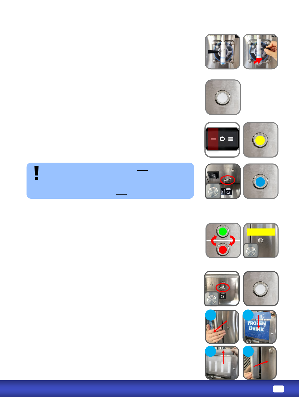
1. OPEN draw handle (RIGHT) unl the desired amount is dispensed.
2. CLOSE the draw handle (LEFT) when nished dispensing.
In STANDBY, product remains below 5oC (41oF) in both the
cylinder and hopper, but will NOT be frozen.
Press on STANDBY buon underneath overhead.
Status light illuminates BLUE.
Turn power switch to WASH. Status light illuminates YELLOW.
The motor will begin to agitate the product or water.
Press on Light Box buon underneath the overhead, front light
panel(s) and boom light strip will illuminate.
Beeper Reset
1. Pull boom of light panel assembly towards you then down to
take it o. Do not disconnect wires.
2. Push light panel in from the front. Insert Flavor Card in between
the light panel and the frame.
3. If Flavor Card is with adhesive on the back, push light panel in and
then up to take it out from the top. Sck Flavor Card on the light
panel, then insert the light panel in behind the frame from the top
down.
4. Insert top of the light box assembly into the downward lip of the
top panel of the machine. Push up while aligning the pin holes on
the boom le and right of the light box with the pins on the
overhead side panels. Push the boom in to lock in place .
RGB light that is located on the le or right side of front light box
panel. Light will turn solid GREEN, YELLOW or BLUE and may ash in
RED to indicate the corresponding operaon mode.
GREEN indicates FREEZE mode.
YELLOW indicates WASH mode.
BLUE indicates STANDBY mode.
Flashing RED and GREEN indicates LOW MIX alarm condion.
Mix low light is located on front panel of machine. Status light will
ash in RED and GREEN. The alarm beeper will go o when mix level
in hopper is low. Hopper should be relled as soon as possible.
Alarm beeper can be turned o by pressing the Beeper Reset buon
on side panel of the overhead.
Always maintain at least 2cm of mix in the hopper. If you neglect to
add mix, a freeze-up may occur. This will cause eventual damage to
the beater assembly, the dispensing door, and gear box.
Page 14
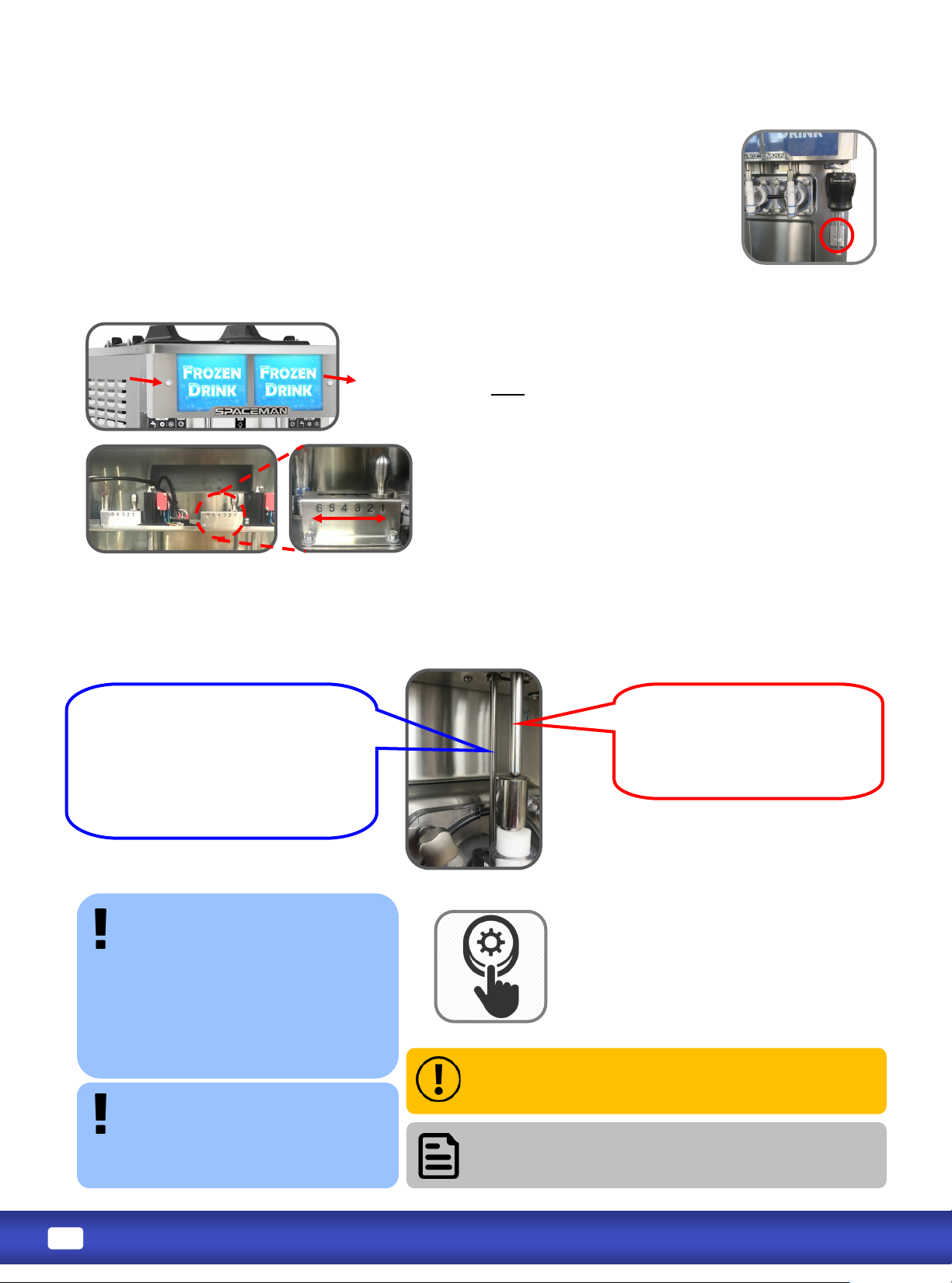
Located directly above the draw valve, this arm tells the machine when product is being dispensed
and how rm the product is. Beater and cooling systems are turned on and o based on
informaon from the sensor arms.
The viscosity adjustment, located behind the faceplate,
controls the rmness of dispensed product. The higher the
viscosity, the more rm the product. Viscosity sengs
should NOT need connuous adjustment.
Take o the faceplate. Viscosity is from Soer to Harder
from level 1 - 6. Make small adjustments each me, and
allow at least 10 to 15 minutes between adjustments to
evaluate product rmness.
Arm moves up and down and
tells machine when product is
being dispensed.
It moves UP when draw handle
is in the OPEN posion.
Flat arm moves le and right and
tells machine when product is at
desired consistency.
Switched RIGHT means consistency
is correct. Switched LEFT or IN THE
MIDDLE means consistency is not
yet correct.
If machine doesn’t turn on, turn power switch
OFF, wait 30 minutes, and repeat steps 1 to 4. If
problem persists, contact service team.
If machine makes any abnormal noise
during reset, immediately turn power switch OFF
and contact service team.
-(usually
because the viscosity is set too
high for the selected product to
prevent motor damage.
Use the green/blue reset buon
on the machine’s panel to return
the machine to normal operaon.
1. Turn power switch to OFF.
2. Firmly press green/blue reset buon.
3. Wait 15 to 20 minutes.
4. Turn power switch to WASH.
5. Observe machine performance.
Spinner operaon is controlled by the paddle switch on lower poron of the
spinner mount.
The paddle switch is designed for one-hand operaon. Hold cup up towards
the spindle while pressing in the paddle switch with the same hand. Spinner
will turn on and stay on. Spinner will stop as soon as paddle switch is released.
For Model -,
Press the blue buon on the
thermal overload relay through
the circular cutout behind rubber
cover on the right side panel.
Page 15

’
1. Product is over-frozen in cylinder.
2. Inadequate mix in hopper.
3. Power switch is in the OFF posion.
4. Unit is unplugged.
5. Tripped circuit breaker or blown fuse.
6. Improper mixing of product.
7. Machine has tripped safety reset.
8. Up down sensor arm not engaging
1. Lower viscosity seng as required (Page
13).
2. Ensure hopper is at least half full.
3. Turn power switch to FREEZE.
4. Verify machine is plugged into power
source.
5. Verify and reset circuit breaker and/or fuse.
6. Follow manufacturer instrucons for mixing
product; ensure correct mix raos.
7. Reset machine (Page 13).
8. Verify sensor arms are installed and
operang according to the manual.
1. Improper or inadequate lubricaon of drive
sha gasket.
2. Damaged, missing, or improperly installed drive
sha gasket.
3. Debris build up in back of cylinder
1. Use sucient food-grade lubricant, and add
sucient lubricant inside drive sha gasket
during assembly (Page 8).
2. Replace drive sha gasket every 1 to 3 months;
replace torque assembly guide every 1 to 3
months.
3. Clean back of cylinder well taking special note
around the lips of rear shell bearing connecon.
1. Improper or inadequate lubricaon of draw
valve and draw valve O-rings.
2. Cracked, broken, or worn draw valve O-rings.
1. Use sucient food-grade lubricant when
assembling draw valve (Page 8).
2. Replace O-rings every 1 to 3 months.
1. Broken torque or beater assembly.
2. Beater guide worn or missing.
3. Incorrect assembly of beater, blades, and guide
1. Repair or replace torque or beater assembly.
2. Replace or install beater guide.
3. Assemble machine to manual instrucons.
Cylinders are experiencing freeze-up (usually
due to viscosity being set too high for selected
product).
1. Reset machine (Page 13), conrm there is
product in the hopper, conrm there is no
blockage from hopper to cylinder.
2. Conrm product was premixed properly.
3. Lower viscosity as required (Page 13).
Page 16

1. Inadequate mix in hopper.
2. Improper mixing of product.
3. Torque arm is not installed correctly.
4. Viscosity adjustment is set incorrectly.
5. Le/right sensor not engaging and/or is
stuck to the le.
6. Up/down sensor is engaged and stuck in up
posion.
1. Ensure hopper is at least half full.
2. Follow manufacturer instrucons for mixing.
product; ensure correct mix raos.
3. Install torque arm on dispensing door.
4. Lower viscosity seng as required (Page 13).
5. Verify sensor arms are installed and
operang according to the manual
’
’
’
1. Improper mixing of product.
2. Missing, damaged, or incorrectly installed
scraper blades.
3. Viscosity adjustment is set incorrectly.
4. Beater is rotang counter-clockwise.
1. Follow manufacturer instrucons for mixing
product; ensure correct mix raos.
2. Inspect scraper blades for damage and correct
installaon.
3. Increase viscosity seng as required (Page 13).
4. Call Spaceman Technical Support.
1. Machine is unplugged.
2. Tripped circuit breaker or blown fuse.
3. Machine has tripped safety reset.
1. Verify machine is plugged into power source.
2. Verify and reset circuit breaker and/or fuse.
3. Reset machine (Page 13).
Machine has tripped safety reset due to motor
overload.
Reset machine (Page 13).
Check sensor arms.
1. Lubricaon on square ends of drive sha.
2. Scoring due to lack of lubricaon.
1. Do NOT lubricate the square end of the drive
sha; contact Spaceman Technical Support for
instrucons on removing and inspecng drive
sha and gear box for damage.
2. Replace Drive Sha, use addional lubricaon.
 Loading...