

SpaceLift 5200 Series, 5222, 5228 Installation And Operation Manual
Model 5200 Series Attic Lifts
Installation and Operation Manual
Congratulations on the purchase of your new SpaceLift
Products 5200 Series attic lift system. Expect to receive
many years of reliable service moving household items
between the floors of your home.
BEST-IN-CLASS FEATURES INCLUDE:
■ Low-profile design, no vertical restriction
■ Automated lift with 200-pound load limit
■ Platforms have up to 24 cubic feet capacity
■ Factory assembled for ease of installation
■ Wall-mounted control unit with key lock
■ Load management system
■ Two-year factory warranty
5200 SERIES SPECIFICATIONS
■ Lift Weight Capacity: 200 lbs
■ Lift Speed: 3 inches per second
■ Max Vertical Travel: to 15 feet
■ Joist/Ceiling Depth: 7 to 14 inches
■ Platform Leveling: Variable adjustment
■ Power Requirement: 110 VAC – 120 VAC
■ Tethers: Stainless steel cable
■ Remote Control: Momentary up/down buttons
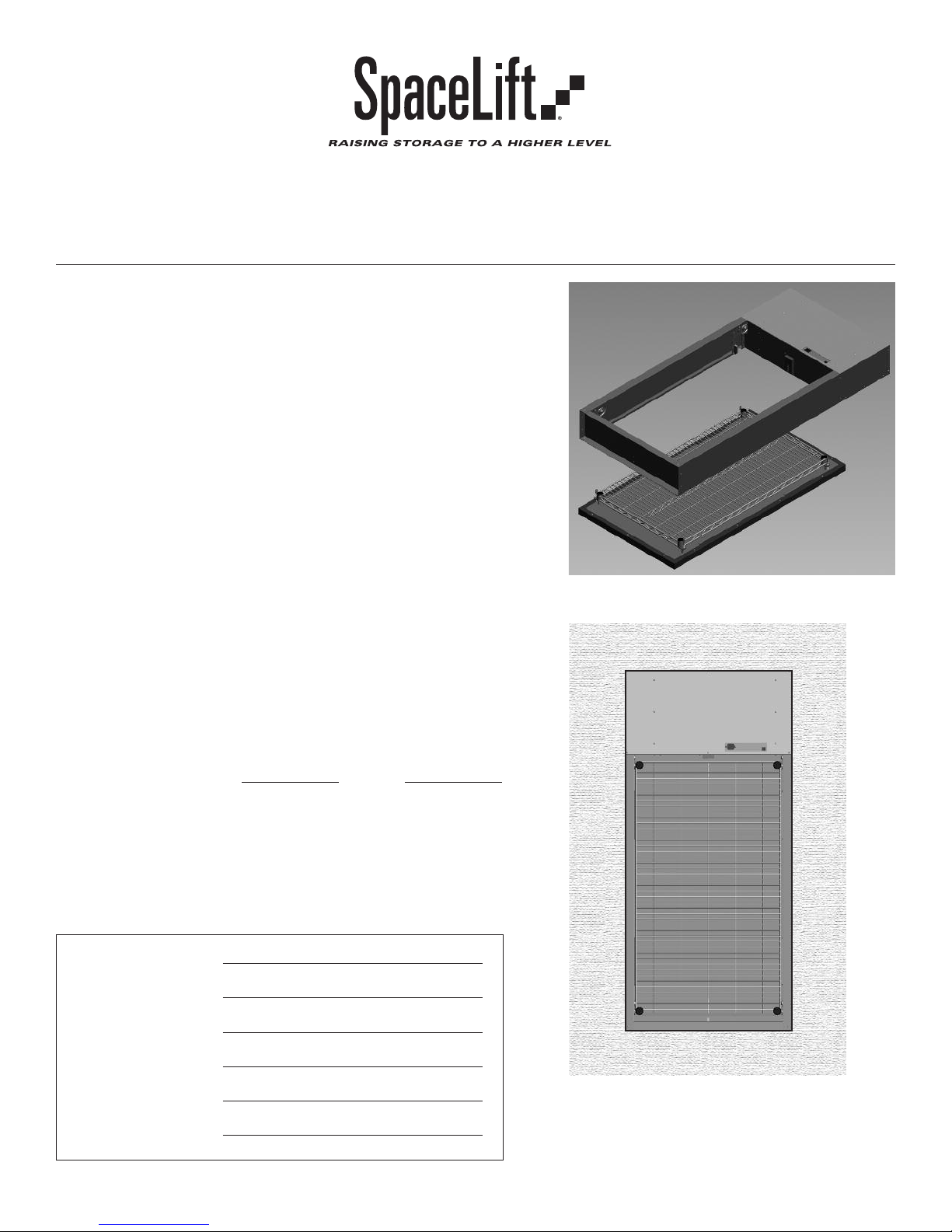
SpaceLift 5200 Series, operational perspective
Model 5222
Dimensions (inches}: 22 W x 59.5 L x 7 H 28 W x 59.5 L x 7 H
Rough Framed Opening: 22.5 x 60 (+/- 1/8) 28.5 x 60 (+/- 1/8)
Internal Platform Area: 18 x 41 24 x 41
Ceiling Drywall Cutout: 22.5 x 46 28.5 x 46
Landing Space Area: 24.5 x 48 30.5 x 48
Unit Weight: 75 lbs 88 lbs
Model Number:
Serial Number:
Installation Date:
Installer:
Place of Purchase:
Date of Purchase:
Page 1 SpaceLift 5200 Series Attic Lift Manual (10/14)
Model 5228
SpaceLift 5200 Series, view stowed in attic floor
Protected by U.S. Patent No. 8,292,031.
INSTALLATION INSTRUCTIONS
MPORTANT NOTE: Please read this manual completely before you install
I
and operate the lift. Installation of the SpaceLift 5200 Series attic lift
system should ONLY be performed by a qualified professional. Installation
of the 5200 Series lift systems require skills in carpentry and electrical
wiring. If you choose to have the lift system installed without the use
of a certified installer, you may void portions of the warranty.
BEFORE YOU BEGIN
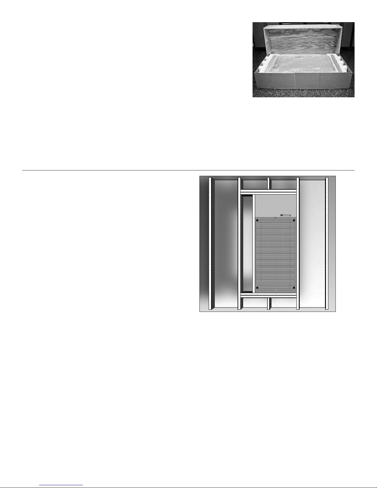
1. Open the shipping container and verify contents are
free of any damage that may have occurred during
transport. Check the Contents List to be sure everything
is included.
2. Contact your dealer if the lift system appears damaged.
3. Record the Model Number and Serial Number of the
lift system on the front page of this manual.
SECTION 1: LOCATION SELECTION
Select a location for installation. Your home must
have an acceptable ceiling and joist structure.
Consult a structural engineer before making any
modifications to the ceiling and joist structure and
to determine the load bearing capacity of the
selected installation area.
IMPORTANT NOTE: Secure ALL packing
and shipping material until installation is
complete and the unit is operating as
intended. These materials are required
should the unit be returned. If you discard,
and unit must be shipped, there will be
delays and additional charges.
LOCATION AND ORIENTATION REQUIREMENTS
• Orientation: Lift must be oriented such
that its length is parallel to the floor joists.
• Finished Floor: Top floor must be
finished with 1/2-inch to 3/4-inch plywood
or comparable material.
• Electrical Outlet: An electrical outlet must be
located within 4 feet of mounted lift system.
• Load Support: Floor must support loads as
specified in local residential building codes.
• Power Requirement: A dedicated 15 amp
circuit is required.
• Landing Area: Landing area for cargo tray with
attached ceiling cover (both on top and bottom
floor) must be clear of any obstructions.
• Travel Distance: The Maximum Vertical Travel
distance of the lift system is 15 feet with the
preferred travel distance set on the control
panel during the installation process.
• Ceiling Height: If the Floor to Ceiling Height is
greater than 15 feet, even at maximum deployment, the cargo lift platform will not reach the
Page 2 SpaceLift 5200 Series Attic Lift Manual (10/14)
SpaceLift Model 5228 installed in attic floor section
with 16-inch on center joists.
floor before stopping. The platform tray may be
loaded and unloaded above the floor, but the
operator should be sure the platform tray is not
swaying before raising the lift.
• Overhead Space: Allow at least 4 feet of
overhead space above the installation area
to provide lift access.
• Remote Control Unit: Remote Control Unit must be
mounted on an adjacent wall at least 4 feet above the
ground. Allow a clear line of sight between the
Remote Control Unit and the lift system clear of any
moving parts of the lift and any obstructions. Must
provide a wired Ethernet connection, from Remote
Control Unit to lift system, using standard CAT-5
cable.

SECTION 2: PREPARE THE OPENING
STEP 1: PREPARE A FRAMED OPENING IN THE CEILING
The optimal dimensions of the framed opening are
shown below. The framed opening must be square.
NOTE: Rough opening size must include allowance for
all penetrations such as joist hangers (if required). It may
be necessary to increase rough opening size slightly to
accommodate penetrations.
Required Installation Dimensions
• Maximum Vertical Travel: 15 feet
• Joist/Ceiling Drywall Depth: 7 to 14 inches
Model 5222 Model 5228
Rough Framed Opening: 22.5 x 60 (+/- 1/8) 28.5 x 60 (+/- 1/8)
Ceiling Drywall Cutout: 22.5 x 46 28.5 x 46
Landing Space Area: 24.5 x 48 30.5 x 48
NOTE: Ceiling drywall opening is smaller than, and centered
within, the Ceiling Cover. Measure and cut drywall carefully with
unit in place. Leave drywall section beneath motor side of unit.
CONTENTS INCLUDED WITH LIFT
• Remote Control Unit
• One Gang Electrical Box and Cat-5 Cable
• Ceiling Cover and Hardware Kit
ADDITIONAL MATERIALS REQUIRED
• Wood strips, two (2) 2-inch W x 2-inch H strips cut
to width of framed opening
• Sixteen (16) 16D nails (3-1/2”) and wood glue
• Additional wood strips, mounted on sides of
opening as desired for finished look, two (2)
1-inch W x 2-inch H wood strips approximately 56
inches long.
• Depending on attic access, a material lift may be
required to move the unit into attic space through
an attic door or the rough-cut opening in ceiling
drywall.
FLOOR SECTION
FRAMED ROUGH OPENING WITH 16-INCH ON CENTER JOISTS
Floor finished with 1/2 to 3/4 inch plywood before installation.
Measure and cut drywall carefully with unit in place. Leave
drywall section beneath motor side of unit.
NOTE: Model 5222 installed in attic floor with 24-inch on center
joists requires no joist cut or stringer.
STEP 2: INSTALL MOUNTING STRIPS
1. Cut 2-inch x 2-inch wood Mount Strips to width
of framed opening to fit inside short side of frame.
NOTE: If the rough opening size is increased to
accommodate joist hanger or other protrusion into
the recommended rough opening size, then increase
dimensions to accommodate the larger rough
opening size.
2. Set Mount Strips to be flush with bottom
of headers (see illustration). Level and install
with 16D nails (four each side) and glue.
3. Install Side Strips as desired for finished look. Measure
and cut 1-inch W x 2-inch H Side Strips (approximately
56-inches long), install 2-inch sides level with Mount
Strips on long sides with 16D nails (four each side)
and glue.
Page 3 SpaceLift 5200 Series Attic Lift Manual (10/14)
 Loading...