

SpaceCam Maximus 7 Operator And Maintenance Manual
MAXIMUS 7
OPERATOR’S
AND
MAINTENANCE
MANUAL
August 17, 2016
SPACECAM
SYSTEMS, INC.
31240 La Baya Dr. Ste. A
Westlake Village, CA. 91362
818-889-6060

SPACECAM
SYSTEMS, INC.
MAXIMUS 7 OPERATOR’S MANUAL
August 17, 2016
TABLE OF CONTENT
1 INTRODUCTION.. . . . . . . . . . . . . . . . . . . . . . . . . . . . . . . . . . . . . . . . . . . . . . . . . . . . . . . . . . . . . . . . . . . . . . . . 5
1.1 Warnings. . . . . . . . . . . . . . . . . . . . . . . . . . . . . . . . . . . . . . . . . . . . . . . . . . . . . . . . . . . . . . . . . . . . . . . . 5
1.2 Gimbal main operating modes.. . . . . . . . . . . . . . . . . . . . . . . . . . . . . . . . . . . . . . . . . . . . . . . . . . . . . . . 6
DISABLE.. . . . . . . . . . . . . . . . . . . . . . . . . . . . . . . . . . . . . . . . . . . . . . . . . . . . . . . . . . . . . . . . . . . . 6
SPACECAM. . . . . . . . . . . . . . . . . . . . . . . . . . . . . . . . . . . . . . . . . . . . . . . . . . . . . . . . . . . . . . . . . . 6
SPACECAM2. . . . . . . . . . . . . . . . . . . . . . . . . . . . . . . . . . . . . . . . . . . . . . . . . . . . . . . . . . . . . . . . . 6
ZEDIR/PAN.. . . . . . . . . . . . . . . . . . . . . . . . . . . . . . . . . . . . . . . . . . . . . . . . . . . . . . . . . . . . . . . . . . 6
HARD. . . . . . . . . . . . . . . . . . . . . . . . . . . . . . . . . . . . . . . . . . . . . . . . . . . . . . . . . . . . . . . . . . . . . . . 6
1.3 Gimbal sub operating modes. . . . . . . . . . . . . . . . . . . . . . . . . . . . . . . . . . . . . . . . . . . . . . . . . . . . . . . . . 7
Pan Modes. . . . . . . . . . . . . . . . . . . . . . . . . . . . . . . . . . . . . . . . . . . . . . . . . . . . . . . . . . . . . . . . . . . . 7
Yaw Velocity mode. . . . . . . . . . . . . . . . . . . . . . . . . . . . . . . . . . . . . . . . . . . . . . . . . . . . . . . 7
Yaw Follow mode. . . . . . . . . . . . . . . . . . . . . . . . . . . . . . . . . . . . . . . . . . . . . . . . . . . . . . . . 7
Tilt Modes. . . . . . . . . . . . . . . . . . . . . . . . . . . . . . . . . . . . . . . . . . . . . . . . . . . . . . . . . . . . . . . . . . . . 7
Pitch Velocity mode.. . . . . . . . . . . . . . . . . . . . . . . . . . . . . . . . . . . . . . . . . . . . . . . . . . . . . . 7
Pitch Follow mode. . . . . . . . . . . . . . . . . . . . . . . . . . . . . . . . . . . . . . . . . . . . . . . . . . . . . . . 7
Roll Modes.. . . . . . . . . . . . . . . . . . . . . . . . . . . . . . . . . . . . . . . . . . . . . . . . . . . . . . . . . . . . . . . . . . . 7
Roll Velocity mode. . . . . . . . . . . . . . . . . . . . . . . . . . . . . . . . . . . . . . . . . . . . . . . . . . . . . . . 7
Roll Follow mode. . . . . . . . . . . . . . . . . . . . . . . . . . . . . . . . . . . . . . . . . . . . . . . . . . . . . . . . 7
Roll Position mode.. . . . . . . . . . . . . . . . . . . . . . . . . . . . . . . . . . . . . . . . . . . . . . . . . . . . . . . 7
Level Roll.. . . . . . . . . . . . . . . . . . . . . . . . . . . . . . . . . . . . . . . . . . . . . . . . . . . . . . . . . . . . . . . . . . . . 7
2 CONFIGURATIONS. . . . . . . . . . . . . . . . . . . . . . . . . . . . . . . . . . . . . . . . . . . . . . . . . . . . . . . . . . . . . . . . . . . . . . 8
2.1 Minimum installation.. . . . . . . . . . . . . . . . . . . . . . . . . . . . . . . . . . . . . . . . . . . . . . . . . . . . . . . . . . . . . . 8
2.2 Installation with cable extensions. . . . . . . . . . . . . . . . . . . . . . . . . . . . . . . . . . . . . . . . . . . . . . . . . . . . . 9
2.3 Wireless installation.. . . . . . . . . . . . . . . . . . . . . . . . . . . . . . . . . . . . . . . . . . . . . . . . . . . . . . . . . . . . . . 10
2.4 Wheel’s installation. . . . . . . . . . . . . . . . . . . . . . . . . . . . . . . . . . . . . . . . . . . . . . . . . . . . . . . . . . . . . . . 11
2.5 Analog controls installation.. . . . . . . . . . . . . . . . . . . . . . . . . . . . . . . . . . . . . . . . . . . . . . . . . . . . . . . . 12
3 OPERATION. . . . . . . . . . . . . . . . . . . . . . . . . . . . . . . . . . . . . . . . . . . . . . . . . . . . . . . . . . . . . . . . . . . . . . . . . . . 13
3.1 Console key’s functions.. . . . . . . . . . . . . . . . . . . . . . . . . . . . . . . . . . . . . . . . . . . . . . . . . . . . . . . . . . . 13
3.2 Console operation. . . . . . . . . . . . . . . . . . . . . . . . . . . . . . . . . . . . . . . . . . . . . . . . . . . . . . . . . . . . . . . . 16
Screen colors. . . . . . . . . . . . . . . . . . . . . . . . . . . . . . . . . . . . . . . . . . . . . . . . . . . . . . . . . . . . . . . . . 16
3.2.2 Procedure to set a parameter.. . . . . . . . . . . . . . . . . . . . . . . . . . . . . . . . . . . . . . . . . . . . . . . . 16
3.2.3 Control device’s select and setup. . . . . . . . . . . . . . . . . . . . . . . . . . . . . . . . . . . . . . . . . . . . . 17
Direction.. . . . . . . . . . . . . . . . . . . . . . . . . . . . . . . . . . . . . . . . . . . . . . . . . . . . . . . . . . . . . . 18
Smoothing... . . . . . . . . . . . . . . . . . . . . . . . . . . . . . . . . . . . . . . . . . . . . . . . . . . . . . . . . . . . 18
Dead-band... . . . . . . . . . . . . . . . . . . . . . . . . . . . . . . . . . . . . . . . . . . . . . . . . . . . . . . . . . . . 18
PosLimTaper. . . . . . . . . . . . . . . . . . . . . . . . . . . . . . . . . . . . . . . . . . . . . . . . . . . . . . . . . . . 19
Select (¶ ) control device from main screen. . . . . . . . . . . . . . . . . . . . . . . . . . . . . . . . . . . 19
3.2.4 Option-1’s.. . . . . . . . . . . . . . . . . . . . . . . . . . . . . . . . . . . . . . . . . . . . . . . . . . . . . . . . . . . . . . 20
RollStick Spd.. . . . . . . . . . . . . . . . . . . . . . . . . . . . . . . . . . . . . . . . . . . . . . . . . . . . . . . . . . 20
RollStick Tpr. . . . . . . . . . . . . . . . . . . . . . . . . . . . . . . . . . . . . . . . . . . . . . . . . . . . . . . . . . . 20
31240 La Baya Dr. Ste. A
Westlake Village, CA. 91362
818-889-6060
Page 2 of 74

SPACECAM
SYSTEMS, INC.
3.2.5 Option-2’s.. . . . . . . . . . . . . . . . . . . . . . . . . . . . . . . . . . . . . . . . . . . . . . . . . . . . . . . . . . . . . . 21
3.2.6 Zoom auto Pan-Tilt sense control.. . . . . . . . . . . . . . . . . . . . . . . . . . . . . . . . . . . . . . . . . . . . 22
3.2.7 Gimbal Setup. . . . . . . . . . . . . . . . . . . . . . . . . . . . . . . . . . . . . . . . . . . . . . . . . . . . . . . . . . . . 23
3.2.8 Wired lens control setups. . . . . . . . . . . . . . . . . . . . . . . . . . . . . . . . . . . . . . . . . . . . . . . . . . . 24
3.2.9 Reset All. . . . . . . . . . . . . . . . . . . . . . . . . . . . . . . . . . . . . . . . . . . . . . . . . . . . . . . . . . . . . . . . 27
3.2.10 Version. . . . . . . . . . . . . . . . . . . . . . . . . . . . . . . . . . . . . . . . . . . . . . . . . . . . . . . . . . . . . . . . 28
3.2.11 Motion recording and playback. . . . . . . . . . . . . . . . . . . . . . . . . . . . . . . . . . . . . . . . . . . . . 28
3.2.12 Mark recording and playback. . . . . . . . . . . . . . . . . . . . . . . . . . . . . . . . . . . . . . . . . . . . . . . 28
3.2.13 Stability and Master Gain. . . . . . . . . . . . . . . . . . . . . . . . . . . . . . . . . . . . . . . . . . . . . . . . . . 29
3.2.14 Disengage (freeze). . . . . . . . . . . . . . . . . . . . . . . . . . . . . . . . . . . . . . . . . . . . . . . . . . . . . . . 30
3.2.15 Gimbal drift.. . . . . . . . . . . . . . . . . . . . . . . . . . . . . . . . . . . . . . . . . . . . . . . . . . . . . . . . . . . . 30
3.2.16 Joysticks drift. . . . . . . . . . . . . . . . . . . . . . . . . . . . . . . . . . . . . . . . . . . . . . . . . . . . . . . . . . . 30
3.3 Data transfer Console to PC.. . . . . . . . . . . . . . . . . . . . . . . . . . . . . . . . . . . . . . . . . . . . . . . . . . . . . . . . 31
3.3.1 Setting up the connection. . . . . . . . . . . . . . . . . . . . . . . . . . . . . . . . . . . . . . . . . . . . . . . . . . . 31
3.3.2 Data format. . . . . . . . . . . . . . . . . . . . . . . . . . . . . . . . . . . . . . . . . . . . . . . . . . . . . . . . . . . . . . 31
MAXIMUS 7 OPERATOR’S MANUAL
August 17, 2016
Yaw follow.. . . . . . . . . . . . . . . . . . . . . . . . . . . . . . . . . . . . . . . . . . . . . . . . . . . . . . . . . . . . 20
Pitch follow. . . . . . . . . . . . . . . . . . . . . . . . . . . . . . . . . . . . . . . . . . . . . . . . . . . . . . . . . . . . 20
Roll follow.. . . . . . . . . . . . . . . . . . . . . . . . . . . . . . . . . . . . . . . . . . . . . . . . . . . . . . . . . . . . 20
Encoder scale.. . . . . . . . . . . . . . . . . . . . . . . . . . . . . . . . . . . . . . . . . . . . . . . . . . . . . . . . . . 20
Swap Joysticks.. . . . . . . . . . . . . . . . . . . . . . . . . . . . . . . . . . . . . . . . . . . . . . . . . . . . . . . . . 21
Swap Arm Control.. . . . . . . . . . . . . . . . . . . . . . . . . . . . . . . . . . . . . . . . . . . . . . . . . . . . . . 21
Stick property.. . . . . . . . . . . . . . . . . . . . . . . . . . . . . . . . . . . . . . . . . . . . . . . . . . . . . . . . . . 21
Ext.Whl.Freeze. . . . . . . . . . . . . . . . . . . . . . . . . . . . . . . . . . . . . . . . . . . . . . . . . . . . . . . . . 21
Clink PRate. . . . . . . . . . . . . . . . . . . . . . . . . . . . . . . . . . . . . . . . . . . . . . . . . . . . . . . . . . . . 21
Clink Mode. . . . . . . . . . . . . . . . . . . . . . . . . . . . . . . . . . . . . . . . . . . . . . . . . . . . . . . . . . . . 22
Setting axes’ Master Gains. . . . . . . . . . . . . . . . . . . . . . . . . . . . . . . . . . . . . . . . . . . . . . . . 23
Setting axes’ Home Positions. . . . . . . . . . . . . . . . . . . . . . . . . . . . . . . . . . . . . . . . . . . . . . 23
Analog POTs. . . . . . . . . . . . . . . . . . . . . . . . . . . . . . . . . . . . . . . . . . . . . . . . . . . . . . . . . . . 24
Preston analog option.. . . . . . . . . . . . . . . . . . . . . . . . . . . . . . . . . . . . . . . . . . . . . . . . . . . . 24
LimeRock option. . . . . . . . . . . . . . . . . . . . . . . . . . . . . . . . . . . . . . . . . . . . . . . . . . . . . . . . 25
Cmotion option. . . . . . . . . . . . . . . . . . . . . . . . . . . . . . . . . . . . . . . . . . . . . . . . . . . . . . . . . 26
4 THE GIMBAL. . . . . . . . . . . . . . . . . . . . . . . . . . . . . . . . . . . . . . . . . . . . . . . . . . . . . . . . . . . . . . . . . . . . . . . . . . 32
4.1 Gimbal main parts naming.. . . . . . . . . . . . . . . . . . . . . . . . . . . . . . . . . . . . . . . . . . . . . . . . . . . . . . . . . 32
4.2 Installing a camera.. . . . . . . . . . . . . . . . . . . . . . . . . . . . . . . . . . . . . . . . . . . . . . . . . . . . . . . . . . . . . . . 33
4.3 Balancing the payload. . . . . . . . . . . . . . . . . . . . . . . . . . . . . . . . . . . . . . . . . . . . . . . . . . . . . . . . . . . . . 34
4.4 Axes’ Home Positions Setup.. . . . . . . . . . . . . . . . . . . . . . . . . . . . . . . . . . . . . . . . . . . . . . . . . . . . . . . 35
4.5 LED Box... . . . . . . . . . . . . . . . . . . . . . . . . . . . . . . . . . . . . . . . . . . . . . . . . . . . . . . . . . . . . . . . . . . . . . 36
5 SYSTEM CONNECTIONS, INDICATORS AND CONTROL... . . . . . . . . . . . . . . . . . . . . . . . . . . . . . . . . . . 37
5.1 Console Connectors.. . . . . . . . . . . . . . . . . . . . . . . . . . . . . . . . . . . . . . . . . . . . . . . . . . . . . . . . . . . . . . 37
5.2 Platform Saddle Connectors. . . . . . . . . . . . . . . . . . . . . . . . . . . . . . . . . . . . . . . . . . . . . . . . . . . . . . . . 44
5.3 Twist Ring Connectors. . . . . . . . . . . . . . . . . . . . . . . . . . . . . . . . . . . . . . . . . . . . . . . . . . . . . . . . . . . . 47
5.4 Turret Connectors. . . . . . . . . . . . . . . . . . . . . . . . . . . . . . . . . . . . . . . . . . . . . . . . . . . . . . . . . . . . . . . . 48
31240 La Baya Dr. Ste. A
Page 3 of 74
Westlake Village, CA. 91362
818-889-6060

SPACECAM
SYSTEMS, INC.
MAXIMUS 7 OPERATOR’S MANUAL
August 17, 2016
5.5 Indicators on the turret.. . . . . . . . . . . . . . . . . . . . . . . . . . . . . . . . . . . . . . . . . . . . . . . . . . . . . . . . . . . . 50
5.6 System Power Supply Connectors.. . . . . . . . . . . . . . . . . . . . . . . . . . . . . . . . . . . . . . . . . . . . . . . . . . . 51
5.7 Platform Power Supply Connectors.. . . . . . . . . . . . . . . . . . . . . . . . . . . . . . . . . . . . . . . . . . . . . . . . . . 54
5.8 The Maintenance switch and Tilt lock.. . . . . . . . . . . . . . . . . . . . . . . . . . . . . . . . . . . . . . . . . . . . . . . . 56
5.9 Connecting a PC to the gimbal.. . . . . . . . . . . . . . . . . . . . . . . . . . . . . . . . . . . . . . . . . . . . . . . . . . . . . . 56
6 MAINTENANCE TOOL. . . . . . . . . . . . . . . . . . . . . . . . . . . . . . . . . . . . . . . . . . . . . . . . . . . . . . . . . . . . . . . . . . 57
6.1 Installing the Maintenance Tool. . . . . . . . . . . . . . . . . . . . . . . . . . . . . . . . . . . . . . . . . . . . . . . . . . . . . 57
6.2 Uninstalling the Maintenance Tool. . . . . . . . . . . . . . . . . . . . . . . . . . . . . . . . . . . . . . . . . . . . . . . . . . . 57
6.3 The content of the Maintenance Tool’s installation directory. . . . . . . . . . . . . . . . . . . . . . . . . . . . . . . 57
6.4 Maintenance Tool main screen. . . . . . . . . . . . . . . . . . . . . . . . . . . . . . . . . . . . . . . . . . . . . . . . . . . . . . 58
6.5 Saving the parameters. . . . . . . . . . . . . . . . . . . . . . . . . . . . . . . . . . . . . . . . . . . . . . . . . . . . . . . . . . . . . 58
6.6 Printing the parameters. . . . . . . . . . . . . . . . . . . . . . . . . . . . . . . . . . . . . . . . . . . . . . . . . . . . . . . . . . . . 58
6.7 Maintenance Tool, Gimbal tab. . . . . . . . . . . . . . . . . . . . . . . . . . . . . . . . . . . . . . . . . . . . . . . . . . . . . . 59
6.8 Maintenance Tool, Servo Parameters tab. . . . . . . . . . . . . . . . . . . . . . . . . . . . . . . . . . . . . . . . . . . . . . 60
6.8.1 The Train axis table. . . . . . . . . . . . . . . . . . . . . . . . . . . . . . . . . . . . . . . . . . . . . . . . . . . . . . . 61
6.8.2 The Tilt axis table. . . . . . . . . . . . . . . . . . . . . . . . . . . . . . . . . . . . . . . . . . . . . . . . . . . . . . . . . 62
6.8.3 The Pan axis table.. . . . . . . . . . . . . . . . . . . . . . . . . . . . . . . . . . . . . . . . . . . . . . . . . . . . . . . . 63
6.8.4 The Twist axis table. . . . . . . . . . . . . . . . . . . . . . . . . . . . . . . . . . . . . . . . . . . . . . . . . . . . . . . 64
6.9 Maintenance Tool, General Parameters tab.. . . . . . . . . . . . . . . . . . . . . . . . . . . . . . . . . . . . . . . . . . . . 65
6.10 Maintenance Tool Err&Info tab.. . . . . . . . . . . . . . . . . . . . . . . . . . . . . . . . . . . . . . . . . . . . . . . . . . . . 66
6.11 Flashing the Gimbal Controller with the Maintenance Tool program.. . . . . . . . . . . . . . . . . . . . . . . 67
7 BOOT LOADER.. . . . . . . . . . . . . . . . . . . . . . . . . . . . . . . . . . . . . . . . . . . . . . . . . . . . . . . . . . . . . . . . . . . . . . . . 69
7.1 Flashing the Gimbal Controller with the boot-loader. . . . . . . . . . . . . . . . . . . . . . . . . . . . . . . . . . . . . 69
8 MAINTENANCE.. . . . . . . . . . . . . . . . . . . . . . . . . . . . . . . . . . . . . . . . . . . . . . . . . . . . . . . . . . . . . . . . . . . . . . . 71
8.1 Tilt, Pan and Train Encoder Cleaning... . . . . . . . . . . . . . . . . . . . . . . . . . . . . . . . . . . . . . . . . . . . . . . . 71
9 PARTS LIST.. . . . . . . . . . . . . . . . . . . . . . . . . . . . . . . . . . . . . . . . . . . . . . . . . . . . . . . . . . . . . . . . . . . . . . . . . . . 72
10 SPECIFICATIONS.. . . . . . . . . . . . . . . . . . . . . . . . . . . . . . . . . . . . . . . . . . . . . . . . . . . . . . . . . . . . . . . . . . . . . 73
TABLES
TABLE 1 - Gimbal operating modes. . . . . . . . . . . . . . . . . . . . . . . . . . . . . . . . . . . . . . . . . . . . . . . . . . . . . . . . . . . 6
TABLE 2 - Console key’s functions.. . . . . . . . . . . . . . . . . . . . . . . . . . . . . . . . . . . . . . . . . . . . . . . . . . . . . . . . . . 13
TABLE 3 - Console Connectors.. . . . . . . . . . . . . . . . . . . . . . . . . . . . . . . . . . . . . . . . . . . . . . . . . . . . . . . . . . . . . 37
TABLE 4 - Platform Saddle Connectors. . . . . . . . . . . . . . . . . . . . . . . . . . . . . . . . . . . . . . . . . . . . . . . . . . . . . . . 44
TABLE 5 - Twist Ring Connectors. . . . . . . . . . . . . . . . . . . . . . . . . . . . . . . . . . . . . . . . . . . . . . . . . . . . . . . . . . . 47
TABLE 6 - Turret Connectors. . . . . . . . . . . . . . . . . . . . . . . . . . . . . . . . . . . . . . . . . . . . . . . . . . . . . . . . . . . . . . . 48
TABLE 7 - Indicators on the turret.. . . . . . . . . . . . . . . . . . . . . . . . . . . . . . . . . . . . . . . . . . . . . . . . . . . . . . . . . . . 50
TABLE 8 - System Power Supply Connectors.. . . . . . . . . . . . . . . . . . . . . . . . . . . . . . . . . . . . . . . . . . . . . . . . . . 51
TABLE 9 - Platform Power Supply Connectors.. . . . . . . . . . . . . . . . . . . . . . . . . . . . . . . . . . . . . . . . . . . . . . . . . 54
31240 La Baya Dr. Ste. A
Westlake Village, CA. 91362
818-889-6060
Page 4 of 74

SPACECAM
SYSTEMS, INC.
1 INTRODUCTION
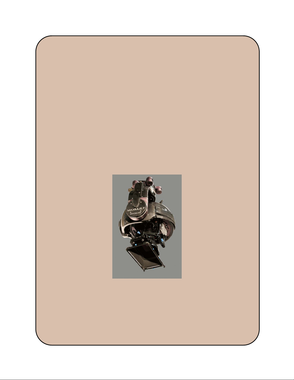
The SpaceCam Maximus 7stabilized gimbal system is the latest development from the SpaceCam team.
The Maximus is a 7 axis light weight, gyro stabilized mounting and steering system for high end film
cameras. It provides 360 degree continuous steering in pan, tilt and roll axes with an architecture that
totally avoids gimbal lock in all positions. Additionally, the base mounting position can be oriented in
any attitude, top, bottom or cantilevered (matrix). The Maximus also allows full transition between these
positions during shooting while still maintaining control and stability.
The degree of stability and control easily transcends competing systems for crane, camera car and boat
applications.
As with any system it is highly recommended that technicians study and familiarize themselves with the
set up and operating principals in order to obtain the best quality imagery.
1.1 Warnings
We designed the system to have a long life and be reliable (as long as it is not modified). The system
power supply for example protects the system from trouble, over/under and reverse voltage and also
supplies the current demand correctly.
MAXIMUS 7 OPERATOR’S MANUAL
August 17, 2016
Customers and operators should not alter any part of the unit or invent new ways of system setup. If they
do
- Customers who bought a system lose their warranty and must pay for the repair.
- Customers who have a rental or demo unit should be responsible for the cost of repair or a
replacement system.
31240 La Baya Dr. Ste. A
Westlake Village, CA. 91362
818-889-6060
Page 5 of 74
SPACECAM
SYSTEMS, INC.
1.2 Gimbal main operating modes
MODE NOTE
DISABLE Gimbal servos are disabled
SPACECAM This mode mimics the way the original SpaceCam System operated with
MAXIMUS 7 OPERATOR’S MANUAL
August 17, 2016
TABLE 1 - Gimbal operating modes
the embellishment of being able to allow 360 degree continuous tilting and
rolling of the camera platform.
The camera's tilt axis is always aligned to the horizon. The camera can tilt
up and down and the top and bottom of the image frame is always parallel
to the horizon.
The camera has full 360 degree of tilt freedom while still keeping the top
and bottom of the image frame parallel to the horizon.
When the camera is pointed straight down or straight up a sideways pan
input on the joystick will result in the image rotating in the viewfinder.
This effect transitions to a pure pan motion of the camera as it is tilted up to
horizontal.
SPACECAM2 This mode is the same as SpaceCam mode with the additional feature that
control polarity is maintained even when the camera is in an inverted
position.
ZEDIR/PAN This mode starting with the camera at zero degrees tilt has the horizon level
in the frame.
When the camera is tilted down a transition happens that allows the
operator to pan the camera, in terms of image either left or right. This will
begin at -30 and transition to full image pan authority at -60 degrees in the
case of tilting the camera down. Upon tilting up the camera will transition
to a level state in roll between -60 and -30 degrees. This will happen in
time for the top of frame to be parallel with the horizon by the time it enters
the image frame. This feature will also be applicable when pointing the
camera above the horizon going to zenith.
In all cases the horizon when in image frame will be level in terms of
picture roll
HARD In hard mode the gimbal will follow the mounting bracket in all directions
(like welded). The joystick controls still work but there is no stabilization.
Select the desired gimbal mode with the F1 and F3 keys. Press F1 to disable the head and press F3
(repeat if needed) to select one of the 4 operating modes.
31240 La Baya Dr. Ste. A
Westlake Village, CA. 91362
818-889-6060
Page 6 of 74

SPACECAM
SYSTEMS, INC.
1.3 Gimbal sub operating modes
Pan Modes.
In the Yaw Velocity mode the yaw velocity of the platform is proportional to the pan joystick’s
displacement.
In the Yaw Follow mode the platform will follow the mounting bracket’s yaw movements in
addition to the joystick control. Press PAN. In follow mode the position limits don’t work!
Tilt Modes.
In the Pitch Velocity mode the pitch velocity of the platform is proportional to the tilt joystick’s
displacement.
In the Pitch Follow mode the platform will follow the mounting bracket’s pitch movements in
addition to the joystick control. Press TILT. In follow mode the position limits don’t work!
MAXIMUS 7 OPERATOR’S MANUAL
August 17, 2016
Roll Modes.
In the Roll Velocity mode the roll velocity of the platform is proportional to the roll joystick’s
displacement.
In the Roll Follow mode the platform will follow the mounting bracket’s roll movements in addition
to the joystick control. Press ROLL. In follow mode the position limits don’t work!
In the Roll Position mode the roll position of the platform is proportional to the joystick’s
displacement. Press (SHIFT)ROLL. In roll position mode the position limits don’t work!
Select the desired roll joystick mode in the Options Menu.
Level Roll.
Press F2 any time to level the roll axis of the platform.
31240 La Baya Dr. Ste. A
Westlake Village, CA. 91362
818-889-6060
Page 7 of 74
SPACECAM
SYSTEMS, INC.
2 CONFIGURATIONS
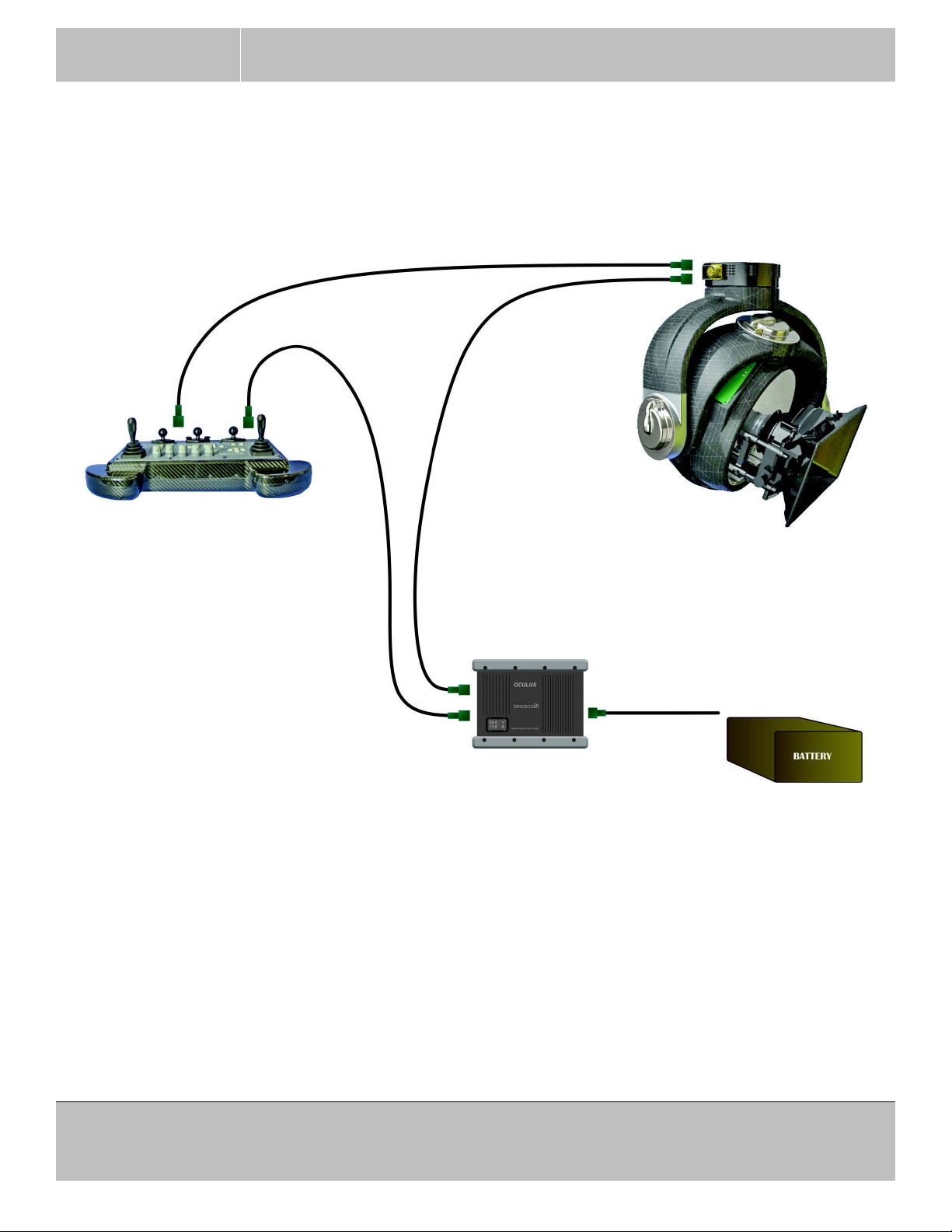
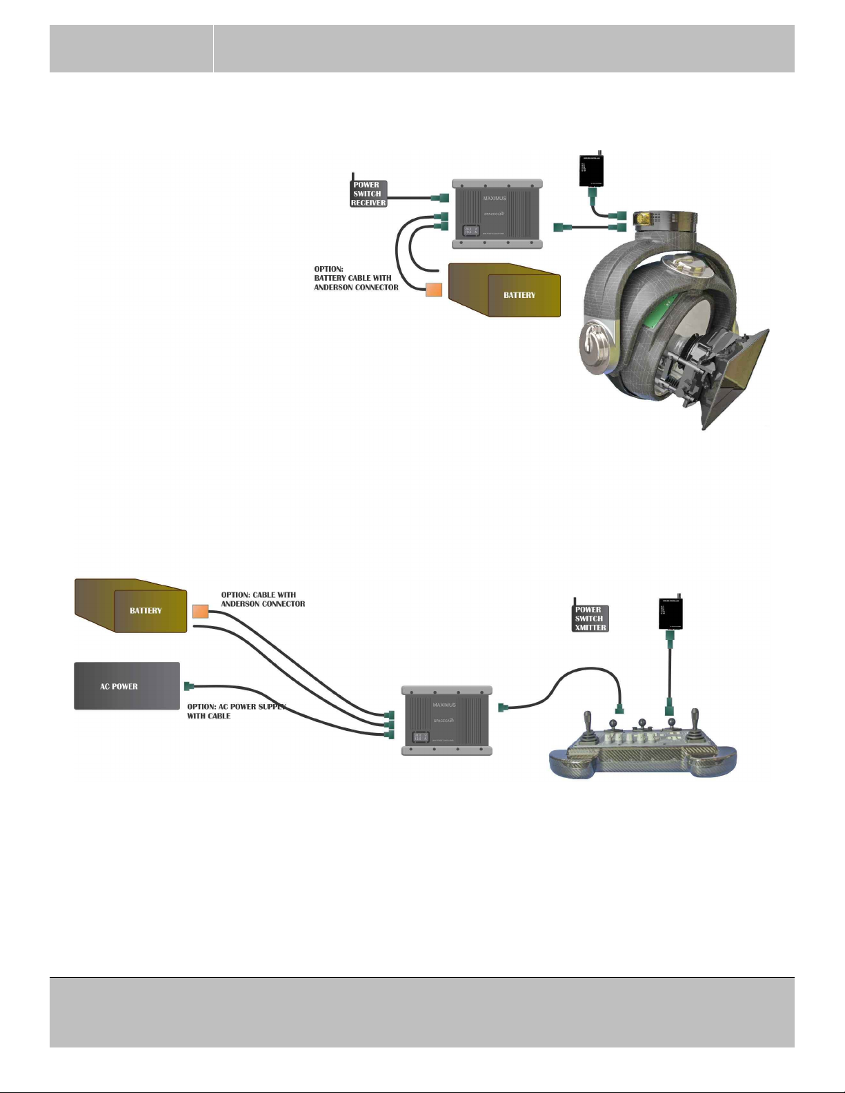
2.1 Minimum installation
MAXIMUS 7 OPERATOR’S MANUAL
OLS80302
OLS80301
OLS80300
August 17, 2016
Use the indicators on the System Power Supply to verify the correct polarity of the battery connection. If
the REV LED is red, then the input power is reversed. The STBY LED indicates that the correct power is
present at the power input connector. The STBY LED will not light up if the voltage is less than 18VDC or
reversed.
If the system is powered up and turns off automatically due to a power glitch or low voltage, the power only
can be turned on again manually with the ON switch on the console.
31240 La Baya Dr. Ste. A
Page 8 of 74
Westlake Village, CA. 91362
818-889-6060
SPACECAM
SYSTEMS, INC.
MAXIMUS 7 OPERATOR’S MANUAL
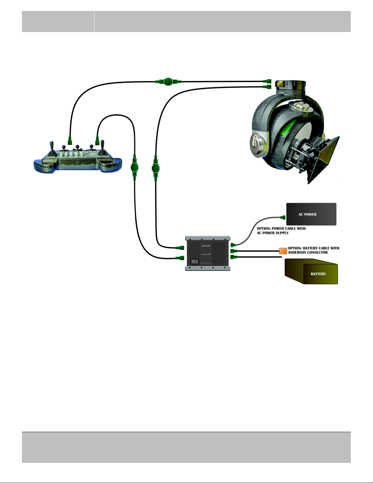
2.2 Installation with cable extensions
August 17, 2016
OLS80302
OLS80301
OLS80301
OLS80302
OLS80300
OLS80300
In case the distance between the main parts of the Maximus system is larger then the length of the standard
cables the cables can be extended using coupler boxes and spare cables. The total length of an extended
cable can not be longer than 150 feet. If longer distances required use the wireless configuration.
The System Power Supply can be connected to a battery with the standard cable that has bare wires on the
battery end and the users must install their own battery connector. Maximus also has cables with Anderson
connectors installed. There is also an AC Power Supply with cable that can be used if a battery is not
available. The AC power supply runs on 100 ~ 260 VAC.
31240 La Baya Dr. Ste. A
Page 9 of 74
Westlake Village, CA. 91362
818-889-6060
SPACECAM
SYSTEMS, INC.
2.3 Wireless installation
MAXIMUS 7 OPERATOR’S MANUAL
August 17, 2016
31240 La Baya Dr. Ste. A
Westlake Village, CA. 91362
818-889-6060
Page 10 of 74
SPACECAM
SYSTEMS, INC.
MAXIMUS 7 OPERATOR’S MANUAL
August 17, 2016
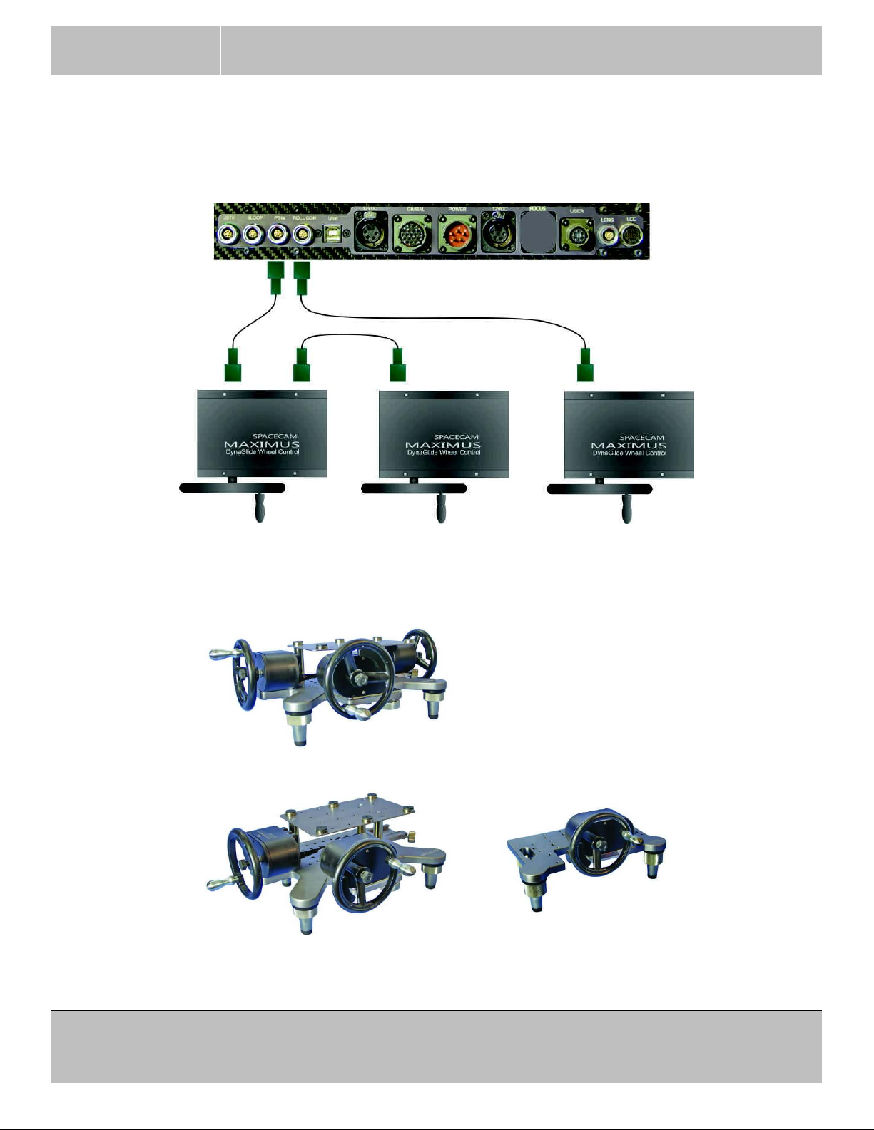
2.4 Wheel’s installation
The pan and tilt wheels connect to the PBW connector on the back of the console and the roll wheel
connects to the ROLL connector.
All three wheels can be mounted on the console stand or the roll can be mounted individually on it’s own
stand.
Pan, tilt and roll on console stand
Pan and tilt on console stand and roll is on it’s own stand
31240 La Baya Dr. Ste. A
Westlake Village, CA. 91362
818-889-6060
Page 11 of 74
SPACECAM
SYSTEMS, INC.
MAXIMUS 7 OPERATOR’S MANUAL
August 17, 2016
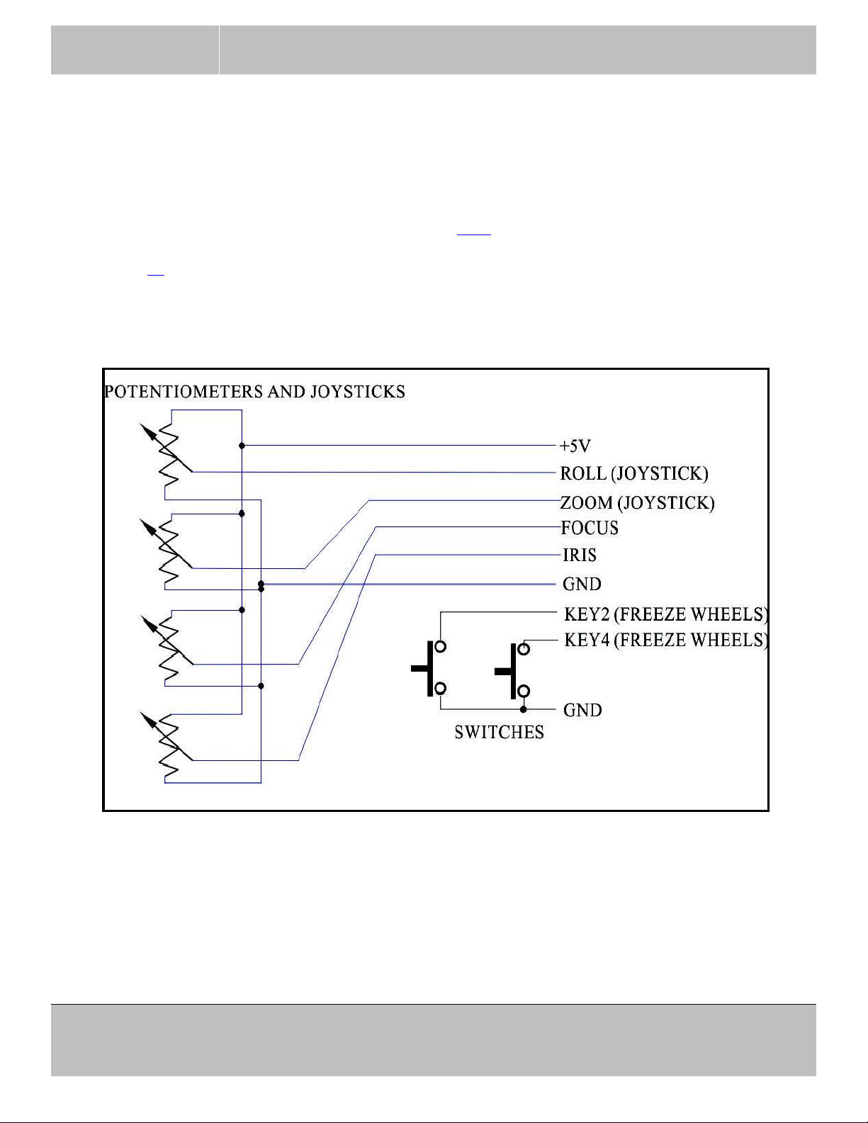
2.5 Analog controls installation
This connection is an upgrade!
Analog controls can connect to the ANA(LOG) connector on the back of the console. (Formal BLOOP).
It is possible to control roll, zoom, focus and iris using these analog inputs. SpaceCam did not develop
actual controllers for these analog inputs as of today. External wheel and pan-bar encoder freeze keys are
also connected to this connector. (See Menu Option-2. 3.2.5)
See page 38 for definitions of the signals on the connector. Contact SpaceCam if you decide to use these
functions.
Typical connections:
Figure 7 ANALOG CONTROLS SUGGESTED WIRING
Do not draw more than 50 mA from the +5V power. Good and safe choice for POTs would be between
2KΩ and 10KΩ. The joystick type inputs (Roll and Zoom) are nulled when the SHIFT(NULL) key is
pressed. That is when the software will take the sampled value as center.
Make sure that the +5V pin is not shorted to GND! There is no short current protection on that pin.
31240 La Baya Dr. Ste. A
Page 12 of 74
Westlake Village, CA. 91362
818-889-6060
SPACECAM
SYSTEMS, INC.
3 OPERATION
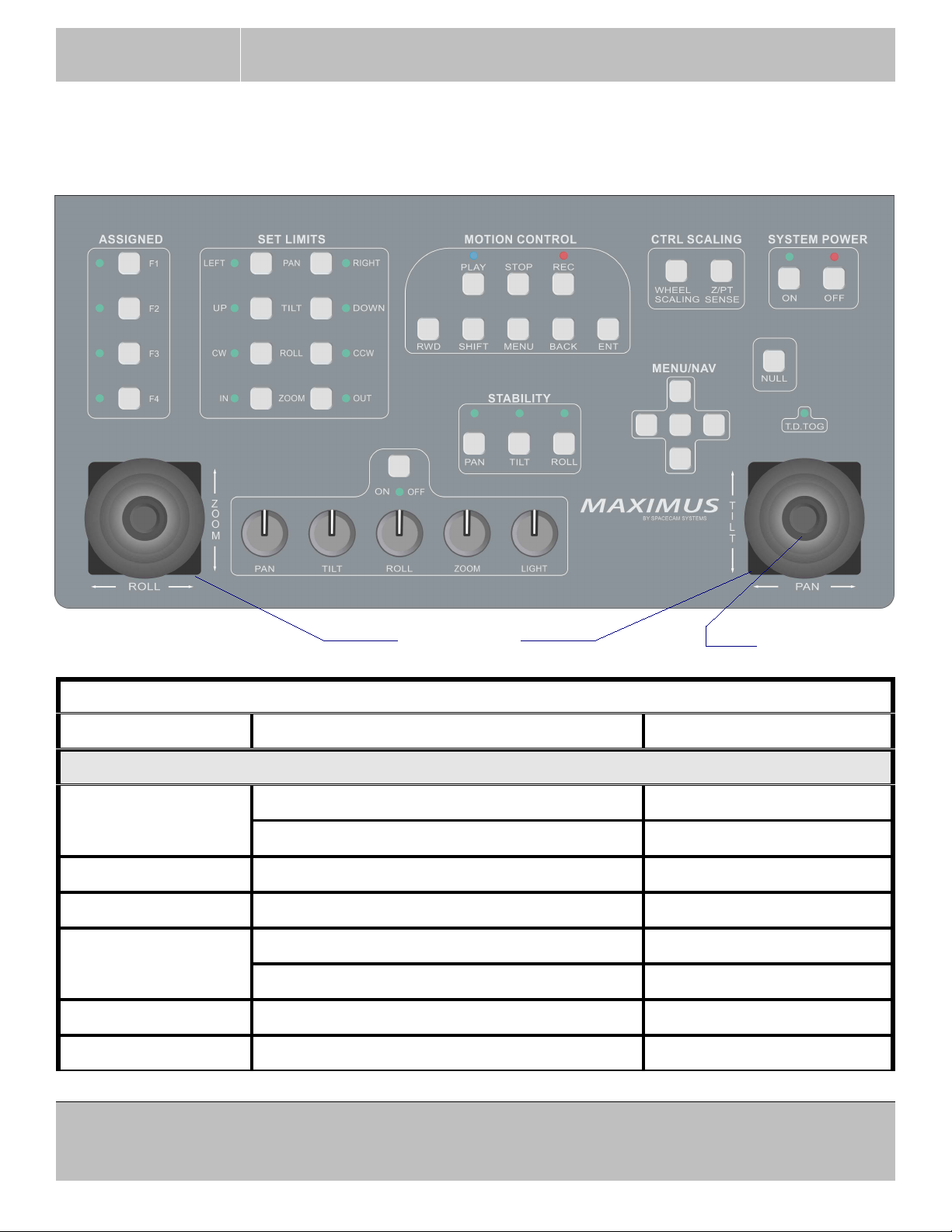
3.1 Console key’s functions
MAXIMUS 7 OPERATOR’S MANUAL
August 17, 2016
JOYSTICKS T.D.TOG
TABLE 2 - Console key’s functions
KEY FUNCTION NOTES
MOTION CONTROL GROUP
PLAY Play selected take. If a take is selected
Go to selected mark. If a mark is selected
(STOP) PLAY Delete all takes If a take is selected
STOP Stop record or play
REC Record selected take. If a take is selected
Record selected mark. If a mark is selected
(STOP) REC Delete current take
RWD Go to start of selected take. If a take is selected
31240 La Baya Dr. Ste. A
Westlake Village, CA. 91362
818-889-6060
Page 13 of 74
SPACECAM
SYSTEMS, INC.
MAXIMUS 7 OPERATOR’S MANUAL
August 17, 2016
TABLE 2 - Console key’s functions
KEY FUNCTION NOTES
(SHIFT) RWD Go to end of selected take. If a take is selected
SHIFT Modifier key.
MENU Calls the menu.
In menu returns to normal screen.
BACK Cancel current setup.
Move to the previous screen.
ENT Apply .....
MENU/NAV GROUP
UP, DOWN
Move to next or previous box.
LEFT, RIGHT
Increment or decrement a value.
(SHIFT) UP
(SHIFT) DOWN
In some setup frames
increments or decrements value 10 times faster.
CENTER KEY Same as ENT
CTRL SCALING GROUP
WHEEL SCALING Disengage wheels as long as this key is held
(Freeze)
down.
Z/PT SENSE Set zoom pan/tilt scaling Toggles Z/PT menu
ASSIGNED GROUP
F1 Disable gimbal
F2 Level roll
F3 Select gimbal mode. Enable if currently disabled.
F4 Display Master Gain
hold F4 Display and modify Master Gain Use up/down keys
SET LIMITS GROUP
31240 La Baya Dr. Ste. A
Westlake Village, CA. 91362
818-889-6060
Page 14 of 74
SPACECAM
SYSTEMS, INC.
MAXIMUS 7 OPERATOR’S MANUAL
TABLE 2 - Console key’s functions
KEY FUNCTION NOTES
PAN-LEFT Set pan left limit
August 17, 2016
PAN-RIGHT Set pan right limit
TILT-UP Set tilt up limit
The limits do not work in
follow modes and Roll
Position mode.
TILT-DOWN Set tilt down limit
ROLL-CW Set roll clockwise limit
ROLL-CCW Set roll counterclockwise limit
ZOOM-IN Set zoom in limit
ZOOM-OUT Set zoom out limit
STABILITY GROUP
PAN Pan normal or follow mode toggle. Normal mode holds
orientation of payload.
TILT Tilt hold orientation or follow mode toggle.
ROLL Roll hold orientation or follow mode toggle.
Follow mode follows the
mounting bracket.
(SHIFT) ROLL Roll stick Velocity or Position control mode
toggle.
OTHER KEYS
NULL Cancel gyro drift.
(SHIFT)NULL Cancel joystick’s drift.
(STOP)NULL Reset LCD screen.
(SHIFT)T.D.TOG Reverse tilt control direction. (Tilt Dir Toggle) On top of right joystick.
Camera Record Run and stop camera.
1
On top of left joystick.
Z/PT ON/OFF Zoom pan/tilt scaling setup.
SCALES_ON N/A Above ROLL scale knob.
(SHIFT) SCALES_ON Monitor lens controls and external switches.
(1) Function not available.
31240 La Baya Dr. Ste. A
Page 15 of 74
Westlake Village, CA. 91362
818-889-6060

SPACECAM
SYSTEMS, INC.
3.2 Console operation
The ENT key and the center key of the navigation pad have the same functions:
ENTER, ACCEPT, YES.
3.2.1 Screen colors.
The screen is colored to distinguish individual groups of information. There are two colors that have
special and important meanings.
RED There is an condition preventing the gimbal from operation.
BROWN There is a warning but the gimbal still could be operated.
3.2.2 Procedure to set a parameter.
Select: Move to desired field with the arrow keys.
Set: Set desired value with the arrow keys.
MAXIMUS 7 OPERATOR’S MANUAL
August 17, 2016
Press ENT to set change mode.
On some fields hold arrow key for continuous change.
On some fields press SHIFT concurrently to increase the step 10 fold.
Press ENT to enter the new value or BACK to return original value.
31240 La Baya Dr. Ste. A
Westlake Village, CA. 91362
818-889-6060
Page 16 of 74
SPACECAM
SYSTEMS, INC.
MAXIMUS 7 OPERATOR’S MANUAL
August 17, 2016
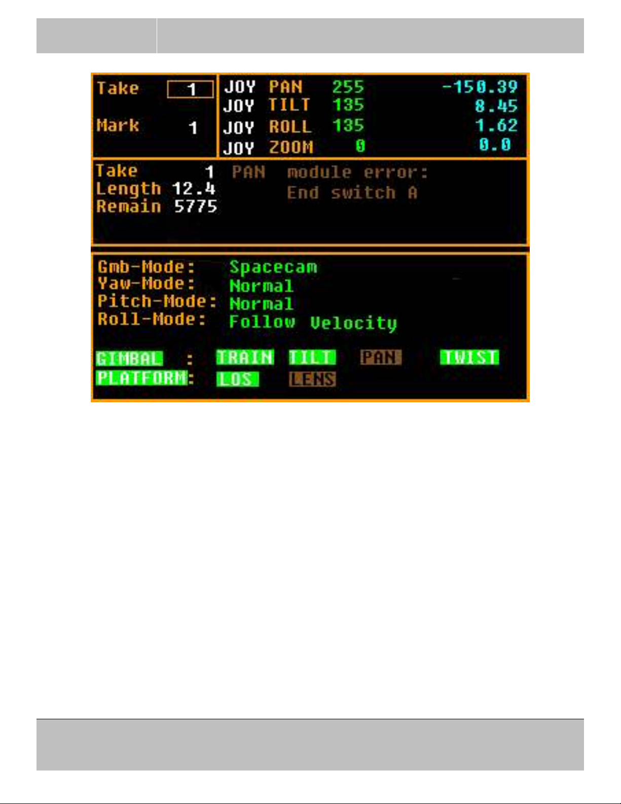
For example on the screen above the field the Take number is in focus (box around it).
To change the pan control device move the focus box with the arrow keys to the right to place it on pan’s
JOY(stick) field. Press ENTER, the box will blink. Select new control device for pan with the up/down
arrow keys and press ENTER again.
3.2.3 Control device’s select and setup:
The control devices move the 3 axes (pan, tilt and roll) in the desired direction.
There are four type of devices:
Console’s built in joysticks. JOY
Wheels. WHL
External joystick. JEX
Pan-bar. BAR
The external joystick is very useful in vibrating environments, because it isolates the vibration from the
control if held in the operator’s hand.
To quicky set a control device in the main screen with the arrow keys move the focus to the desired
31240 La Baya Dr. Ste. A
Westlake Village, CA. 91362
818-889-6060
Page 17 of 74
SPACECAM
SYSTEMS, INC.
device. Press ENT to select it, when the block flashes around it select the required device with the arrow
keys and press ENT to save it.
Each control has it’s own setup (direction, smoothing and dead-band). Direction sets the control’s
direction relative to the axis direction. The tilt direction is often the preference of operator. So tilt
direction can be changed easily pressing and holding the SHIFT key and pressing the button on the top
of the right joystick. There is an LED to indicate the direction above the joystick. All other parameters
can be changed in the menu.
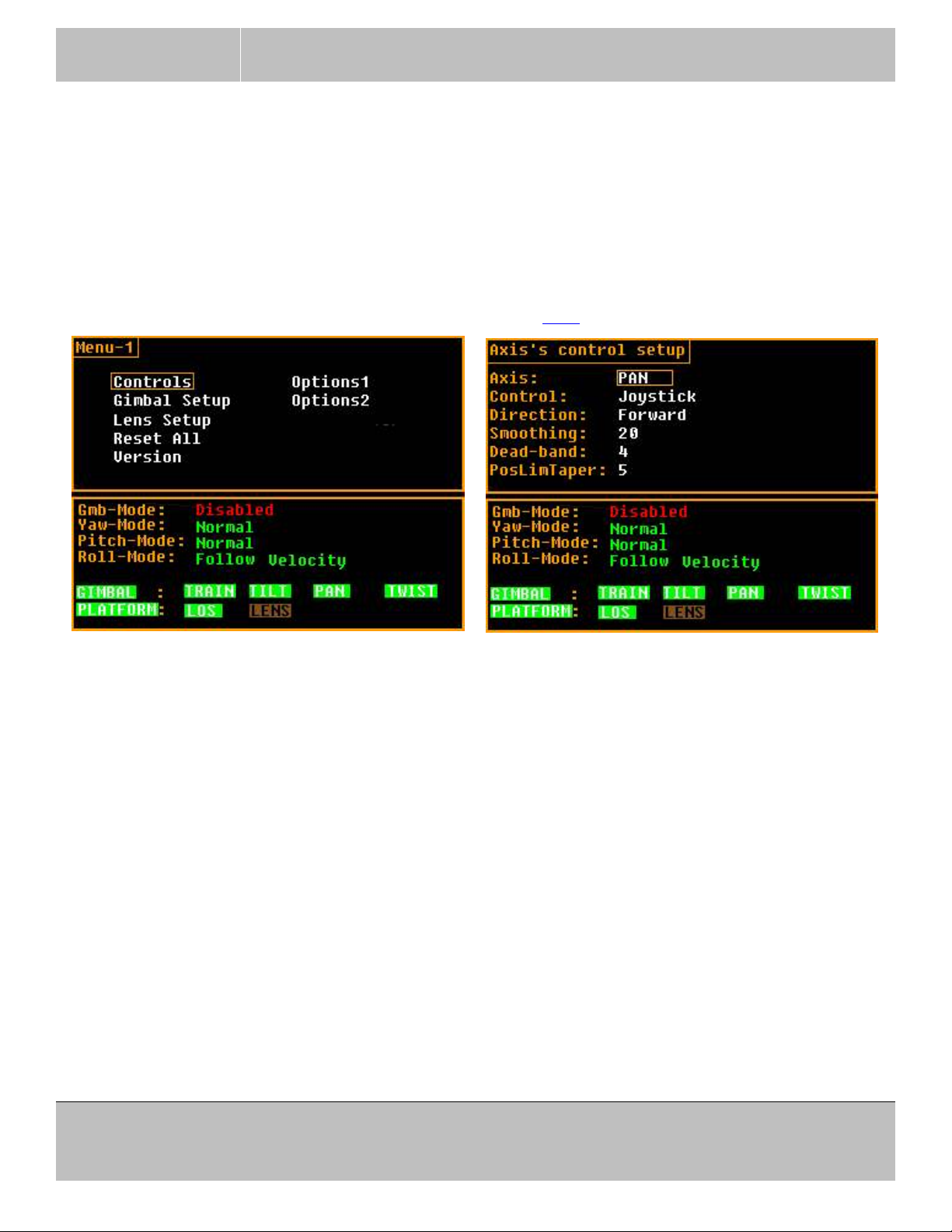
To change control parameters, press MENU and select (¶ 3.2.2) “Controls”.
MAXIMUS 7 OPERATOR’S MANUAL
August 17, 2016
Select the desired axis in the first line, then select the control device.
Direction. Set for each individual device on each axis.
Smoothing. Set for each individual device on each axis.
For joysticks recommending 10 or higher.
For wheels recommending 1 for fast response.
For pan-bar recommending minimum smoothing of about 10 otherwise you may see “stepping”.
Dead-band. Set for each individual device on each axis.
For joysticks recommending more then 4 especially in linear joystick mode.
If experiencing drift from the stick, first NULL the stick by pressing and holding SHIFT then press
NULL. If this does not work well increase dead-band.
Wheels do not need dead-band or very little, recommending minimum.
Pan-bars do not need dead-band or very little, recommending minimum.
31240 La Baya Dr. Ste. A
Westlake Village, CA. 91362
818-889-6060
Page 18 of 74
SPACECAM
SYSTEMS, INC.
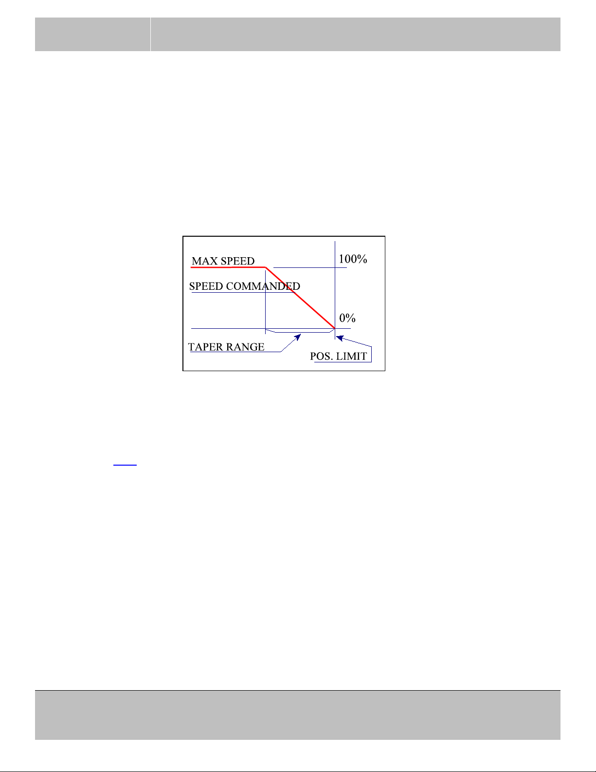
PosLimTaper. Set individually for each axis.
This parameter resides on the gimbal controller therefore can not be displayed or adjusted if the
communication to the gimbal is broken.
The taper is the axis’s maximum speed’s roll down angle in degrees for the position limits. To
avoid hard stops and malfunction of the position limit the velocity is proportionally lowered within
this range from the stop position. The minimum taper value is 2, the maximum is 50 degrees. The
actual command speed is always under the red speed limit. If the taper value is too low and the
camera operator slams the axis into the position limit too fast the inertia may drive the axis through
the limit and the function fails.
MAXIMUS 7 OPERATOR’S MANUAL
August 17, 2016
The last selected device will be the operating device for that axis after leaving the menu. That can be
changed easily on the main screen.
Exit from the setup menu by pressing MENU or BACK.
Select (¶ 3.2.2) control device from main screen:
In the main screen go to desired axis’ control device with the arrow keys.
Set desired operating device.
31240 La Baya Dr. Ste. A
Westlake Village, CA. 91362
818-889-6060
Page 19 of 74
SPACECAM
SYSTEMS, INC.
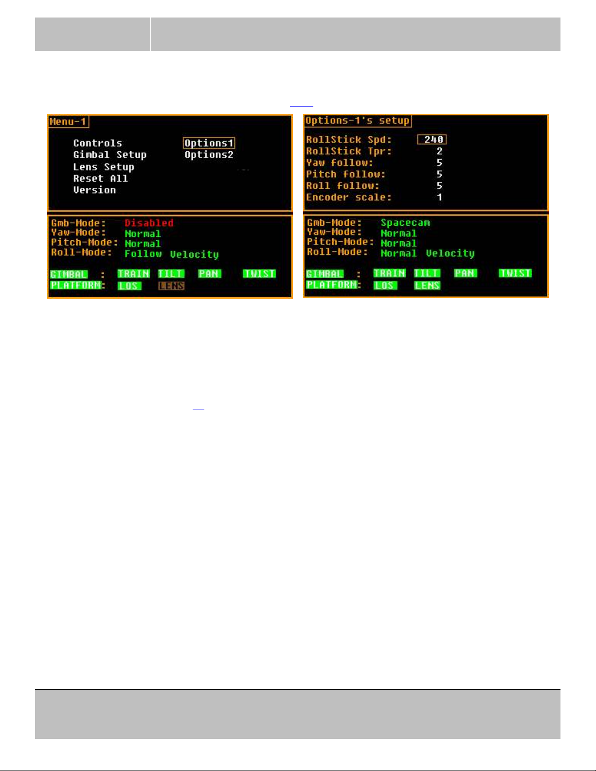
3.2.4 Option-1’s.
To change options, press MENU and select (¶ 3.2.2) “Options”.
MAXIMUS 7 OPERATOR’S MANUAL
August 17, 2016
These parameters reside on the gimbal controller therefore can not be displayed or adjusted if the
communication to the gimbal is broken.
RollStick Spd To change the maximum Speed of the roll in position mode.
RollStick Tpr To change the taper range of the roll in position mode. See explanation of taper range
on page 19.
Yaw follow To change the yaw follow mode filter (follow dynamics), the larger the number
the slower the response.
Pitch follow To change the pitch follow mode filter (follow dynamics), the larger the number
the slower the response.
Roll follow To change the roll follow mode filter (follow dynamics), the larger the number the
slower the response.
Encoder scale To change the pre-scale of the wheel and pan-bar encoders. Range is from 1 to 16. Use
1 or 2 for wheels and 16 for Cartoni pan-bar.
31240 La Baya Dr. Ste. A
Westlake Village, CA. 91362
818-889-6060
Page 20 of 74
SPACECAM
SYSTEMS, INC.
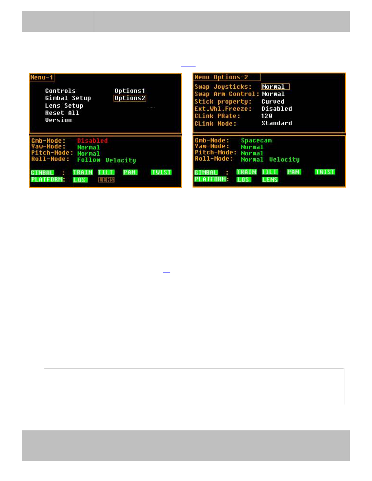
3.2.5 Option-2’s.
To change options, press MENU and select (¶ 3.2.2) “Options”.
MAXIMUS 7 OPERATOR’S MANUAL
August 17, 2016
Swap Joysticks To swap the front panel sticks left to right.
Swap Arm Control
If the analog control devices are used on a panbar the controls can be swapped left to
right if placed correctly. This command is swapping the ANALOG CONTROL1
analog input with ANALOG CONTROL3 and ANALOG CONTROL2 with
ANALOG CONTROL4. Those inputs are available on the ANA connector (in position
of formal BLOOP) and used to control Roll, Zoom, Focus and Iris with analog devices
(POT, Joystick). (page 38 for signals on the connector)
Stick property The sticks (pan, tilt and roll) have a linear (standard) and a curved operating mode. In
standard mode the sticks are a lot more sensitive at the zero position. The curved mode
is the default Spacecam mode.
Ext.Whl.Freeze The external keys connected to the ANA connector can be enabled or disabled here.
The keys can be used to freeze the wheels or pan-bar.
Not all consoles have this connector it is an upgrade.
Not upgraded consoles must have this option disabled.
The following modes were made for tests, do not alter them!
Clink PRate
Use 120!
Toggles the console to gimbal packet rate between 120 and 125 packets per second.
31240 La Baya Dr. Ste. A
Westlake Village, CA. 91362
818-889-6060
Page 21 of 74
SPACECAM
SYSTEMS, INC.
MAXIMUS 7 OPERATOR’S MANUAL
August 17, 2016
Clink Mode
Use “Standard” mode!
Toggles between Standard and UniDir console-gimbal communication modes. In
UniDir mode the console does not expect packets from the gimbal but still operates.
If the status packet does not arrive from the gimbal a lot of functions won’t work.
No parameters should be changed in this mode, the position limit won’t work. Etc...
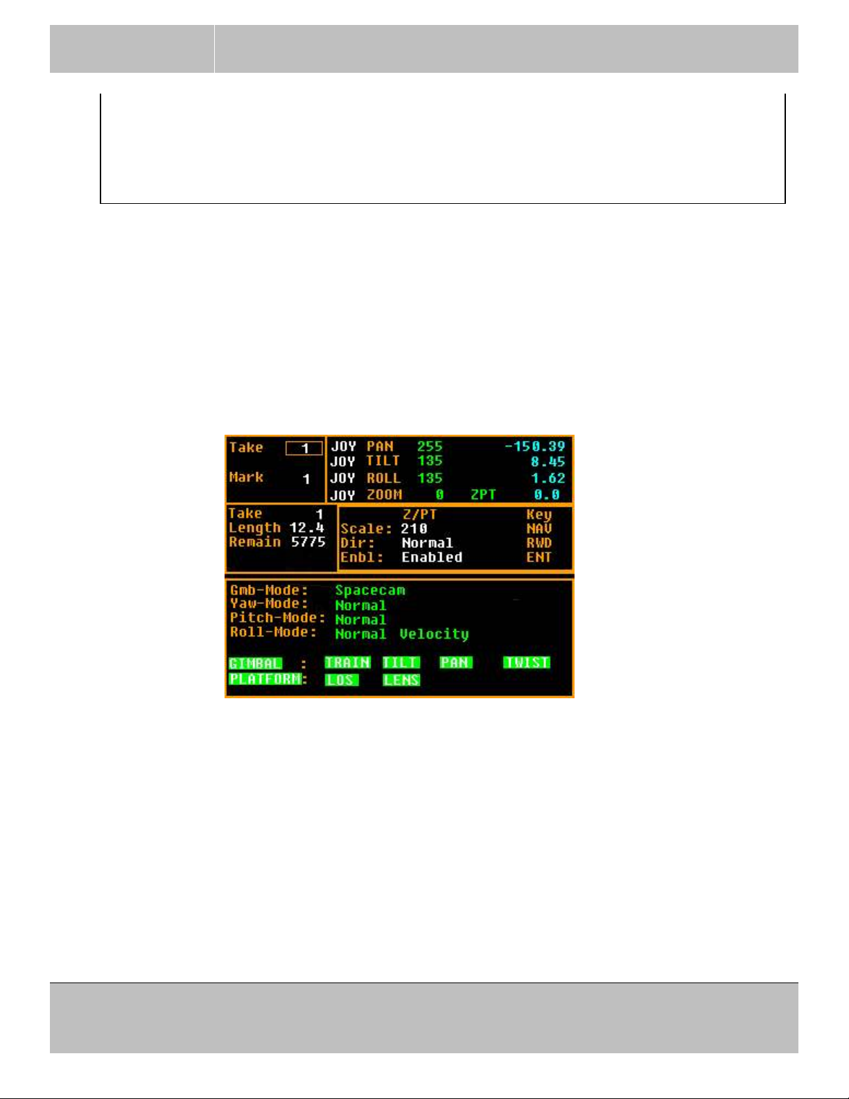
3.2.6 Zoom auto Pan-Tilt sense control.
Not all functions will work with this window displayed, do not leave it on after finished setting up!
The “Z/PT SENSE” key toggles the window.
This function will desensitize the pan and tilt control when the zoom is at the long end. The zoom control
must be setup and work for this function to operate properly.
Press the “Z/PT SENSE” key in the CTRL SCALING group on the front panel. The setup window will be
displayed and the zoom can be operated to help find the required scaling factor.
Press the arrow keys to increase or decrease the scaling. 240 is the maximum and performs most
effectively. 0 scaling is the minimum and has no effect. Press the left arrow to go to 80 and the right arrow
to got 160. Press the SHIFT concurrently with the up/down arrow to step by 10-s.
Press the RWD key to set the direction of the zoom control. The zoom position command ranges from 0 to
655. On most lenses 655 is the long end. Select Normal when 655 is the long end.
Press ENT or the Center Nav key to toggle enable-disable of the function. When the Z/PT is enabled a
green “ZPT” is displayed in the axis status window’s zoom row.
Press the “Z/PT SENSE” key to exit the setup window.
31240 La Baya Dr. Ste. A
Page 22 of 74
Westlake Village, CA. 91362
818-889-6060
SPACECAM
SYSTEMS, INC.
MAXIMUS 7 OPERATOR’S MANUAL
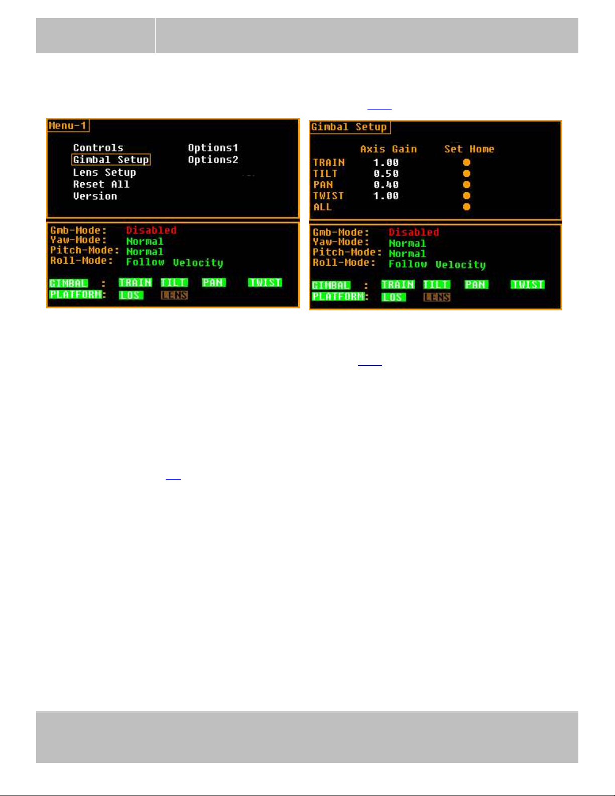
3.2.7 Gimbal Setup.
To change some gimbal parameters, press MENU and select (¶ 3.2.2) “Gimbal Setup”.
August 17, 2016
Setting axes’ Master Gains
The first column sets individual axes Master Gains. Select (¶ 3.2.2) one of the gains to change it. Press
SHIFT concurrently to step by 0.1. The gain values are immediately saved in the active RAM and in the
nonvolatile memory at each key press! There is no cancel function.
The system master gain is adjusted with the F4 key on the main screen, not on this setup screen.
Setting axes’ Home Positions
The home position (P 4.4) is where the axis position shows ZERO. This can not be anywhere! Incorrect
home position will cause major malfunction of the gimbal!
Preferred method is with the maintenance program from a PC.
To set home position for each axis, move the axis to the required position manually (gimbal disabled),
move the focus to a button that belongs to the desired axis and press ENT.
Lower the system gain to test!
31240 La Baya Dr. Ste. A
Westlake Village, CA. 91362
818-889-6060
Page 23 of 74
 Loading...