

Page 1
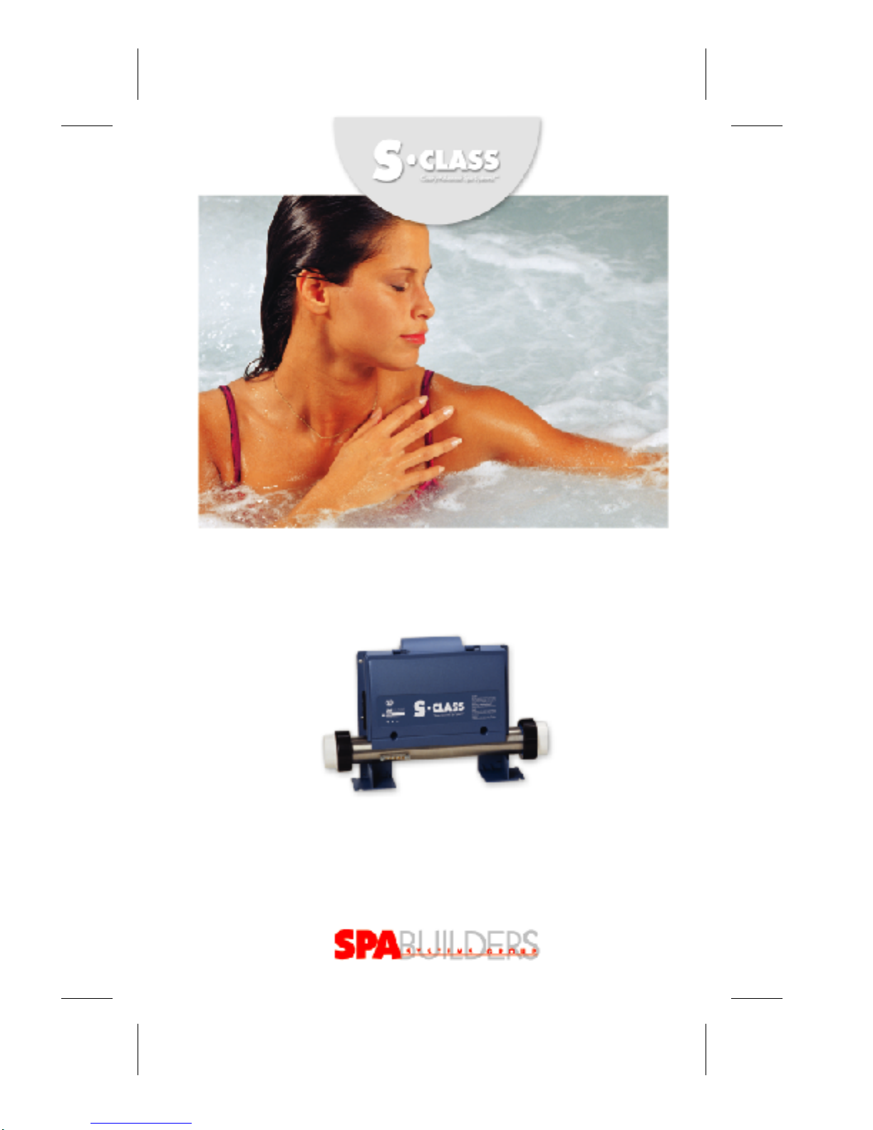
CLEARL Y ADVANCED SP A SYSTEMS!
OWNER'S MANUAL
SC-CF-SBD SPA SYSTEMS
INST ALLA TION, INSTRUCTIONS & MORE!
™
TAKING OVER THE WA VES!
Page 2

Contents
Topics covered in this manual are as follows:
Warnings Warning instructions 3
General Information Safety instructions 7
Specifications General specifications 9
Electrical & temperature specifications 10
Keypad dimensions 11
Power box dimensions 12
Installation Keypads
• K-18 13
• K-19 14
Overlays 15
Power box 17
Connecting
• your pack to your spa 18
• keypad & probe 19
Optional wet-end fitting 20
Jumpers Jumper selection 21
Configuration Output connectors 23
Pump 1 24
Blower 26
Pump 2 / blower 27
Ozonator 28
Electrical wiring 29
Powering your pack
• with strain relief 30
• with conduit adaptor 31
Instructions Single pump system 33
Dual pump or pump & blower systems 36
Alarms 40
Error conditions 41
Miscellaneous Wiring diagram 43
Factory default settings 44
Page 3

Notes:
SC-CF-SBD Owner’s Manual2
Page 4
Warnings
Important Warning Instructions
• The temperature sensor must be installed in order to read
the water temperature properly. Improper installation of
the sensor can cause overheating or insufficient heating of
the water. The spa manufacturer must verify if the
temperature measured by the sensor is the same as the
actual water temperature and that the sensor cannot be
affected by external conditions (ex: air temperature).
• This control is not suitable and cannot be used for gas
heater applications.
• This control must always be connected to a circuit
protected by a ground fault interrupter.
• Install the control on a solid surface to minimize mechanical
vibrations.
• The power input cable should always be secured in place
with a proper strain relief.
• A notice should be installed by the manufacturer on the
finished product to notify the end user to always check the
water temperature with his hand before entering the water
so as to prevent burns and other injuries which may result
from improper water temperatures.
• This control should not be installed in the proximity of
highly flammable materials.
• This control is not protected against water infiltration. It
should not be installed in a location or in a manner which
could lead to contact with water.
• The electrical load of connections to this control must not
exceed the ratings specified by Spa Builders Systems Group
Inc. Failure to ensure compliance with proper electrical load
specifications may cause hazardous operating conditions
and/or decreased the life span of the control.
3SC-CF-SBD Owner’s Manual
Page 5
Warnings
Important Warning Instructions
• Use copper wiring only.
• This control is certified as a component only. The finished
product which will incorporate this control should be
certified by the proper agency as a finished product. In no
circumstances should the fact that the control is certified as
component be considered sufficient for the finished product
to comply with certification requirements. The manufacturer
is solely responsible for ensuring that the finished product
complies with all applicable laws and regulations.
• Ambient air temperature in the vicinity of the control
location should not exceed the maximum temperature
rating specified by Spa Builders Systems Group Inc.
• The spa elements, containing water exposed to cold air
(piping, pumps, valves, etc.) must be approximately at the
same ambient temperature as the power module of the
control to prevent adequately from water freezing.
• This control should be serviced by qualify personnel only.
• If a fuse must be replaced, it should be replaced only with a
fuse of the same type and rating.
• The control must not be altered or modified in any way.
• Do not connect any equipment to this control other than
equipment and or accessories that are specified or approved
by Spa Builders Systems Group Inc. for each output.
• This control should always be installed with the proper orientation as per the specifications provided by Spa Builders
Systems Group Inc.
• Do not create any opening in the control.
• Do not extend temperature sensor cables.
SC-CF-SBD Owner’s Manual4
Page 6
Warnings
Important Warning Instructions
• This control must be installed as specified in the Spa
Builders Systems Group Inc. product certification report.
• It is possible that an output fail in the "on" position.
Make sure that this cannot create any hazard.
• The spa must comply with the ‘kinetic heating test’
described in UL1563 standard section 47.2.: "While at the
maximum water temperature from the water temperature
test described in 46.1, a unit, covered as specified in 47.2.2,
shall be operated circulating water at the maximum flow
rate without the heater operating until thermal equilibrium
as defined in 45.8 is attained or until ultimate results occur.
Any blower shall not be operating and any air induction
control shall be closed. A blower that heats the water, if
provided, shall be operated. The results are acceptable if
the water at any tub inlet does not exceed 50°C (122°F)".
• Any ventilation openings on the pack must be free from
obstructions that could limit the ventilation flow rate.
• The user manual must specify that if the keypad is physically
damaged, the end user must not use the finished product
and the keypad should be replaced immediately.
• Do not submerge the temperature probe completely in
water. Only the stainless steel portion should be in contact
with water.
• This product is provided with a pre-calibrated pressure
switch. Make sure that the pressure switch setting is
adequate for your application.
• Should you have any questions with respect to any of the
foregoing or the reference materials mentioned herein,
please do not hesitate to contact us.
5SC-CF-SBD Owner’s Manual
Page 7

Notes:
SC-CF-SBD Owner’s Manual6
Page 8

General Information
Important Safety Instructions
This manual
Caution
Electrical Hazard
Notice
Important
Congratulations! You have purchased one of the finest spa
packs available. Take the time to carefully read these
instructions.
Low voltage or improper wiring may cause damage to this
control system. Read and follow all wiring instructions when
connecting to power supply.
This pack contains no user serviceable parts.
Contact an authorized service center for service.
All connections must be made by a qualified electrician in
accordance with the National Electrical Code and any state,
province or local electrical codes in effect at the time of the
installation.
RISK OF ELECTRICAL SHOCK!
If used with 120V, your pack must be connected only to a
grounded receptacle.
7SC-CF-SBD Owner’s Manual
Page 9

Notes:
SC-CF-SBD Owner’s Manual8
Page 10

Specifications
General Specifications
Description
Features
From keypad
These packs are perfect for spas with one or two pumps (or
one pump and a blower), a heater, an ozone generator and
a mood light.
• Automatic time-out on all outputs
• 3 digit LED display
• Digital temperature display
• Sensor failure detection
• Programmable filtering cycles
• High-Limit protection
• Pressure switch failure detection
• Current limiting option
• Freeze protection
• Temperature measurement within ± 1°F
• Temperature set point
• Temperature display in °C or °F
• Spa light control (on/off)
• One or two-speed pump control
9SC-CF-SBD Owner’s Manual
Page 11

Specifications
Electrical Specifications
Input
Outputs
Pump 1
Pump 2
(blower)
Heater
Ozone
Light
240 V, 48 A, 60 Hz
120 V, 15 A, 60 Hz
(high) 120 V, 14 FLA / 80 LRA
(low) 120 V, 14 FLA / 80 LRA or
(high) 240 V, 14 FLA / 80 LRA
(low) 240 V, 14 FLA / 80 LRA
Connector: J&J or AMP
120 V, 14 FLA / 80 LRA or
240 V, 14 FLA / 80 LRA
Connector: J&J or AMP
120 V, 8.3 A or
240 V, 16.7 A
120V. 3A or
240 V, 3A
Connector: J&J or AMP
12 V, 1 A
Connector: Direct lamp socket assembly
Temperature Specifications
Operating
Storage
Humidity
Set Point Adj.
Temp. Measure
0 122°F
-17 50°C
-40 160°F
-40 70°C
Up to 80% non-condensing
Adjusted in 1° increments from 59° to 104°F (10° to 40°C)
Better than 1°F
Page 12
K-18
Specifications
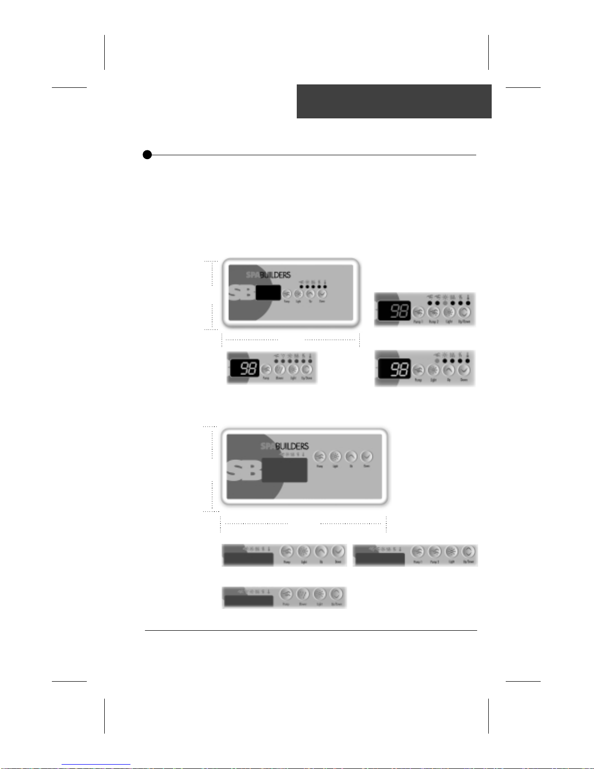
Keypad Dimensions
All keypads have been sealed to perfection to insure years of
trouble-free usage. The extent of their design demonstrates a
clear commitment to excellence in quality and reliability. Two
models of keypads are available: K-18 & K-19. Both models
include specific overlays for single pump and dual pump
systems or single pump and blower systems.
2
1/2
"
K-19
5"
Single pump with blower system
4
1/4
"
7"
Single pump system Dual pump system
Single pump with blower system
Dual pump system
Single pump system
11SC-CF-SBD Owner’s Manual
Page 13
Specifications
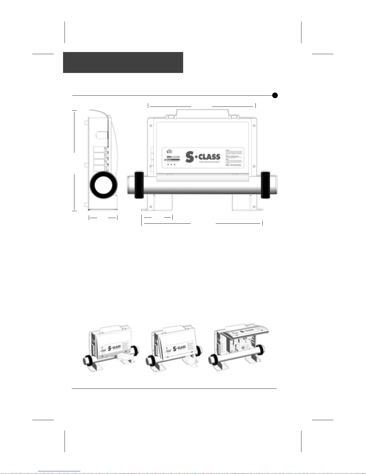
P ower Box Dimensions
11 1/2"
mm
292
12 13/16"
325
mm
Power Box
Hinged Cover
3 3/8"
86
3 1/2"
mm
mm
89
14 1/4"
362
mm
The design of your pack power box took size, weight and
ease of installation into account. Compact and light, the
power box of your pack is made of thick plastic and is highly
resistant to shock, corrosion, chemicals and humidity.
The cover of the power box can be easily opened to access
the connection ports. Simply remove the 2 front cover
screws and pull the hinged cover up to access main board,
connectors and jumpers.
SC-CF-SBD Owner’s Manual12
Page 14
Installation
Main Spa Side Control (K-18)
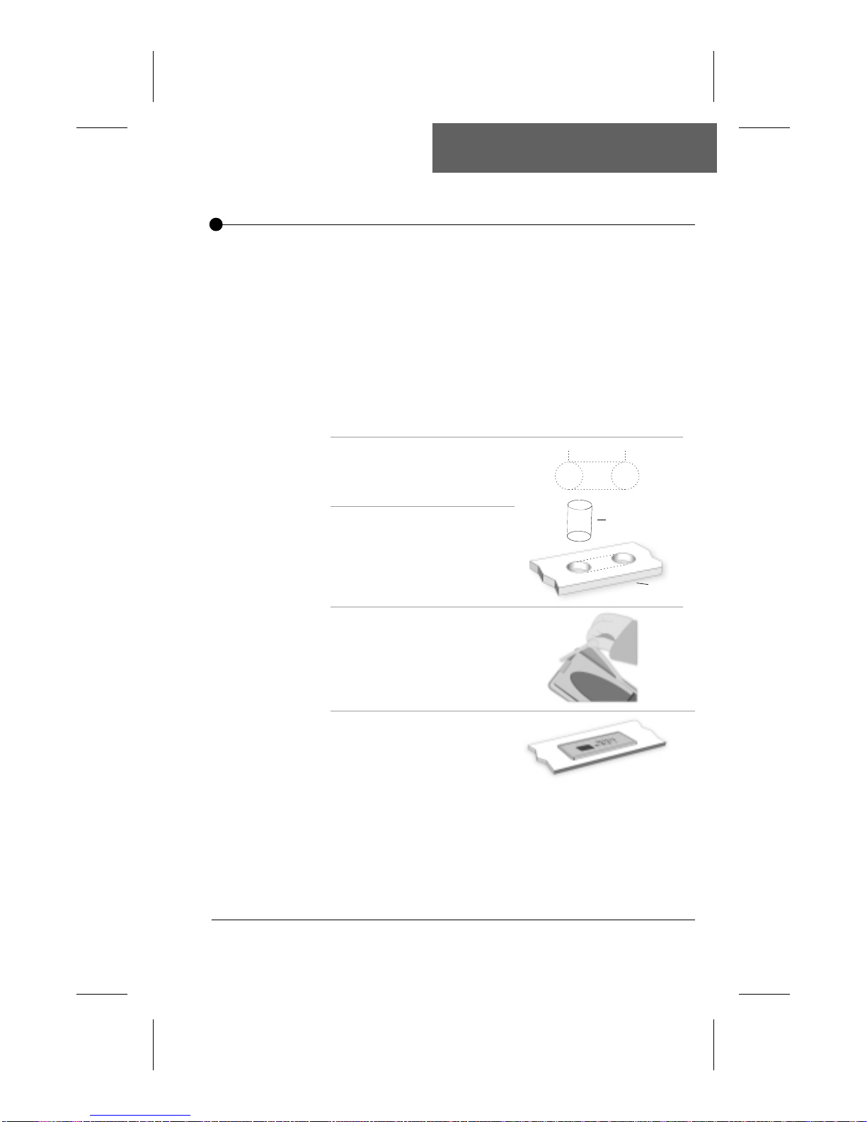
Installation
Mounting System
The first step in the installation procedure of the K-18 main spa side
control is to cut a hole directly on the edge of the spa.
The hole must be a 1" by 3
5/8 " rectangle to allow the keypad box
to slide into position.
The keypad should be installed directly on the spa (or very close)
for it to be easily reached by the user.
Steps to follow:
2 5/8"
66
1- Select the appropriate
location for the
mm
1" dia
25.4
mm
1" dia
25.4
mm
control unit.
2- Drill two 1” holes as
1" dia. drill
shown in figure 2. Cut
the material between
the two holes.
Bath Edge
3- Peel off the double-
faced tape protective
layer.
Note: If the keypad is physically damaged, the spa must not be used and the
keypad should be replaced immediately.
4- Insert the keypad and
secure it in place by
pressing firmly on
the keypad.
13SC-CF-SBD Owner’s Manual
Page 15
Installation
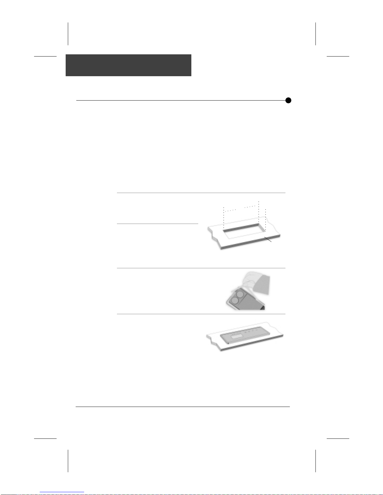
Main Spa Side Control (K-19)
Installation
Mounting System
The first step in the installation procedure of the K-19 main spa side
control is to cut a hole directly on the edge of the spa.
The hole must be a 2
5/8
" by 6
3/8
" rectangle to allow the keypad box
to slide into position.
The keypad should be installed directly on the spa (or very close) for it
to be easily reached by the user.
Steps to follow:
1- Select the appropriate
location for the control unit.
2- Cut a 2
5/8
" by 6
3/8
rectangle on the edge of the
spa.
3/8
"
6
"
5/8
"
2
Spa Side
3- Peel off the double-faced
tape protective layer.
4- Insert the keypad and secure
Note: If the keypad is physically damaged, the spa must not be used and the
keypad should be replaced immediately.
it in place by pressing firmly
on the keypad.
SC-CF-SBD Owner’s Manual14
Page 16
Installation
Overlays
Note:
Installation
Please note that the following installation procedure is similar
for K-18 and K-19 pack overlays.
Make sure to select the overlay that goes with your spa
configuration.
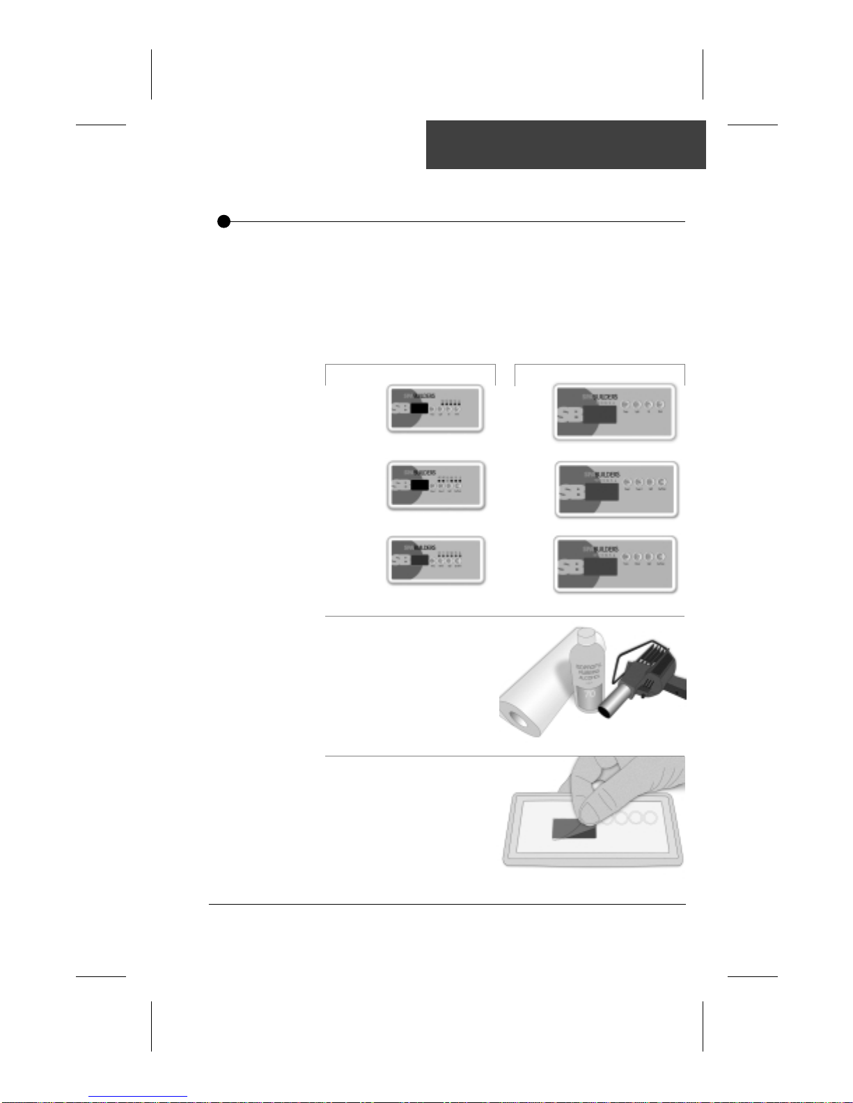
K-18 overlays
Single pump system
Dual pump systems
Pump & Blower systems
K-19 overlays
Single pump system
Dual pump systems
Pump & Blower systems
To properly install an overlay
on a keypad, you only need a
hair dryer, paper towel and
rubbing alcohol.
First, peel off the plastic film
that protects the LED display
window .
15SC-CF-SBD Owner’s Manual
Page 17
Installation
Overlays
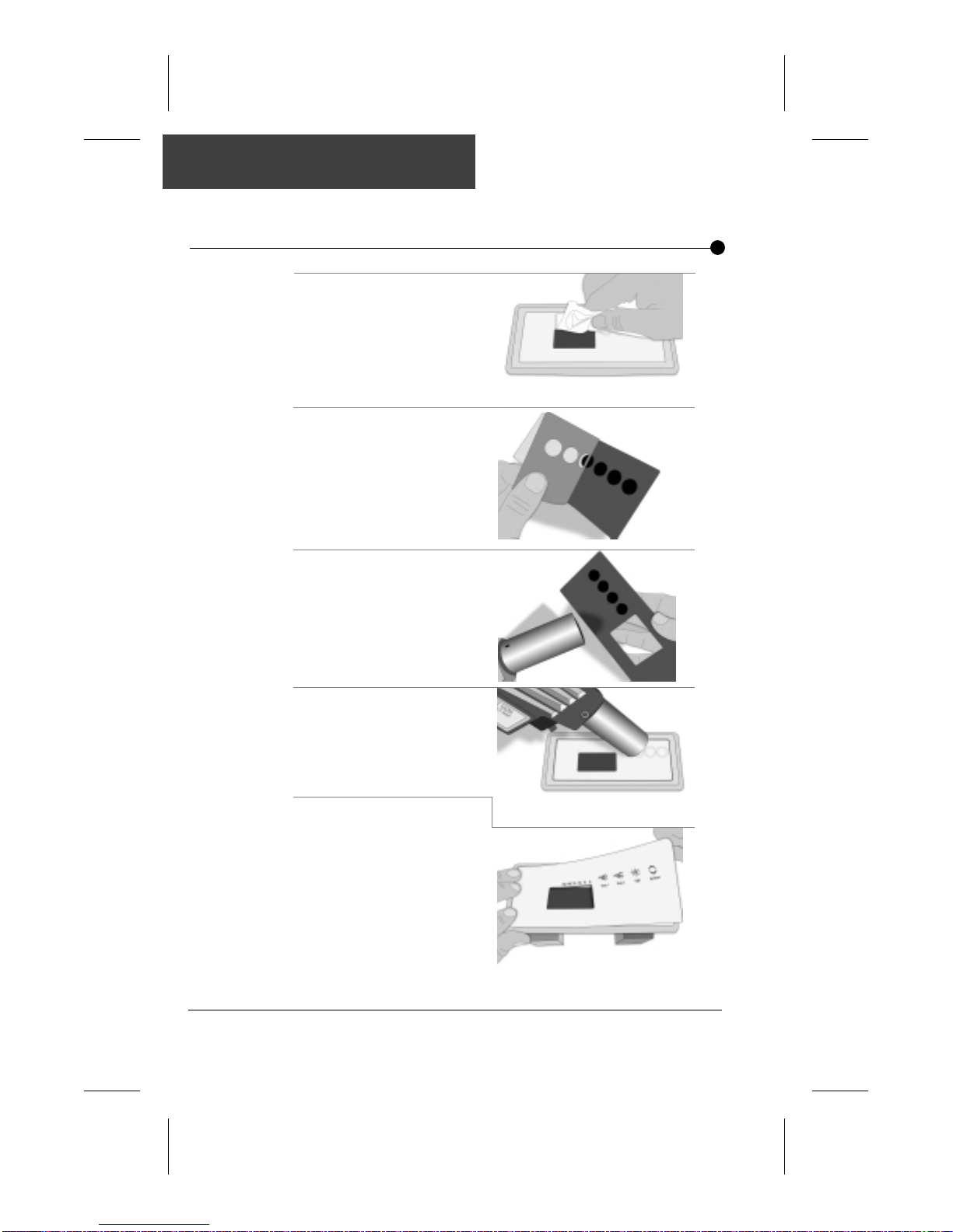
Clean the surface of the
keypad with an alcohol
saturated paper towel.
Peel the protective paper
from the overlay.
Gently heat the back of the
overlay with the hair dryer.
Heat the surface of the
keypad.
Place the overlay on the
keypad starting with its left side.
Make sure the overlay is well
aligned and rests perfectly in
the recess of the keypad.
Insure that the overlay is
properly glued by pressing
with your finger over the
entire surface.
SC-CF-SBD Owner’s Manual16
Page 18
Installation
P ower Box
Power Box
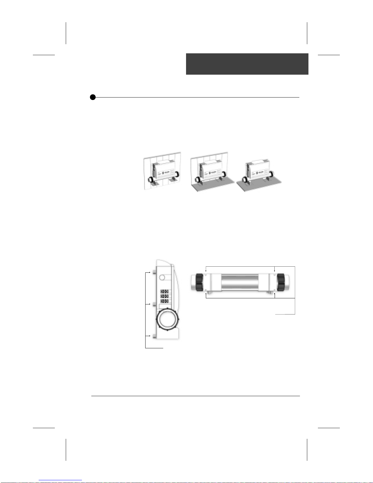
The power box must be installed close to the spa side,
preferably under the spa, at a location where possibility of
water leaks is minimal.
It can be wall-mounted or installed directly on the floor
(or both at the same time).
Six holes on the back of your pack are provided to mount the
pack on a wall.
Four holes located on the pack feet can be used to fix it to the
floor.
Bottom viewFront view
Holes for floor-mounting
Holes for wall-mounting
Warning: Any physical damage to the enclosure arising from misuse,
abuse or improper installation will automatically void any liability of the
product.
17SC-CF-SBD Owner’s Manual
Page 19
Installation
Connecting your pack
Connect to Spa
Plumbing
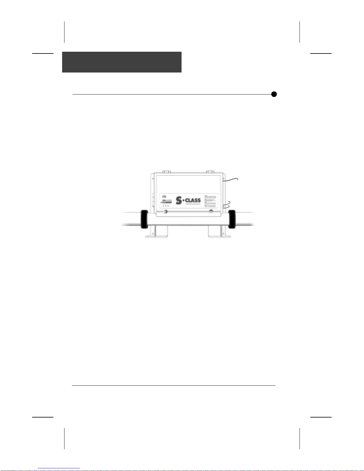
Your pack must be connected to your spa plumbing. The
connections must be made with the tail pieces at both ends of
the pack's heater and must be perfectly sealed.
Refer to your spa manual for more information on how to
properly seal your plumbing connections.
SC-CF-SBD Owner’s Manual18
Page 20
Installation
Main Spa Side Control and Temperature Probes
Connecting to the
Power Box
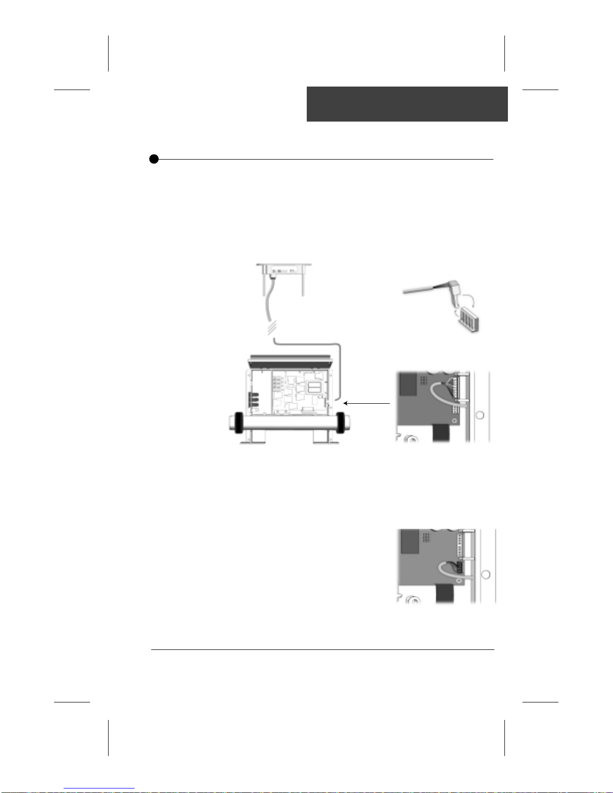
The main spa side keypad must be connected to the standard
side panel port of the control box.
A cable is provided to connect the keypad to the power box.
Attach the connector to the power box as shown.
Keypad
Power Box
Keypad
Cable
Proper Way to Connect Keypad to
Standard Side Panel Port
Cable facing the left
side of the box
Pins slide
into the cable head
Header
Warning
Connecting the
Temperature
Probe
Clearance between Low and High Voltage conductors must be at
least 1/4".
The water temperature
probe must be similarly
connected to the power
box, with cable following the
same route as the main
keypad.
19SC-CF-SBD Owner’s Manual
Page 21
Installation
Optional W et-End Fitting
Optional
Wet-End Fitting
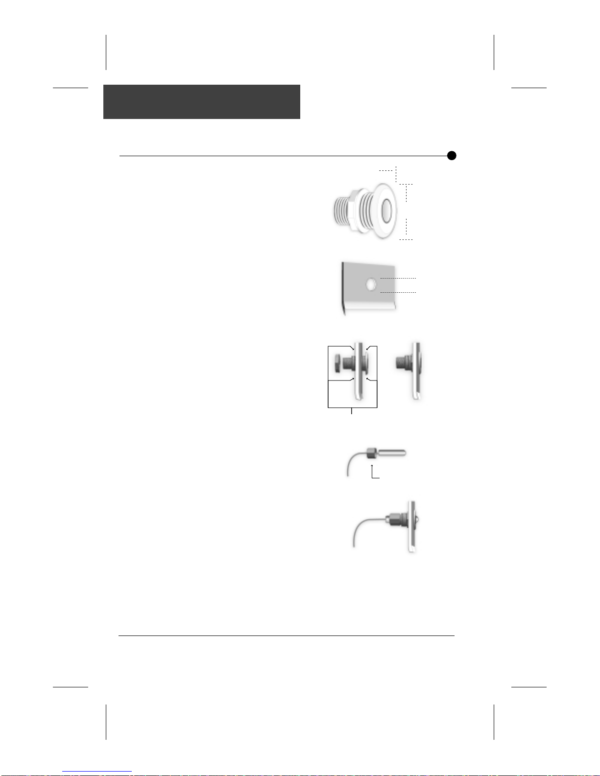
The optional wet-end fitting
secures your pack
temperature sensor into
position in the spa.
1
1/2
"
5/8
"
1
To install
the fitting
To install
the sensor
1) Select a location for the
temperature sensor. It
should be below water
level, accessible and as
close as possible to the
pack.
2) Drill a 1" diameter hole
in the spa wall.
3) Install the fitting as
shown. It should be
tight enough to
prevent water leaks.
Do not forget to apply
silicone.
1) Slide the temperature
sensor inside the
stopper nut of the
wet-end fitting.
2) Insert the sensor into
the fitting. Fully insert the
sensor into the wet-end
fitting until the tip of the
sensor slightly intrudes
into the spa
1"
Apply silicone
Stopper nut
3) Tighten the stopper nut to ensure proper sealing.
4) Apply foam on the back of the fitting to prevent cold or
warm air from affecting the sensor reading.
SC-CF-SBD Owner’s Manual20
Page 22
Jumper s
Jumper Selection
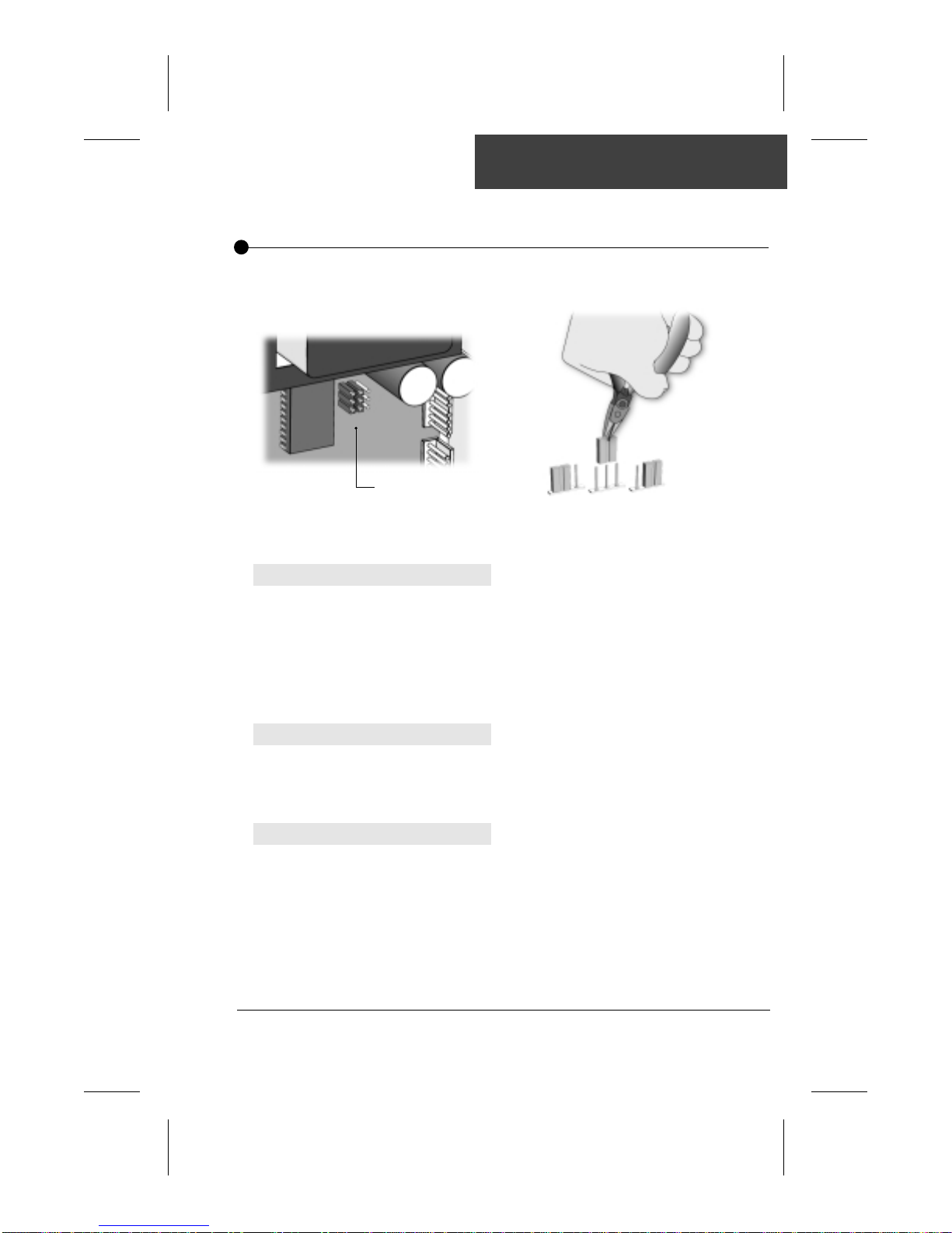
It is possible to change some parameters of your pack by positioning specific
jumpers located on the board. To access the jumpers, remove the 2 front
cover screws then lift the cover of your pack power box.
Position 2Position 1
Jumpers
1• The jumpers are located
on the lower right section
of the board.
Jumper 1: Current Limiting Option
J
umper 1 is used to limit the current drawn when 2 pumps or a pump and
a blower are used.
2• To change a setting, simply pull
the jumper out and reinsert it in
the desired position.
Position 1 (HC): All outputs can be turned on at the same time.
Position 2 (LC)*: The system will not turn the heater on when one
*Mandatory for 120 vac systems
pump (or blower) is in high speed. The "Heater" icon
will flash on the display to tell the user that there is a
call for heat but the heater is not allowed to start.
Jumper 2: Temperature Unit
This jumper is used to select the temperature unit.
Position 1: Temperature will be displayed in Fahrenheit degrees.
Position 2: Temperature will be displayed in Celsius degrees.
Jumper 3: Pumps
Position 1: Single pump (single pump K-18 or K-19 overlays)
Position 2: Dual pump or single pump and a blower
Note: It is mandatory that the topside overlay matches
(dual pump system K-18 or K-19 overlays)
the settings of this jumper
21SC-CF-SBD Owner’s Manual
Page 23

Notes:
SC-CF-SBD Owner’s Manual22
Page 24
Output connections
J&J or Amp connectors
Connecting the
equipment
Pump 1
Pump 2/blowerPump 2/blower
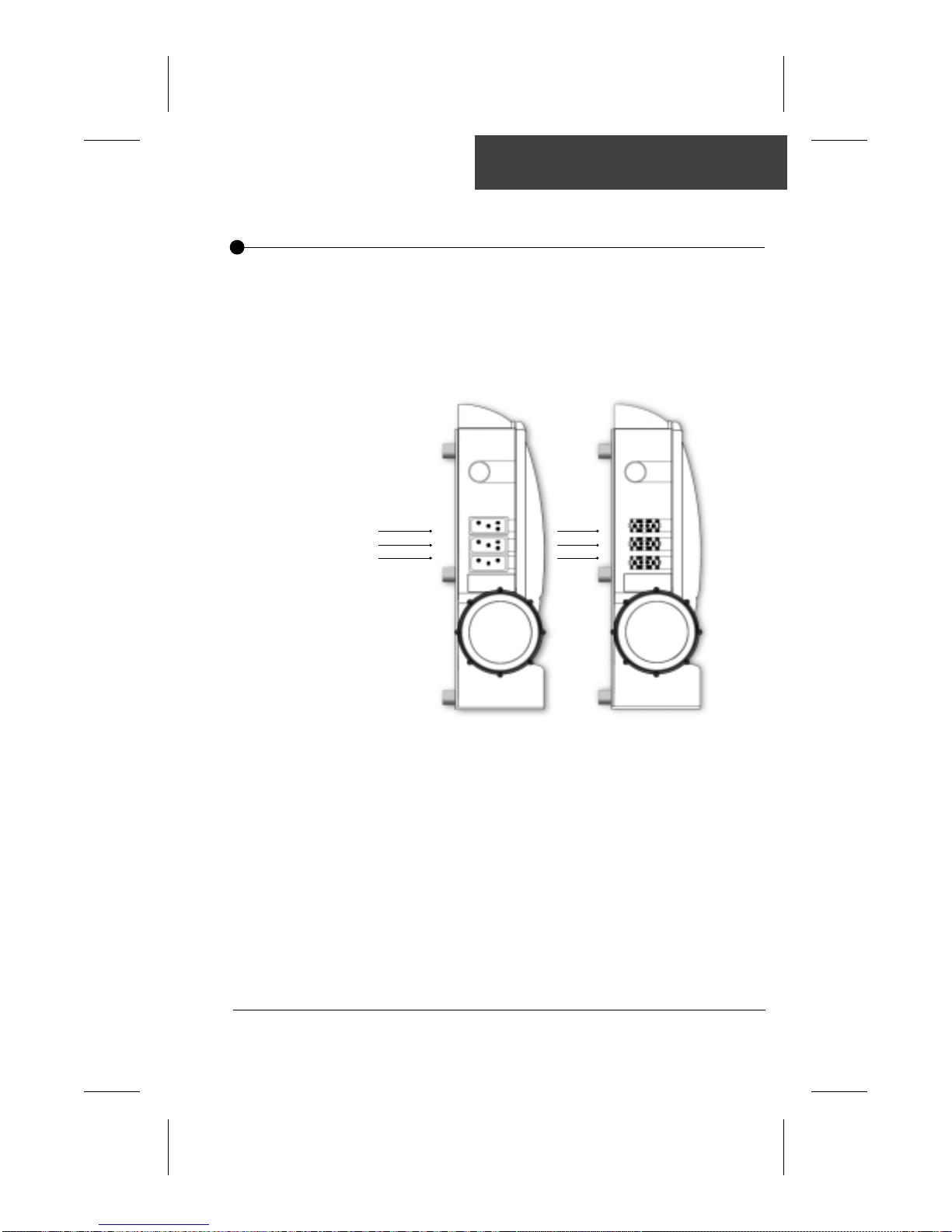
The pumps, blower and ozonator must be connected to
their respective connectors on the side of the pack.
Your pack also comes with a light socket that is ready to
receive a lamp.
Pump 1
Ozone
Pack with
J&J connectors
Pack with
Amp connectors
23SC-CF-SBD Owner’s Manual
Page 25
Output Configuration
Pump 1
Configuration
of Pump 1
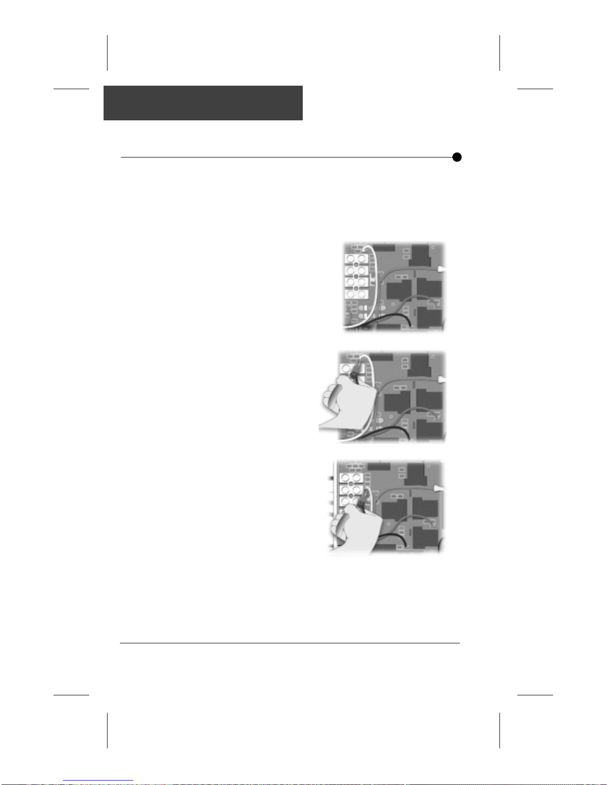
Pump 1 is configured at the factory as a 120 V pump.
If you are using a 240 V pump, you must change the wiring
configuration. Perform the following steps:
1) Locate the pump 1
connectors.
2) Using a pair of long-nose
pliers, unplug the white
wire of the pump 1
connector from the
board. (P7)
3) Reconnect the white
wire to the P18 (connector) and make sure the
connector is properly
inserted.
SC-CF-SBD Owner’s Manual24
Page 26
Output Configuration
Pump 1
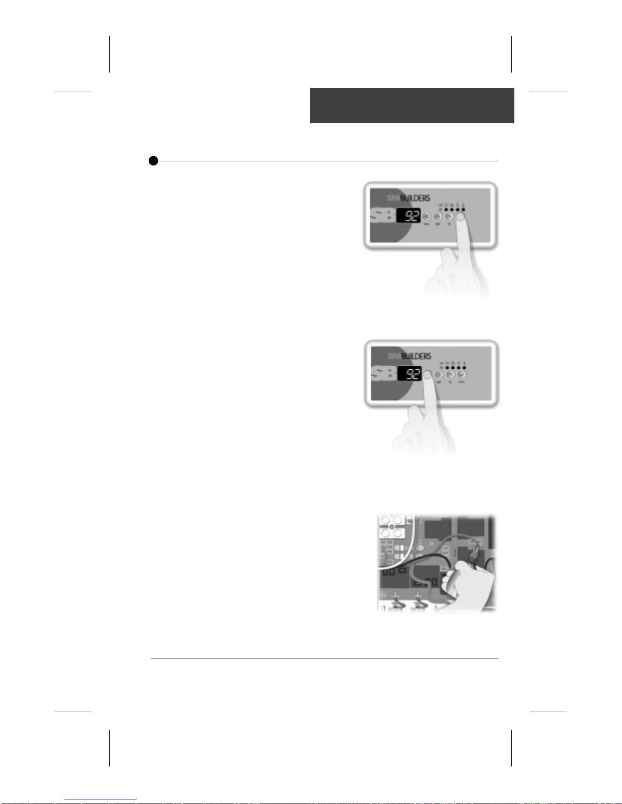
Important Note:
Unfortunately, there are two
different color standards for
two-speed pump wires.
Some use the red wire for
the high speed winding and
others use the black wire.
It is important to have the
proper wiring configuration.
You can only test it when
the system is ready to use.
To do so, lower the set
point below the water temperature to turn the pump
off (it will take 30 secs. for
the pump to go off). Press
Pump 1 key to manually turn
on the pump. It should start
in low speed and not high
speed. If the pump starts in
high speed, follow this
procedure to correct the
problem.
Lower set point
Turn pump on
1) Turn the breaker off.
2) Locate the Pump 1
connectors.
(P12 and P14)
3) Using a pair of longnose pliers, invert the
connection of the black
and red wires. Make
sure the connectors are
properly inserted.
25SC-CF-SBD Owner’s Manual
Page 27
Output Configuration
Blower
Configuration of
the blower
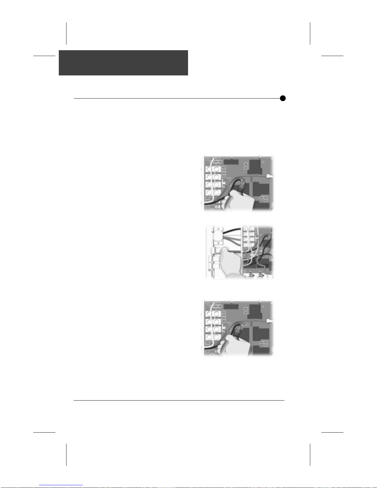
If you purchased a pack with J & J connectors and your spa is
equipped with a blower, you need to replace the factory
installed J&J pump 2 connector with the supplied J&J blower
connector.
To do so:
1) Locate the Pump 2
connectors.
(P6, P11 & P9 for a 120V pump)
(P6, P11 & P17 for a 240V pump)
2) Using a pair of long-nose
pliers, unplug all three
wires from the connectors
on the board.
3) Remove the J&J Pump 2
connector by sliding it from
its slot on the pack.
4) Put the J&J Blower
connector (included with
your pack) in place and
slide the wire through the
hole of the interior panel.
5) Reconnect the three wires
on the board at the following locations
Black= P11
Green= P6
White= P9 for a 120V
blower
P17 for a 240V
blower
Make sure they are properly inserted.
SC-CF-SBD Owner’s Manual26
Page 28
Output Configuration
Pump 2 / blower
Configuation
of Pump 2 /
Blower
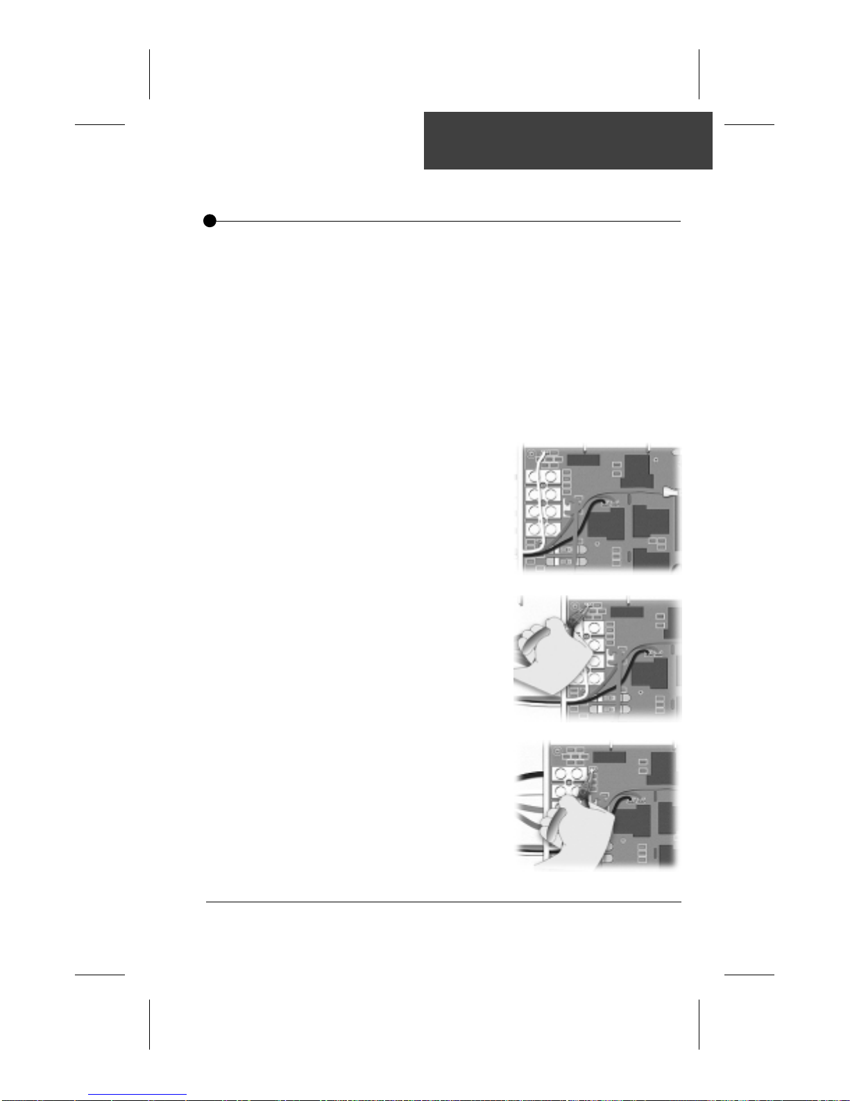
The configuration of Pump 2 (or blower) depends on:
• The pump (or blower) voltage (120V or 240V)
• The power input voltage of the pack
Do not change anything if your pack will be powered with
240V and your Pump 2 (or blower) is a 120V pump
(or blower).
If your pack is powered with 120V and your Pump 2 (or
blower) is 120V, or if your pack is powered with 240V and
your Pump 2 (or blower) is 240V, perform the following
steps:
1) Locate the Pump 2
(or blower) white
wire connector
(P9 for a 120V pump
or Blower)
2) Using a pair of long-nose
pliers, unplug the white
wire of the Pump 2 (or
blower) connector.
3) Reconnect the white wire
to the P17 connector
and make sure the
connector is properly
inserted.
27SC-CF-SBD Owner’s Manual
Page 29
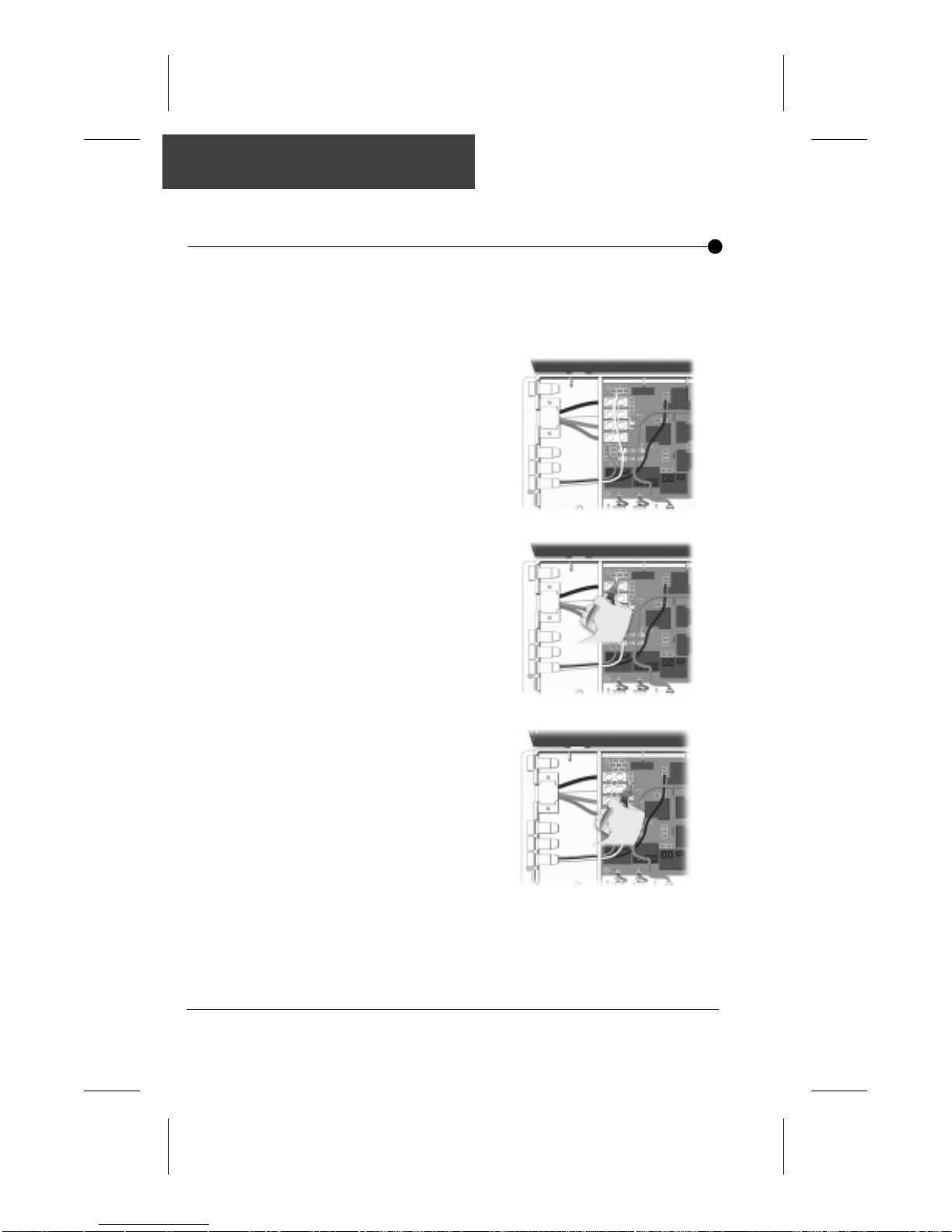
Output Configuration
Ozonator
Configuration of
ozonator output
Your pack is configured at the factory to control a 120V ozonator.
If you want to use a 240V ozonator, you need to change the
white wire connector on the board. To do so:
1) Locate the ozonator
connector.
2) Using a pair of long-nose
pliers, unplug the white
wire of the ozonator
connector (P8) from the
board.
3) Reconnect the white
wire to P19 (see wiring
drawing). Make
sure the connector is
properly inserted.
Note:
The ozonator will be
activated only during
the filter cycle.
SC-CF-SBD Owner’s Manual28
Page 30
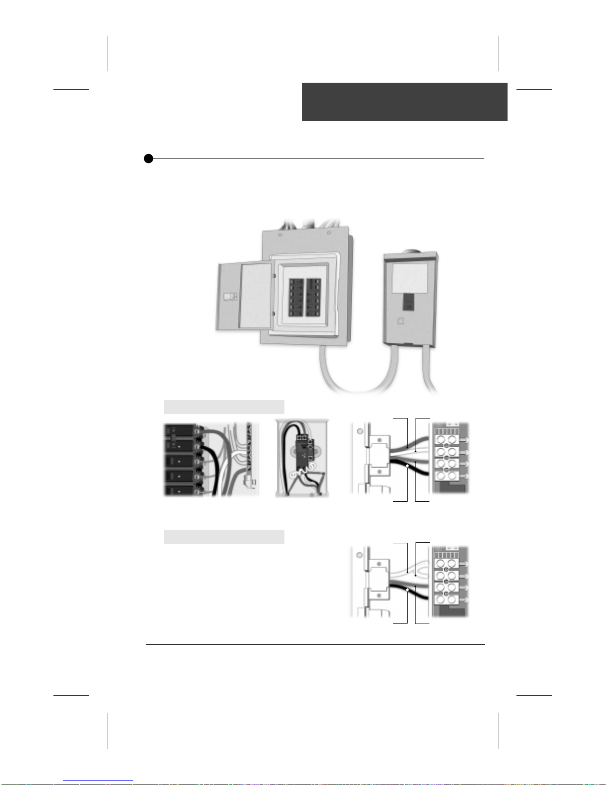
Proper wiring of the electrical service box,
GFCI box and pack terminal block is essential.
• Refer to supplied wiring diagrams.
Connections must be made by a certified electrician
•
Warning: Total current ouput
cannot exceed total current input
rating!
Electrical Wiring
For 240 vac systems:
Electrical Box GFCI
For 120 vac systems:
Red
Black
White
Green
Pack Terminal Block
White
Black
x Jumper supplied with the pack
White x
Green
L2
N
G
L1
L2
N
G
L1
29SC-CF-SBD Owner’s Manual
Page 31
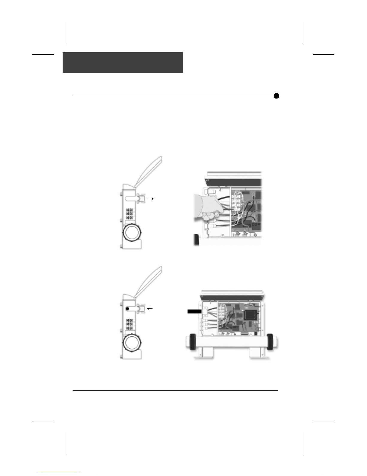
Powering your pac k
With strain relief
Powering the pack
If you are not using a conduit for the power cable:
1) Remove the strain relief.
2) Connect the wires to the terminal block.
3) Install the strain relief and make sure it holds the cable
firmly in place.
12
3
SC-CF-SBD Owner’s Manual30
Page 32
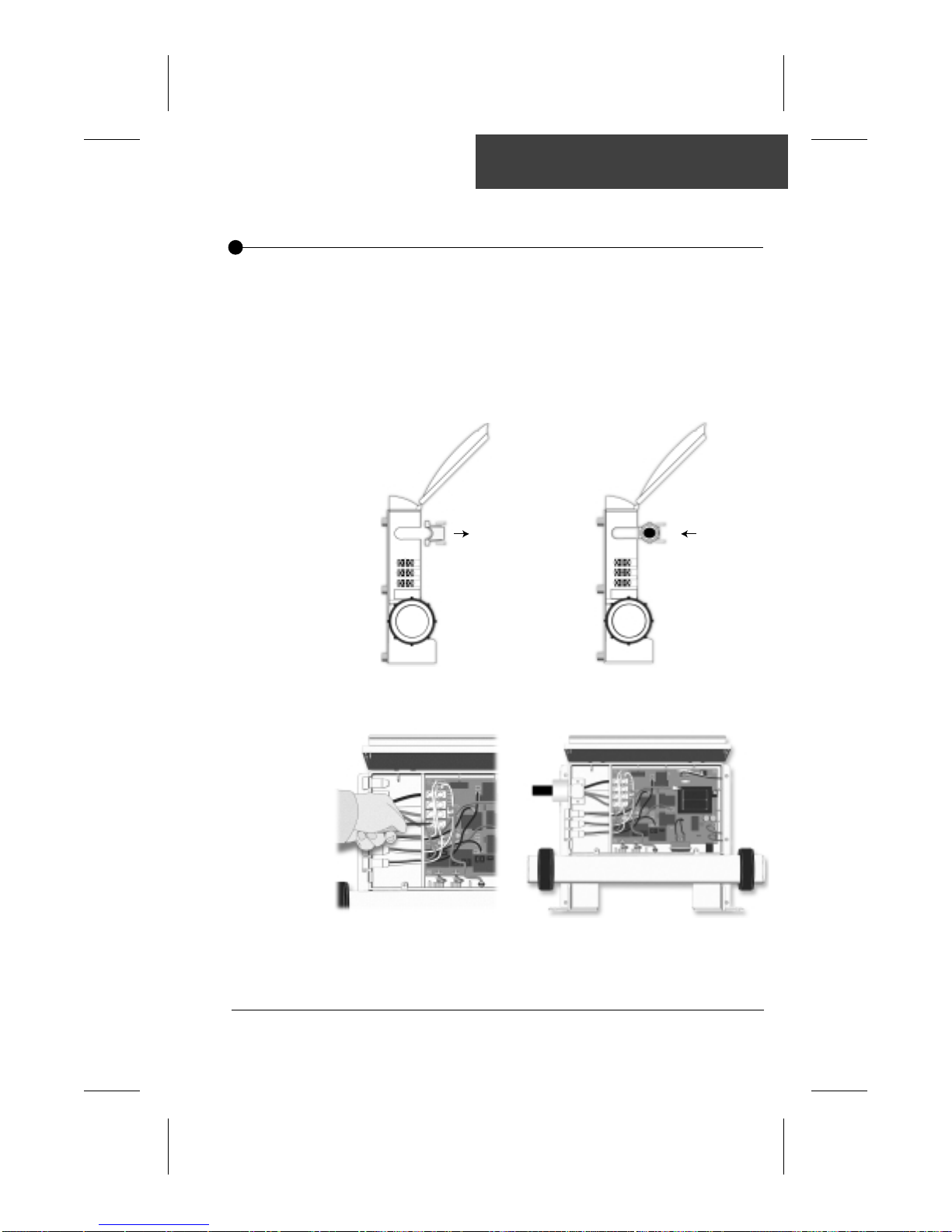
Powering your pac k
With conduit
Powering the pack
If you are using a conduit for the power cable:
1) Remove the strain relief.
2) Install the conduit adaptor.
3) Bring the 4 wires to the pack and connect them to the
terminal block.
1
2
3
31SC-CF-SBD Owner’s Manual
Page 33

Notes:
SC-CF-SBD Owner’s Manual32
Page 34
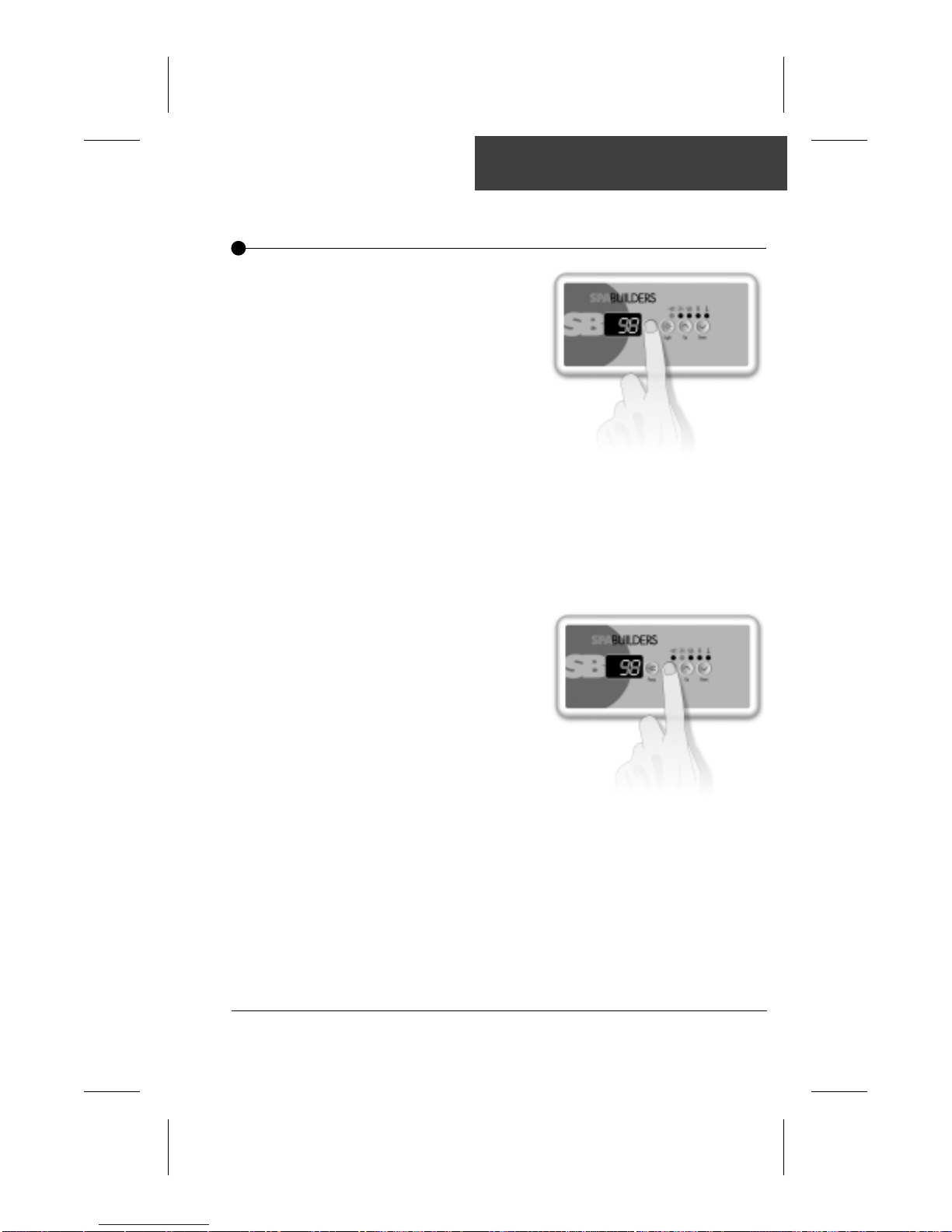
Instructions
Main Spa Side Control • Single Pump System
Pump Key
Light Key
Pump key is used to turn
pump on or to select
between off, low and high
speeds.
Press Pump key to turn
pump on. A second press
will change pump speed.
A third press will turn
pump off.
A built-in timer will turn
pump off 20 minutes after
it has been started unless the user does so manually.
K-18 & K-19: The "Pump" indicator lights up on keypad
display when pump is on.
Light key is used to turn
light on or off.
The first press of Light key
will turn light on.
A second press will turn
light off.
The light will automatically
shut itself off after 2 hours.
K-18 & K-19: The "Light" indicator is displayed when light
is on.
1st press = low speed
2nd press = high speed
3rd press = Off
33SC-CF-SBD Owner’s Manual
Page 35
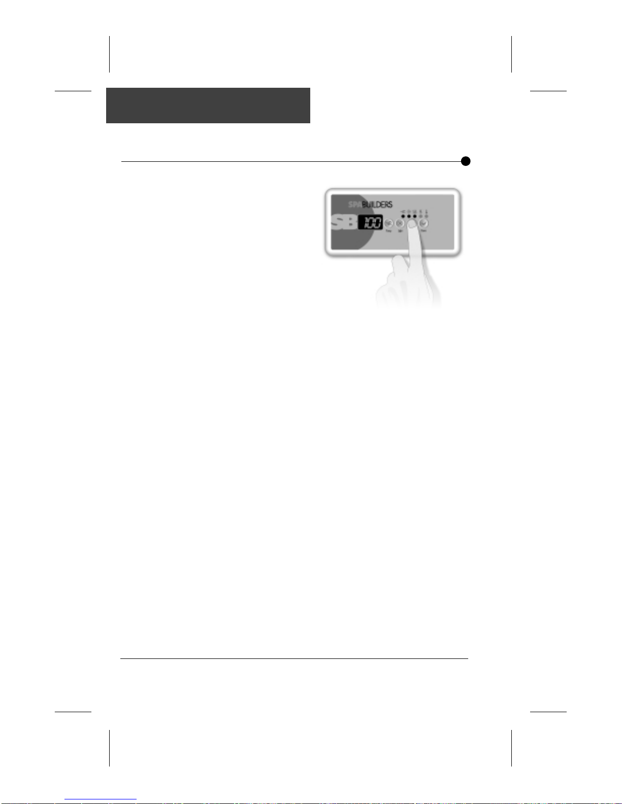
Instructions
Main Spa Side Control • Single Pump System
Up & Down Arrows
Automatic Water
Heater Start
Up & Down arrow keys are
used to set water temperature.
Keeping pressure on the
keys will increase (or
decrease) the current
temperature setting.
The new and desired
temperature setting will
remain for 5 seconds on
the LED display as a
confirmation of its new value.
The Set Point light indicator (K-18) or triangular icon (K-19) tells the
user that the temperature shown is the desired and not the actual
temperature of the water.The temperature can be adjusted in 1
degree increments from 59 to 104°F (15 to 40°C.).
When the water temperature is 1°F lower than the set point, the
heater will be turned on until the water temperature reaches the set
point plus 1°F. The "Heater" indicator lights up when the heater is on.
The "Heater" indicator will flash if there is a request for more heat
but the heater has not started yet.
Water Temperature
Display
The 3-digit LED display shows the water temperature reading.
The reading will be refreshed every second.
SC-CF-SBD Owner’s Manual34
Page 36
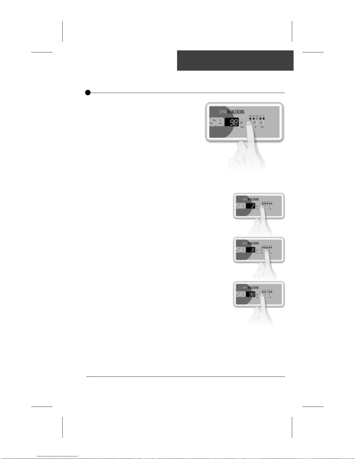
Instructions
Main Spa Side Control • Single Pump System
Filter Cycles
The system will automatically perform two filtering
cycles per day, 12 hours
apart. During a cycle, the
pump will start in high
speed for 1 minute then
will run in low speed for a
predetermined number of hours.
The ozonator is always on during a filter cycle.
To set the duration of the filtering cycle (the amount
of time the pump will be on), follow this procedure:
• Press Light key and hold for
5 seconds.
• The display will show a digit that
represents the duration of the
filter cycle in hours.
• Use Up & Down arrow keys
to change setting.
0 = no filtration
12 = continuous filtration
• When the desired setting is
displayed, press Light key
again. The filter cycle will start.
The "Filter" indicator lights up
when a filter cycle is on.
Note that after a power failure, the filter cycle duration will return to its default
value (6 hours, twice a day). In this case, the first filter cycle will start 12 hours
after power has been restored.
35SC-CF-SBD Owner’s Manual
Page 37
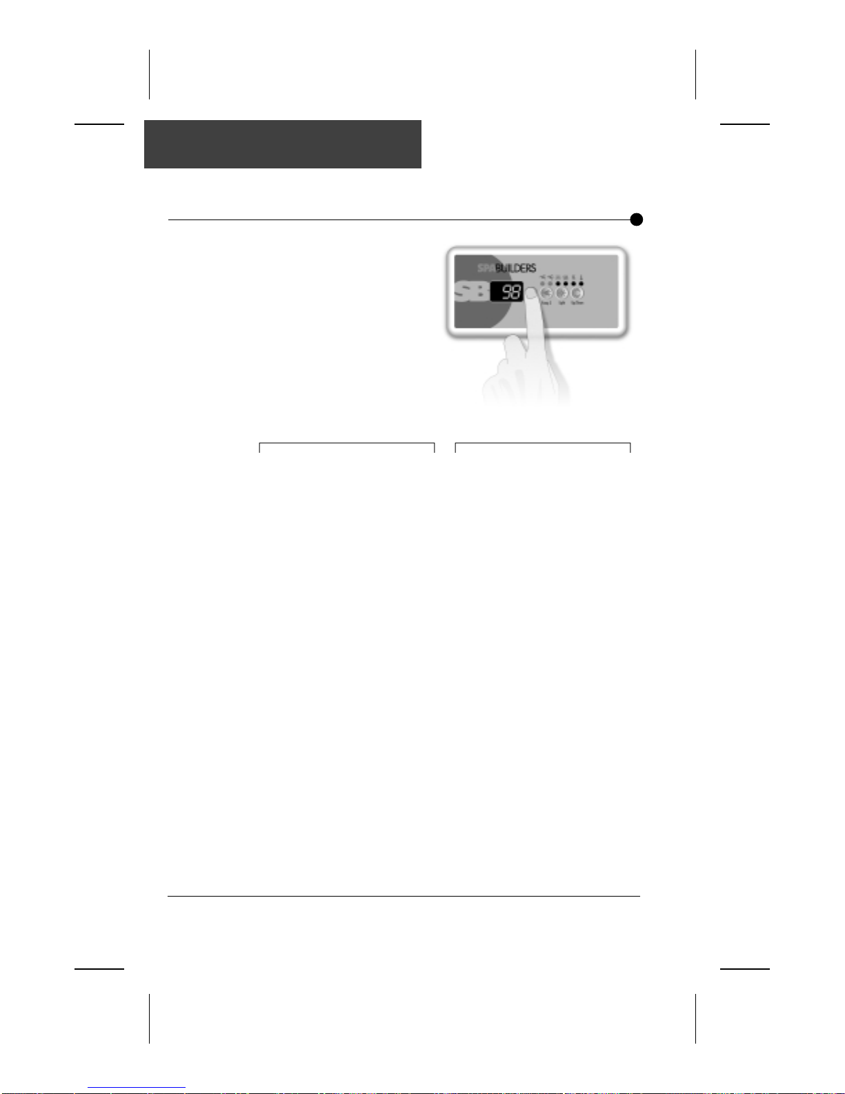
Instructions
Main Spa Side Control • Dual Pump System
Pump 1 & 2 Keys
Pump 1 key is used to turn
Pump 1 on or off and to
select speeds.
Pump 2 key is used to
either turn Pump 2 or
blower on and off.
Two-speed pump:
Pump 1 is a two-speed pump.
Pump 1 key is used to turn it on and
to select between off, low and high
speeds.
Press Pump 1 key to turn Pump 1
on. A second press will change
Pump 1 speed. A third press will
turn Pump 1 off.
1st press = low speed
2nd press = high speed
3rd press = off
A built-in timer will shut the pump
off 20 minutes after it has been
started unless the user does so
manually.
K-18: The "Pump 1" indicator
K-19: The "Pump 1" triangular
will appear on the function
panel when Pump 1 is
running.
icon will appear on the
display when Pump 1 is
running.
Pump 2 (or blower):Pump 1:
Single-speed pump (or blower):
Pump 2 (or blower) is a single-speed
pump (or a single-speed blower).
Pump 2 key is used to turn it on or
off.
Press Pump 2 key to turn Pump 2
(or blower) on. A second press will
turn Pump 2 (or blower) off.
A built-in timer will shut Pump 2
(or blower) off 20 minutes after it has
been started unless the user does so
manually.
K-18: The "Pump 2" indicator
will appear on the function
panel when Pump 2 or
blower is running.
K-19: The "Pump 2" triangular
icon will appear on the
display when Pump 2 or
blower is running.
SC-CF-SBD Owner’s Manual36
Page 38
Instructions
Main Spa Side Control • Dual Pump System
Light key
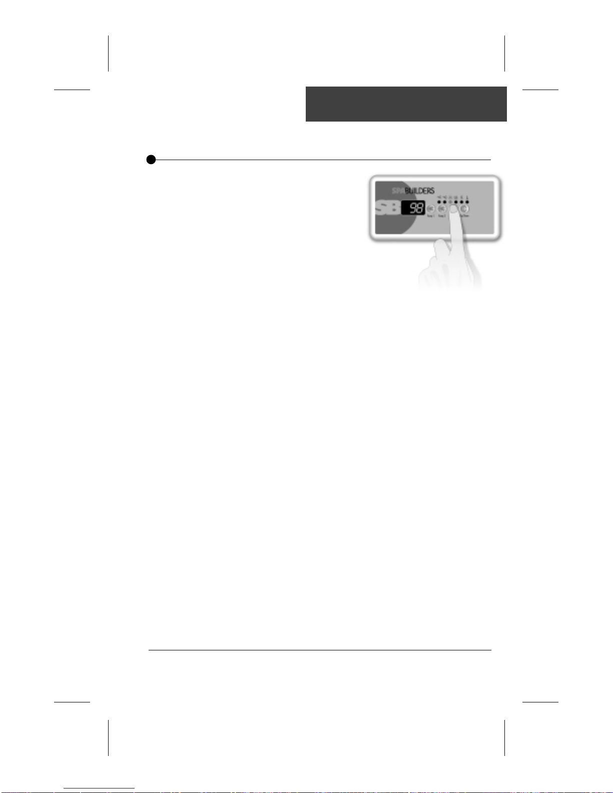
Light key is used to turn
light on or off.
The first press on Light key
will turn light on. A second
press will turn light off.
The light will automatically
shut itself off after 2 hours.
The "Light" indicator is displayed when light is on.
37SC-CF-SBD Owner’s Manual
Page 39
Instructions
Main Spa Side Control • Dual Pump System
Up & Down Arrows
Water Heater
Automatic Start
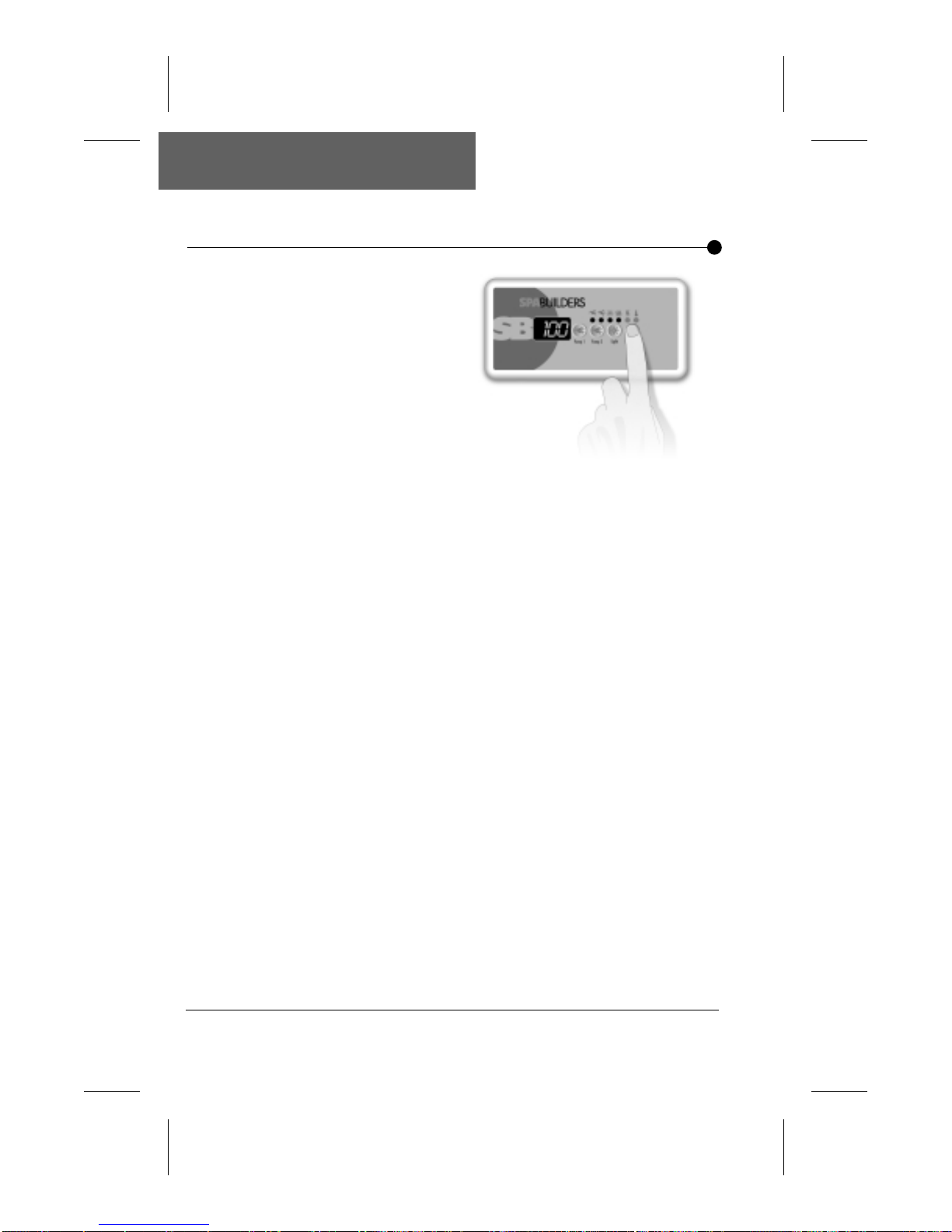
Up/Down arrow key is used
to set water temperature.
A first press on the key will
display the set point value.
Keeping pressure on the
key will increase the
desired temperature value.
To decrease the value of
the desired water
temperature, press again on Up/Down arrow key and hold
until the desired value is reached. The new and desired
temperature setting will remain for 5 seconds on the LED
display as a confirmation of its new value.
The Set Point light indicator (K-18) or triangular icon (K-19)
tells the user that the temperature shown is the desired and
not the actual temperature of the water. The temperature can
be adjusted in 1 degree increments from 59 to 104°F (15 to
40°C.).
When the water temperature is 1°F lower than the set point,
the heater will be turned on until the water temperature
reaches the set point plus 1°F. The "Heater" indicator (K-18)
or triangular icon (K-19) will appear when the heater is on.
Water Temperature
Display
The "Heater" indicator or icon will flash if there is a request for
more heat but the heater has not started yet.
The 3-digit LED display shows the water temperature reading.
The reading will be refreshed every second.
SC-CF-SBD Owner’s Manual38
Page 40
Instructions
Main Spa Side Control • Dual Pump System
Filter Cycles
The system will automatically perform two filtering
cycles per day, 12 hours
apart. During a cycle, Pump
2 (or blower) will run for
one minute at the beginning
of the cycle. Then Pump 1
will start in high speed for 1
minute and will run in low speed for a
predetermined number of hours.
The ozonator is always on during a filter cycle.
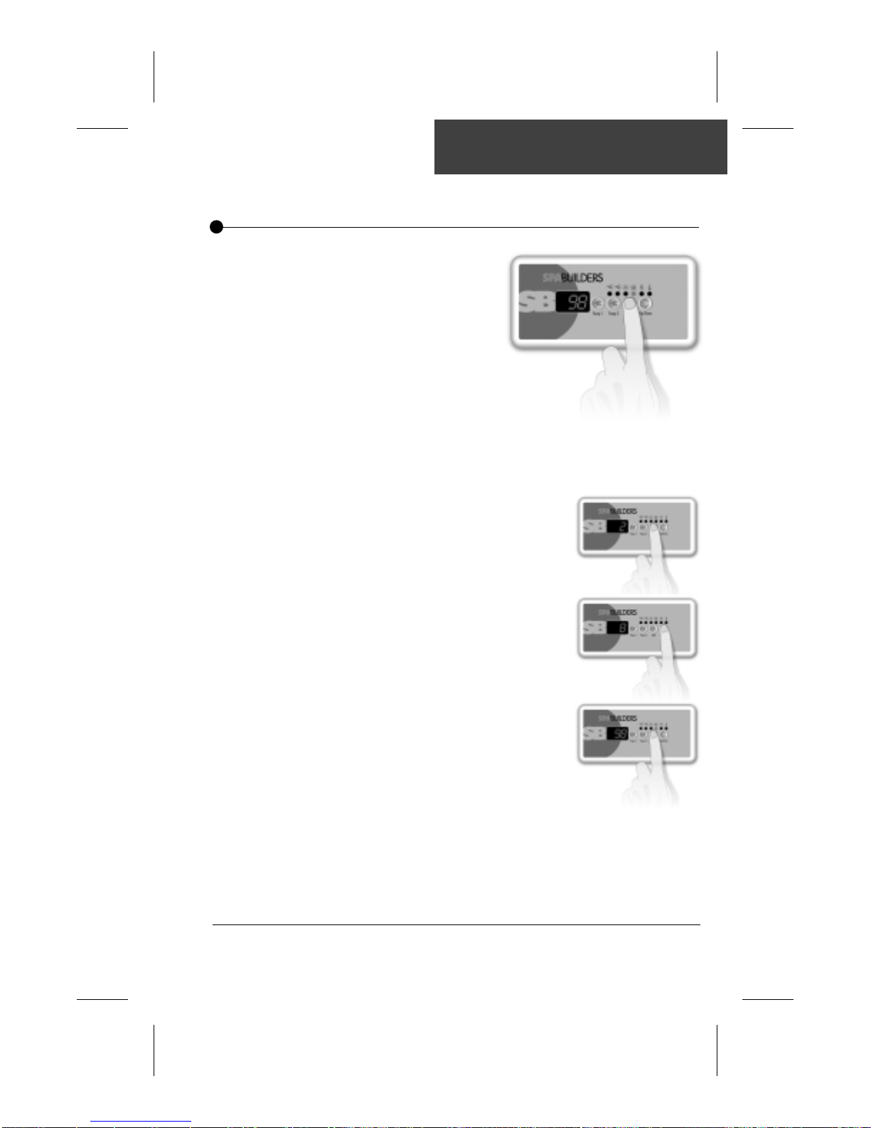
To set the duration of the filtering cycle (the amount of time
pump 1 will be on), follow this procedure:
•Press and hold Light key for 5
seconds.
•The display will show a digit that
represents the duration of the
filter cycle in hours.
•Use Up/Down arrow key to
change setting.
0 = no filtration
12 = continuous filtration
•When the desired setting is
displayed, press Light key
again. The filter cycle will start.
The "Filter" indicator lights up
when a filter cycle is on.
Note that after a power failure, the filter cycle duration will return to its
default value (6 hours, twice a day). In this case, the first filter cycle will
start 12 hours after power has been restored.
39SC-CF-SBD Owner’s Manual
Page 41
Instructions
Main Spa Side Control
Alarms
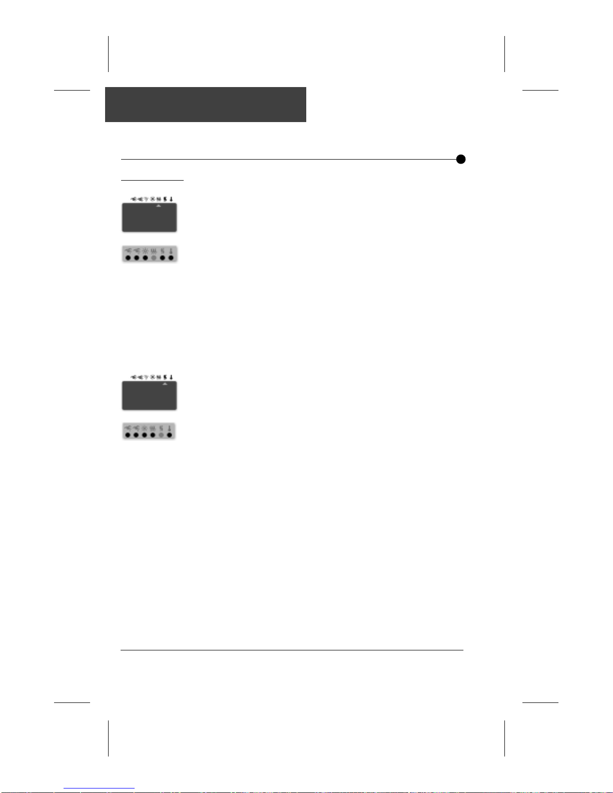
The pump occasionally starts by itself for 1 minute and "Filter"
indicator is flashing.
Not a bug but a feature! The Smart Winter Mode of your pack
protects your spa from the cold by turning pump on for 1 minute
several times a day to prevent water from freezing in the
plumbing.
These packs are equipped with a sensor that measures the
temperature of the air in the plumbing area of the spa. If the
system monitors air cold enough to freeze the water in the
pipes, it will automatically activate the Smart Winter Mode for a
period of 24 hours.
The "Heater" indicator is flashing when pump is on at high speed.
Not a bug but a feature! The system is turning the heater off
when pump is in high speed to limit the amount of electrical
current drawn.
SC-CF-SBD Owner’s Manual40
Page 42
Instructions
Error Conditions
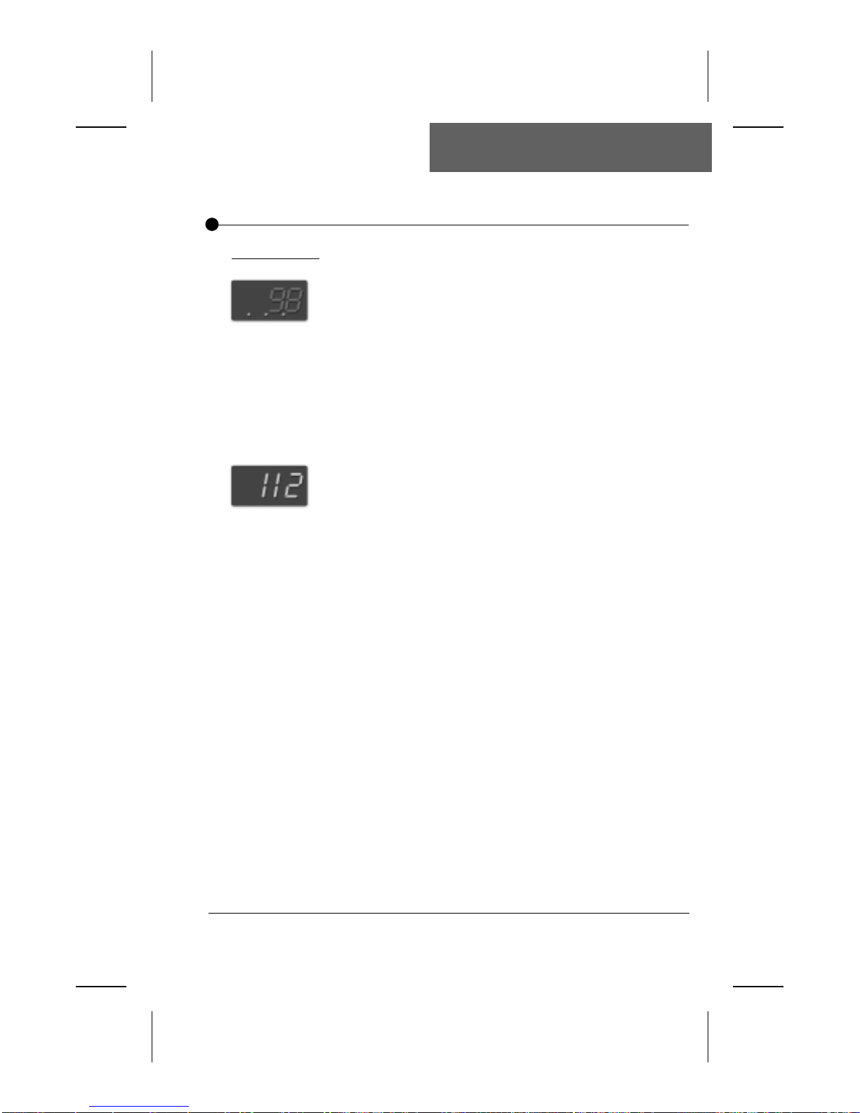
3 flashing dots appear on the display.
A problem has been detected. Do not enter the water! Check
and open water valves. Clean filter if necessary. Add water if
needed. Shut power off and power the spa up again to reset the
system.
Call your dealer or service supplier if problem persists.
The temperature flashes on the display.
Water temperature in the spa has reached 112˚F. Do not enter
the water! Allow water to cool down. The system will reset
automatically when water cools down to 109˚F.
Call your dealer or service supplier if problem persists.
The display is flashing.
A power failure has occurred. Press any key to stop the flashing
and reprogram your filter cycle.
41SC-CF-SBD Owner’s Manual
Page 43

Notes:
SC-CF-SBD Owner’s Manual42
Page 44
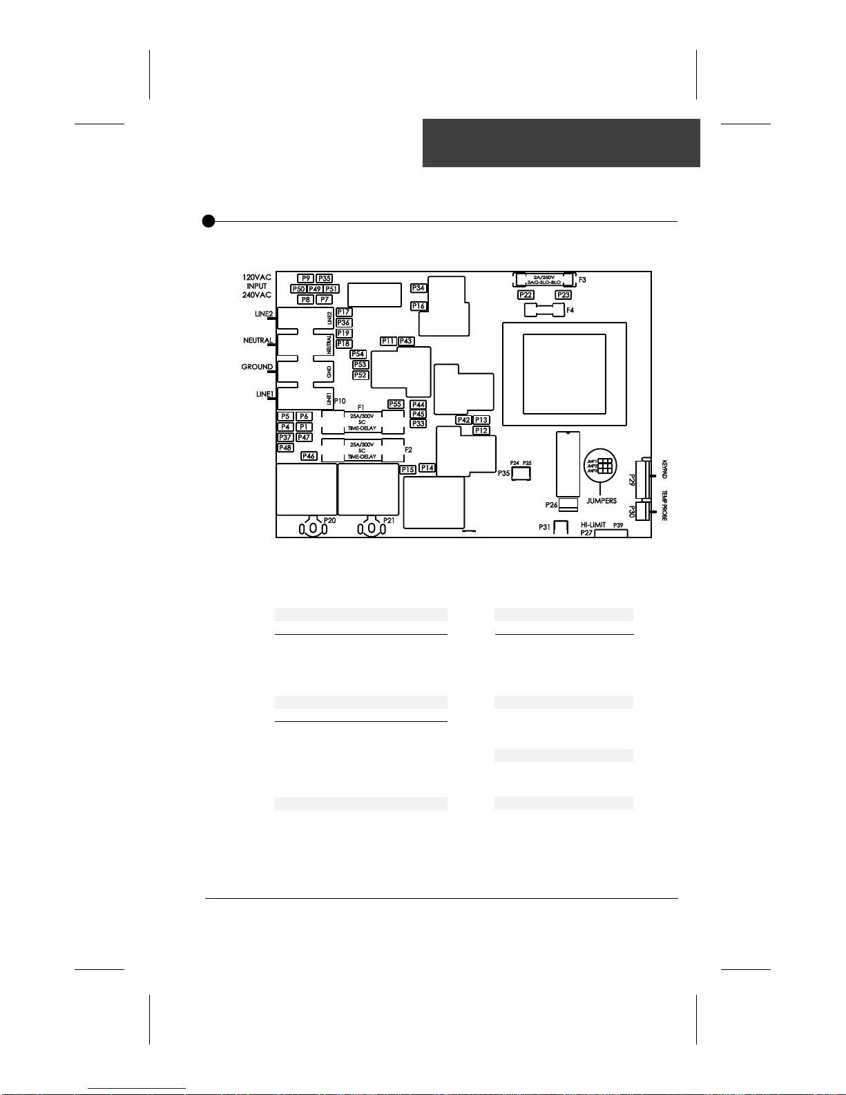
Wiring Diagram
Pump 1
Voltage 120v 240v
Green / Ground P4 P4
Black / Low Speed P14 P14
Red / High Speed P12 P12
White / Com P7 P18
Pump 2/Blower
Voltage 120v 240v
Green / Ground P6 P6
Black / Line P11 P11
Red / Line P43 P43
White / Com P9 P17
Jumper Settings
Refer to page 10
Ozonator
Voltage 120v
Green / Ground P5
Black / Line P16
Red / Line P16
White / Com P8
Light Connector
White / 0 VAC P23
Black / 12 VAC P22
Heater
Black 1 P20
Black 2 P21
Pressure Switch
Black P25
Black P24
43SC-CF-SBD Owner’s Manual
Page 45
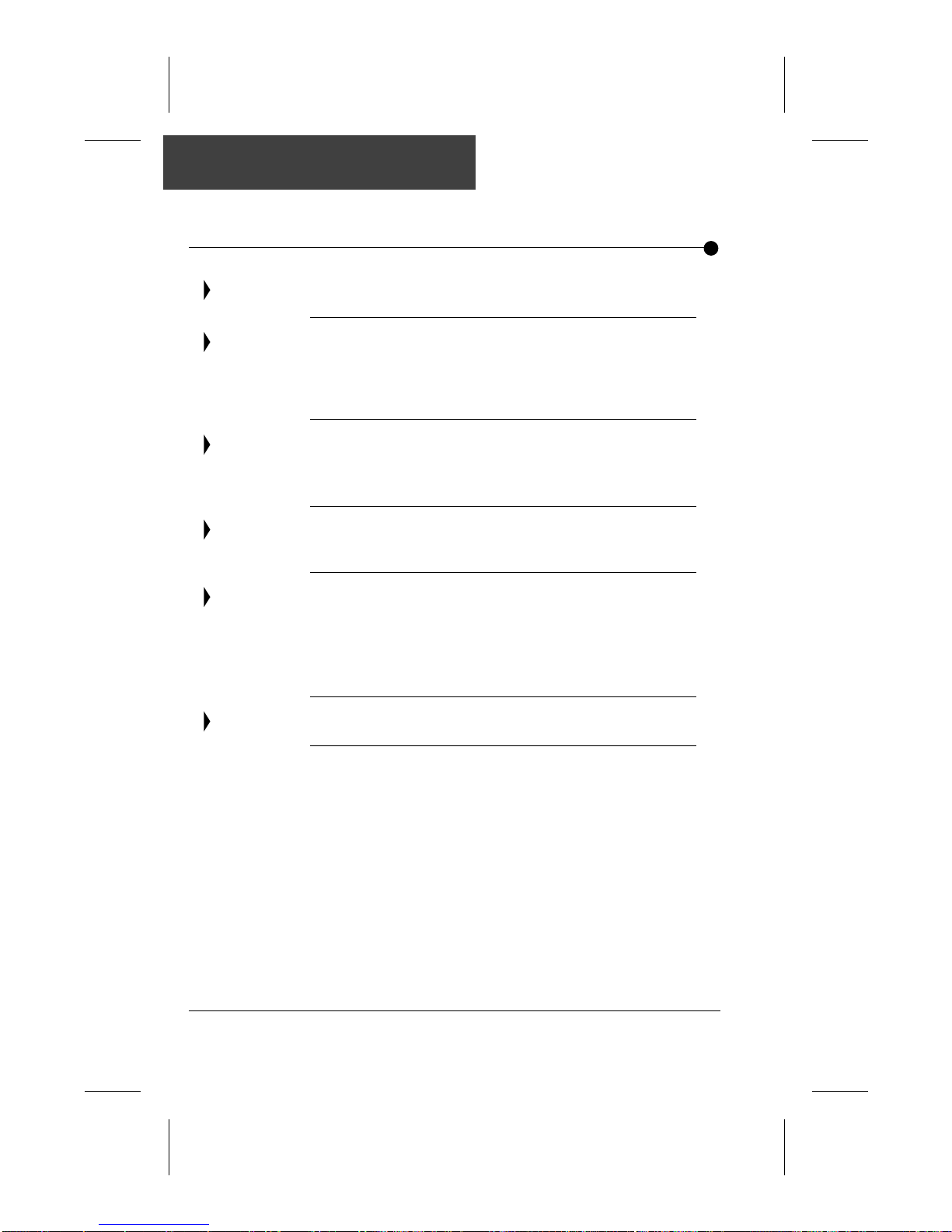
F actor y Default Settings
Filter Cycle
Jumpers
Outputs
Heaters
J&J
Set Point
- Filter cycle duration: 6hrs
- Jumper default settings: J1= HC
J2= Fº
J3= 2 Pump system
(or 1 Pump and 1 Blower)
- Pump 1: 120V output
- Pump 2: 120V output
- Ozonator: 120V output
- 240V= 4Kw Heater
- 120V= 1Kw Heater
- J&J color connector for pump 2,
1 speed connector installed
- Additional J&J color Blower connector plug
also supplied
- Water temperature at 95ºF
SC-CF-SBD Owner’s Manual44
Page 46
CLEARLY ADVANCED SPA SYSTEMS!
For more information about our spa packs
and all our other products and services,
visit our web site at
www.sbsg-equipment.com
™
E
G
C
K
H
O
T
'
I
S
W
E
D
X
E
C
P
L
P
U
I
S
U
I
V
Q
E
E
•
•
Smart
Winter
TM
Mode
9919-100375-B 3-85-7022-B
1.866.NEW.SBSG
(1.866.639.7274)
 Loading...