

Spa Builders SC-CF, SC-MP Service Manual
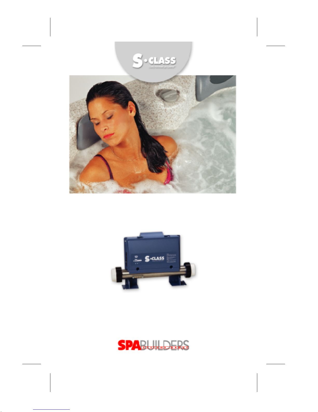
CLEARL Y ADVANCED SP A SYSTEMS!
SERVICE MANUAL
SC-CF & SC-MP SP A SYSTEMS TROUBLESHOOTING
VISUAL STEP- BY -STEP GUIDE & MORE!
™
TAKING OVER THE WA VES!

Topics covered in this manual are as follows:
Power & Ground Check
Electrical Wiring 6
GFCI 7
Programming
Jumper Positions 10
Error Conditions
3 Flashing Dots Appearing On Keypad Display 11
3 Flashing Dots & LED Displayed 15
Display Is Flashing 19
Wrong Temperature Appearing On Keypad Display 23
FLO 25
FLC 29
Prr 31
HL 33
Table of Contents
T roubleshooting
Nothing Seems to Work! 37
Spa Does Not Heat! 41
Pump 1 Does Not Work! 45
Pump 2 (or Blower) Does Not Work! 49
Light Does Not Work! 53
Ozonator Does Not Work! 55
Keys Do Not W ork! 57
How to ...
Replace The Spa P ack 59
Adjust The Pressure Switch 62
Miscellaneous
Wiring Diagrams 64
Professional Repair Kit Info 66

In an attempt to make this manual as useful as possible, it has been presented in two
formats. Problem-solving solutions are described with Troubleshooting Flow Charts
and also with Step-by-Step Procedures.
The two formats together should provide an overall complete explanation, with flow
charts providing an overview of specific problems, and step-by-step procedures giving
more detailed information.
Important Safety Information
WARNING: Risk of electrical shock! All procedures described in this service manual
must only be performed by qualified personnel, in accordance with the
standards applicable in the country of installation and, whenever
possible, with the equipment powered off. When connecting the
equipment, always refer to the wiring diagram affixed to the inside of
your spa pack’s power box cover! This diagram always prevails over
the wiring diagram at the end of this manual.
All information given subject to technical modifications without notice.
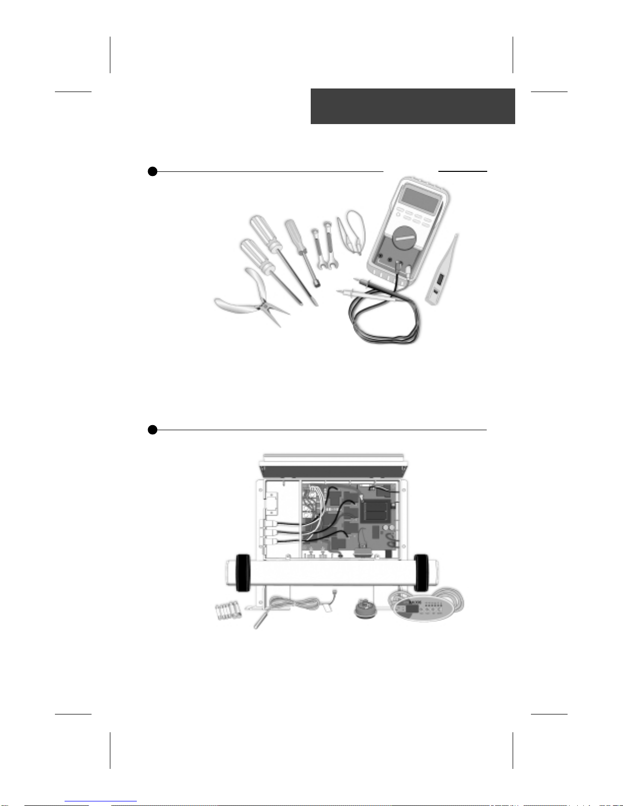
Tools, test equipment and components needed to carry
out SC-CF and SC-MP spa pack service calls.
Required tools:
Tools & Parts
Pliers
Phillips & flat screwdrivers
11/32
" nut driver
1/4
" open end wrench
Required pack parts:
Fuses
Pressure Switch
Regulation sensor
3/8
" open end wrench
Jumper cable
Multimeter
GFCI tester & digital thermometer
Top side control (keypad)
SC-CF / SC-MP complete pack
(optional)
Spa Builders Systems Group sells Professionnal Repair Kits that include everything needed for SC-CF and SC-MP spa pack
servicing. For more information, go to the last page of this manual.

4 SC-CF & SC-MP Service Manual
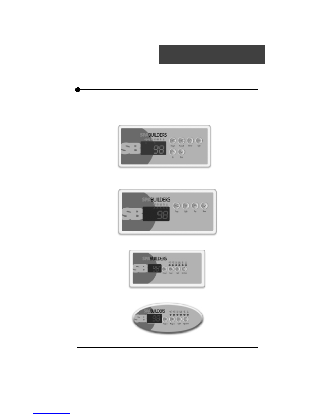
Keypads
SC-CF and SC-MP single- and dual-pump systems are available with
a selection of keypads.
All the procedures and instructions described in the next pages are applicable to
SC-CF and SC-MP systems equipped with one of the following keypads. Please
note that the K-9 model is used througout this manual to illustrate specific actions.
SC-MP (only)
1/4
K-35 Keypad (7" • 3
SC-CF
")
K-19 Keypad (7" • 3
K-18 Keypad (5" • 2
K-9 Keypad (2" • 4
1/4
")
1/2
")
1/2
")
5SC-CF & SC-MP Service Manual
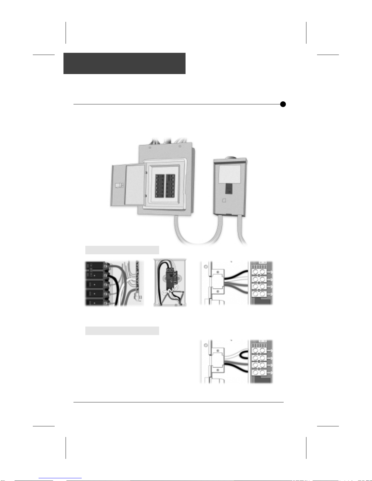
Electrical Wiring
Correct wiring of the electrical service box, GFCI box and pack terminal
bloc is essential.
1• Carry out a visual inspection to check for signs of miswiring.
Refer to supplied wiring diagrams.
Call an electrician if necessary .
For 240 VAC systems:
L2
N
G
L1
Electrical Box GFCI Pack Terminal Block
For 120 VAC systems:
L2
N
G
L1
Pack Terminal Block
6 SC-CF & SC-MP Service Manual
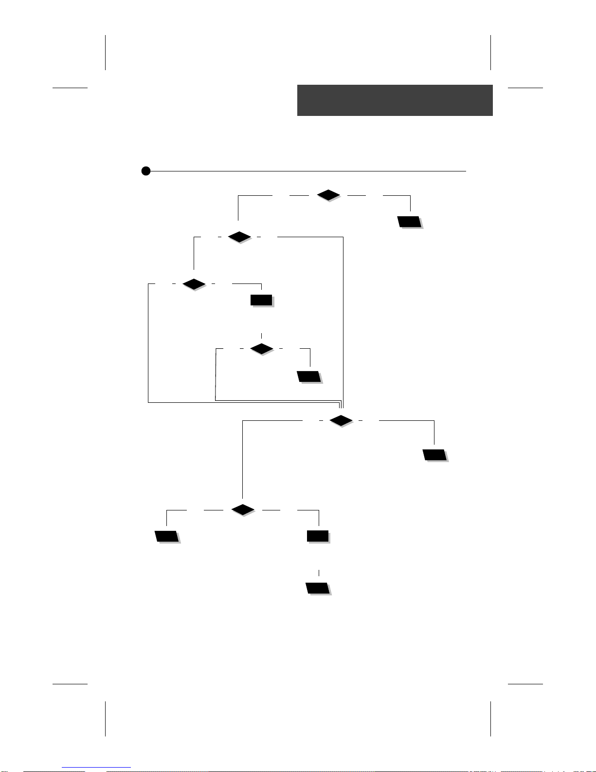
GFCI Flow Chart
If GFCI trips, follow this Troubleshooting Flow Chart to identify
the problem:
yes no
Is GFCI
properly connected?
yes no
Wiring Diagram
and reconnect it.
a 120 VAC system?
yes no
Is Jumper #1
in LC position?
(see page 10)
Is Spa Pack
Change
Jumper #1 position.
yes no
Is GFCI
still tripping?
Verify
There is
a problem
with the
cable.
Call an
electrician!
yes no
If GFCI is
still tripping,
disconnect
incoming
power line.
Is GFCI
still tripping?
yes no
Unplug everything
including the two blades
of the heater & light cord.
Is GFCI
still tripping?
Replace
GFCI.
Replace Spa Pack
if GFCI is still tripping.
Reconnect
one component
at a time until
GFCI starts tripping.
Replace defective
component.
7SC-CF & SC-MP Service Manual
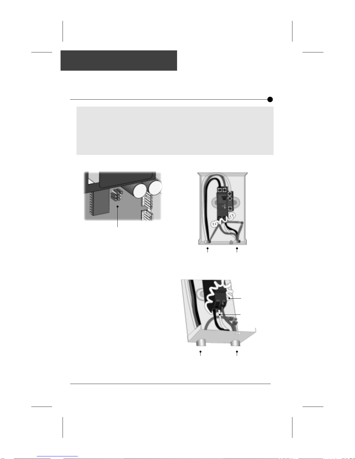
GFCI Trips!
If all connections are made, but nothing seems to be working, you
probably have a power supply problem. Carry out the following tests
to identify and correct the problem:
Note that for new installations, GFCI trippings due to miswiring are common. If
breaker is wired properly , GFCI trippings may occur when total amount of current
drawn by spa exceeds breaker rating.
A current leak to ground will also cause GFCI to trip. If any of the components is faulty
and a leak of more than 5mA occurs, GFCI will trip to prevent electrocution.
There are different GFCI models on the market. Note that illustrations are generic only .
For 120 VAC systems: For 240 VAC systems:
Jumper location
1• Verify if Jumper #1 is set in
the LC position. If it is not,
set Jumper #1 in the LC
position.
Refer to page 10 for more
information on jumpers.
From electrical box To spa
1• Verify if GFCI is properly
connected.
Important
connections:
Neutral of GFCI
must be connected
to neutral bus.
Neutral from spa
must be connected
to breaker .
From electrical box To spa
2• If it is not, verify GFCI wiring
diagram and reconnect it.
8 SC-CF & SC-MP Service Manual
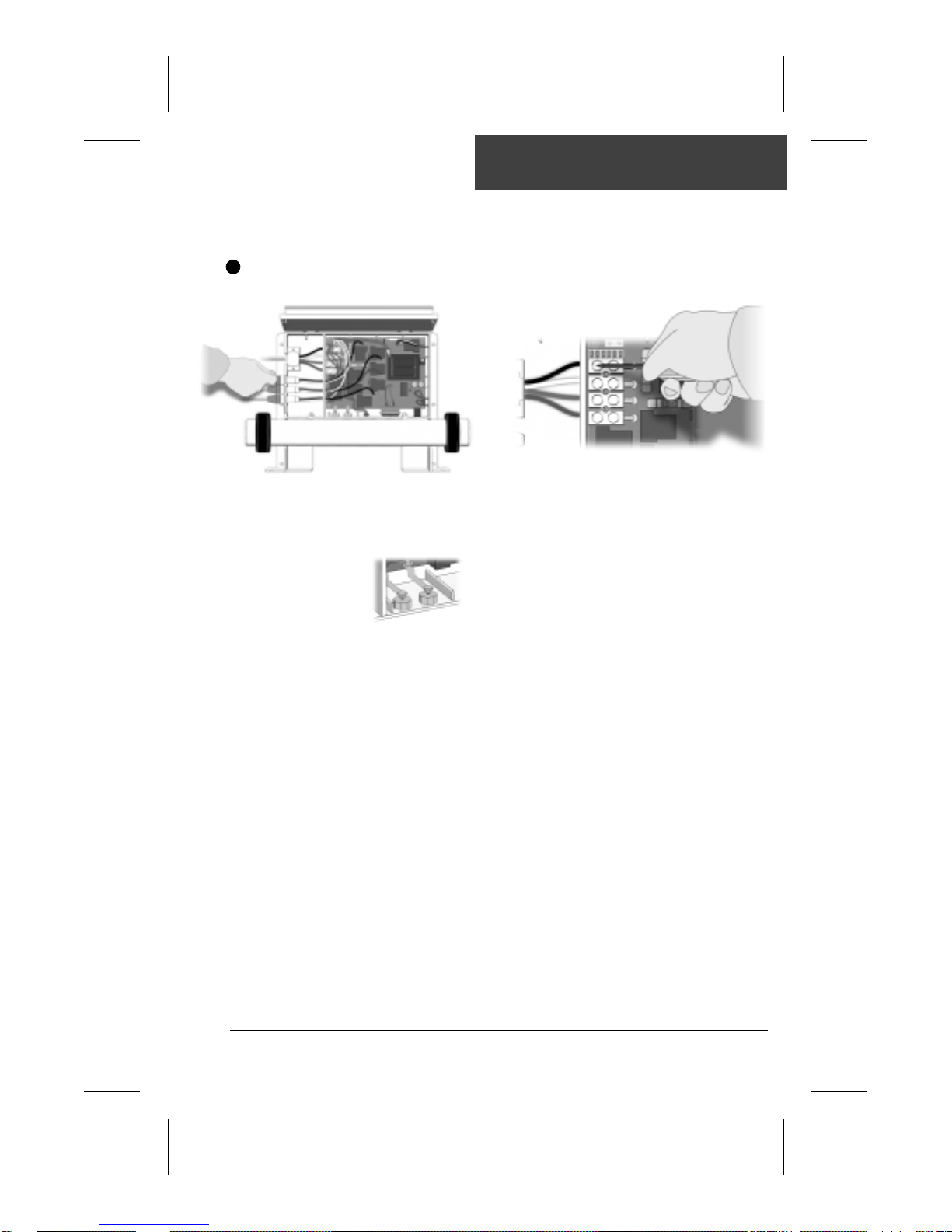
If GFCI continues to trip carry out the following tests to correct
the problem:
GFCI Trips!
1• If GFCI is properly connected, but
still tripping, (or Jumper #1 is set in
LC mode for 120 VA C systems),
unplug all outputs
including the
two blades of
the heater
and light cord.
2• If GFCI still trips, replace Spa Pack.
If it stops tripping, reconnect one
component at a time until GFCI
starts tripping. Replace defective
component.
3• If problem is not solved yet,
disconnect incoming power
lines.
If GFCI still trips, there must be
a cable problem.
Call an electrician!
4• If GFCI stops tripping, replace
GFCI.
5• If GFCI trips again, replace
Spa Pack.
9SC-CF & SC-MP Service Manual
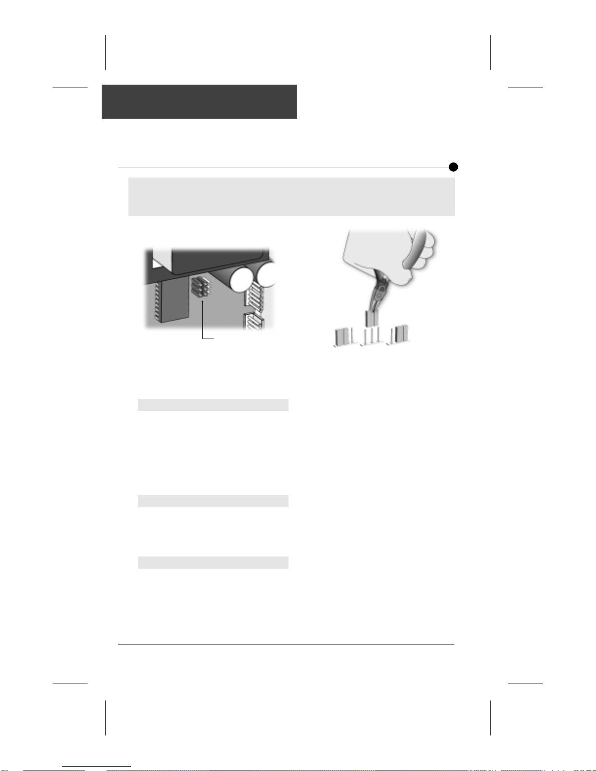
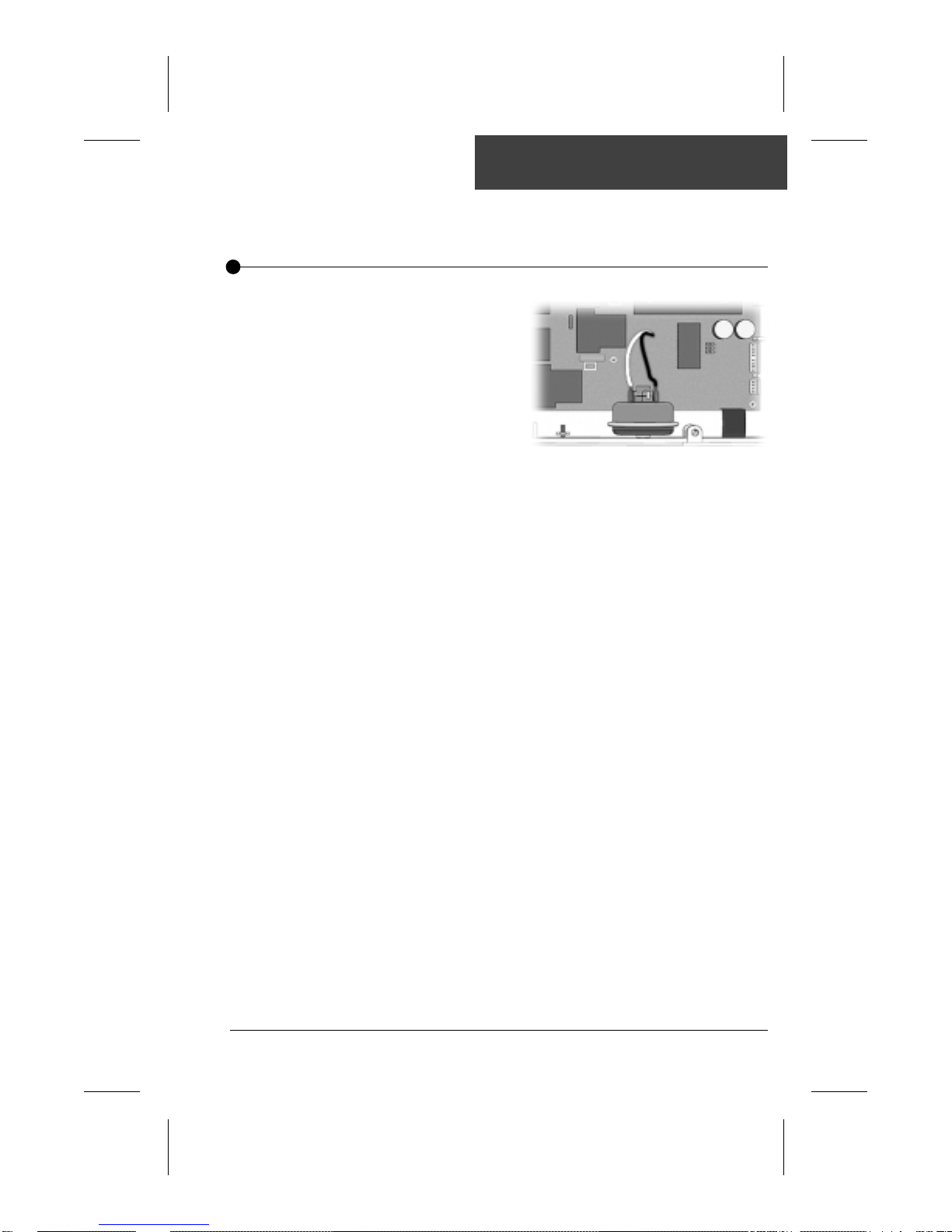
Jumper Positions
Certain parameters can be modified by changing the position of jumpers
on the board.
To access jumpers, first remove SC-CF or SC-MP power box cover.
In some cases, jumper functions may differ from the following. Please check wiring
diagram on power pack box cover to verify specific functions for your pack.
Jumpers
Position 2Position 1
1• Jumpers are located in the lower
right section of the board.
Jumper 1: Current Limiting Option
Jumper 1 is used to limit amount of current drawn when the 2 pumps are on.
Position 1 (HC): System turns heater off when the two pumps are on
Position 2 (LC)*: System turns heater on when one pump is on at high
*Mandatory for 120 VAC systems
Jumper 2: Temperature Unit
Jumper 2 is used to select the temperature unit.
Position 1: Temperature will be displayed in Fahrenheit degrees.
Position 2: Temperature will be displayed in Celsius degrees.
Jumper 3: Pumps
Position 1: Single-pump.
Position 2: Dual-pump (or blower).
at high speed.
speed. The "Heater" icon flashes on display indicating
that more heat is requested, but heater is not allowed
to start.
2• To change a setting, simply pull cover
off and replace in desired position.
10 SC-CF & SC-MP Service Manual
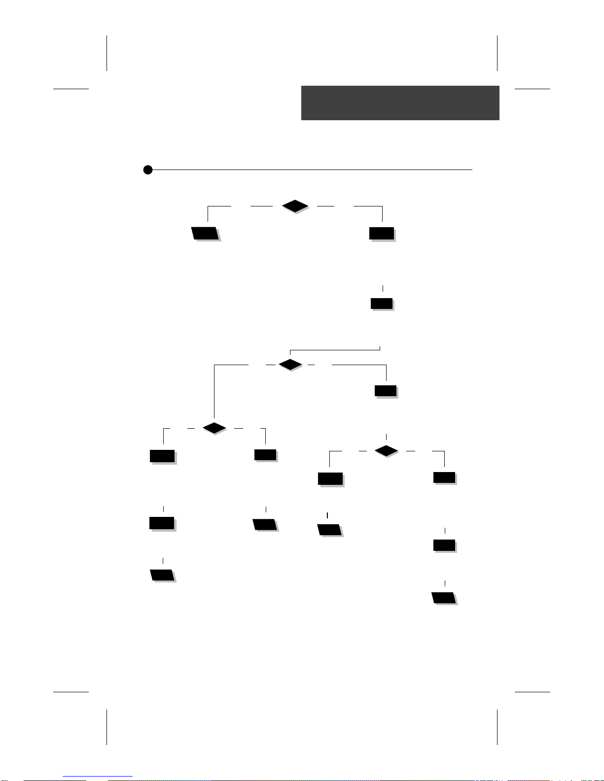
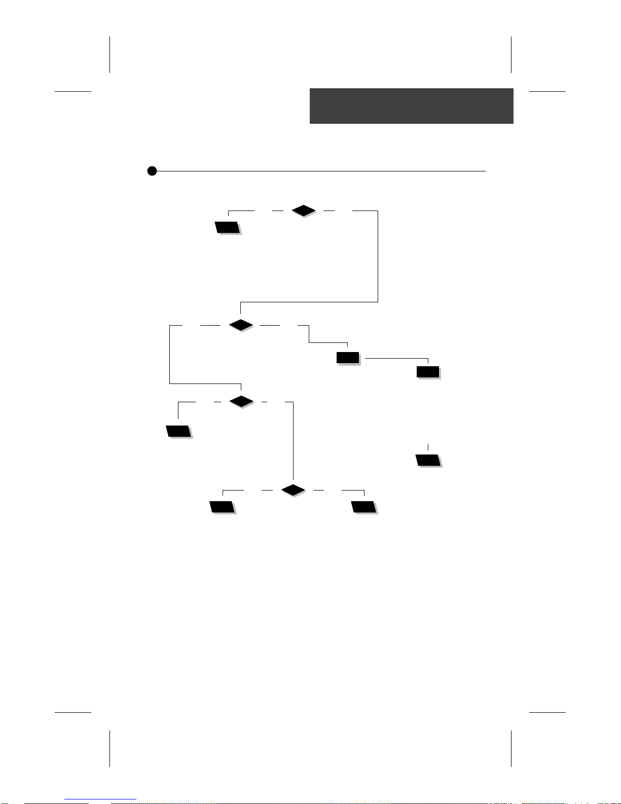
Flashing Dots Flow Chart
If 3 flashing dots appear on keypad display, follow T roubleshooting Flow
Chart below to identify the problem:
3 flashing dots appear on the display!
yes no
Remove pack cover.
Follow
Is board LED on?
flashing dots
& LED flow chart.
yes no
Do you have
continuity on your
voltmeter for
pressure switch?
yes no
Make sure jumper is
set properly for
circulation pump and
reset breaker.
Start Pump 1 (or
circulation pump if installed
by increasing set point).
Short pressure
switch terminals
with a jumper cable.
Verify
pressure
switch
connection.
Replace pressure
switch cable.
If problem persists,
replace Spa Pack.
Disconnect
pressure switch
for 5 seconds
and reconnect it.
Are dots still
flashing on
keypad display?
Try
to adjust
pressure
switch.
Replace
pressure
switch
if problem
persists.
yes no
Replace pressure
switch cable.
If problem persists,
replace Spa Pack.
Are dots still
flashing on
keypad display?
Remove anything
obstructing filter canister
or piping. Clear any air
locks. Verify water valves.
Try to adjust
pressure switch.
Replace pressure
switch if problem
persists.
11SC-CF & SC-MP Service Manual

Flashing Dots Displayed
Three flashing dots error condition indicates a pressure switch problem.
There must be enough water in the spa for normal operations. System may detect error
condition if spa filter is dirty or if something restricts flow of water in piping.
The heater will automatically shut down when error condition occurs.
Power may remain On when the following steps are carried out.
1• Verify if Pump 1 (or circulation
pump if installed) is working. If
pump is not working right, refer
to pump section of this manual.
2• Make sure jumper is set pro-
perly for circulation pump.
3• If Pump 1 is working properly,
turn it on by pressing Pump 1
key (or start circulation pump
by increasing the set point) and
test continuity on pressure switch.
4• If you detect continuity, go to
step #10.
5• If you do not detect continuity,
verify if pressure switch cable is
properly connected to pressure
switch and board.
12 SC-CF & SC-MP Service Manual
6• Ensure adequate water flow in the
heater and short two pressure switch
terminals with jumper cable.
7• If the three dots disappear, first
make sure there is no blockage of
water or air lock and check water
valve.
If the installation is older than 2 years,
replace the pressure switch and recalibrate it.
If installation is recent, try readjusting the pressure switch. If this is not
possible, replace switch.
(Refer to "How to Adjust the
Pressure Switch" section of this
manual.)
Flashing Dots Displayed
8• If the three dots still appear, the
problem may be either with switch
cable or board.
Remove plastic cover and replace
cable.
9• Replace Spa P ack if error condition
still persists.
(Refer to "How to Replace the Spa
Pack" section of this manual.)
13SC-CF & SC-MP Service Manual

Flashing Dots Displayed
Power may remain On while the following steps are carried out.
10• If you have continuity on pressure
switch, follow these steps:
Disconnect pressure switch cable
for 5 seconds and reconnect it.
If error condition disappears, ad-
just pressure switch, if it is a new
installation (less than two years) or
replace it.
(Refer to "How to Adjust the
Pressure Switch" section of this
manual.)
11• If error condition persists, remove
plastic cover and replace pressure
switch cable.
12• Replace Spa Pack if error condition
still persists. (Refer to "How to Re place the Spa Pack" section of this
manual.)
14 SC-CF & SC-MP Service Manual
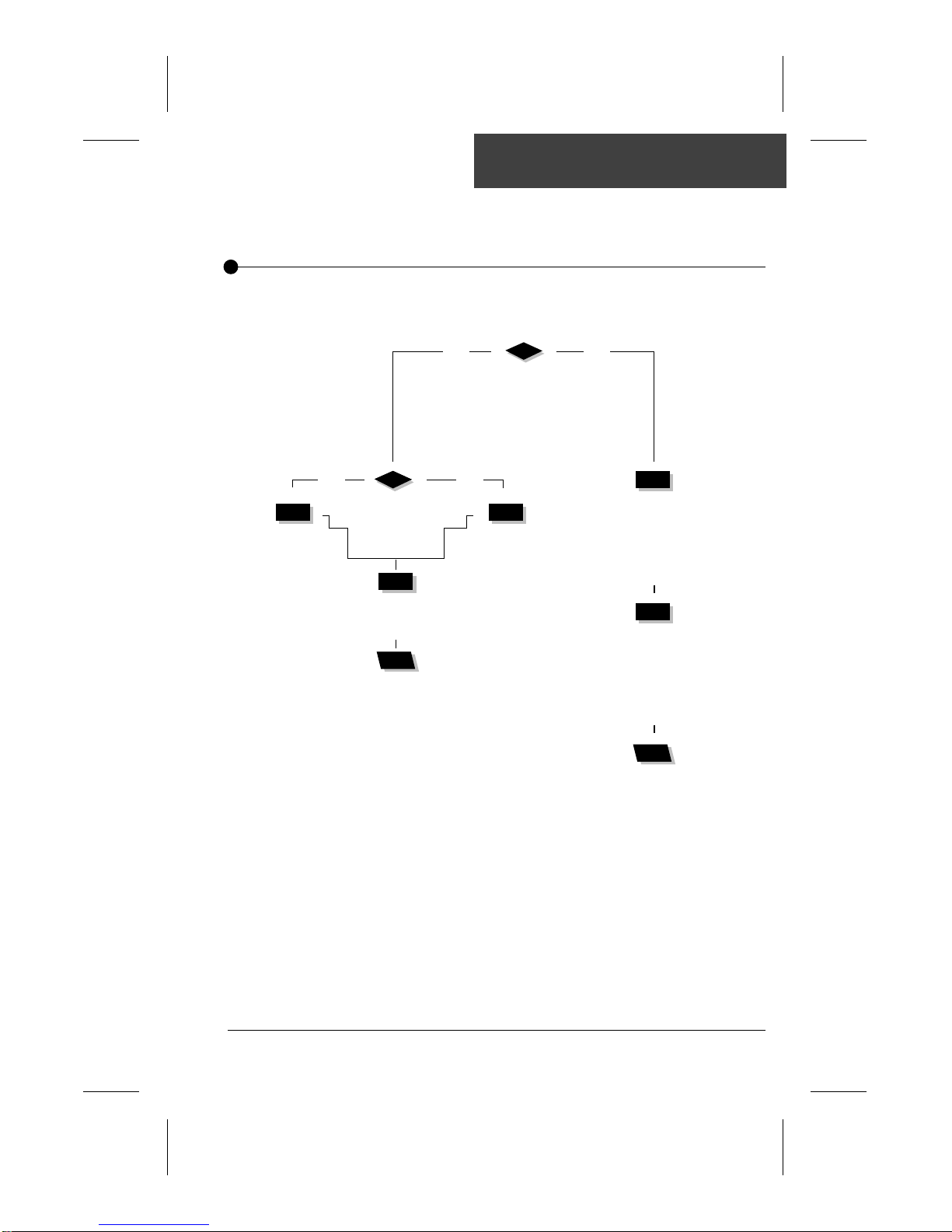
Flashing dots and LED Flow Chart
If error condition occurs (potential Hi-Limit sensor or temperature probe
problem), follow Troubleshooting Flow Chart below to identify the problem:
Turn breaker off then on again to reset the system.
If Hi-Limit condition no longer persists,
check for blockage of water in the piping.
yes no
Take water temperature
with a digital thermometer.
Are you getting correct
water temp. reading on the display?
yes no
Verify if anything
is obstructing water
flow (closed traps or
dirty filters).
When error
condition occurs,
does heater
barrel feel hot?
If error condition
persists, replace probe
and reset breaker.
If error condition still
persists, replace Spa Pack.
Is HL probe
properly connected?
Clean pins, reconnect
it, and reset
the breaker.
Verify if
temperature probe
is touching water
or if cold air from
back can affect
reading.
Verify if
temperature probe
is properly connected.
If so, replace probe
and reset breaker.
Replace Spa Pack
if error condition
still persists.
15SC-CF & SC-MP Service Manual
Flashing Dots & LED Displayed
The three flashing dots and LED error condition is related to the Hi-Limit sensor
or temperature probe.
Turn breaker off then on again to reset the system.
If 3 flashing dots and LED disappear, wait until they are displayed again on keypad.
Power may remain On.
1• Take water temperature with a
digital thermometer.
2• If keypad display shows correct
temperature:
a- Check if heater barrel feels hot.
If it's hot, verify if anything is
obstructing the flow of water
(closed valves or dirty filter).
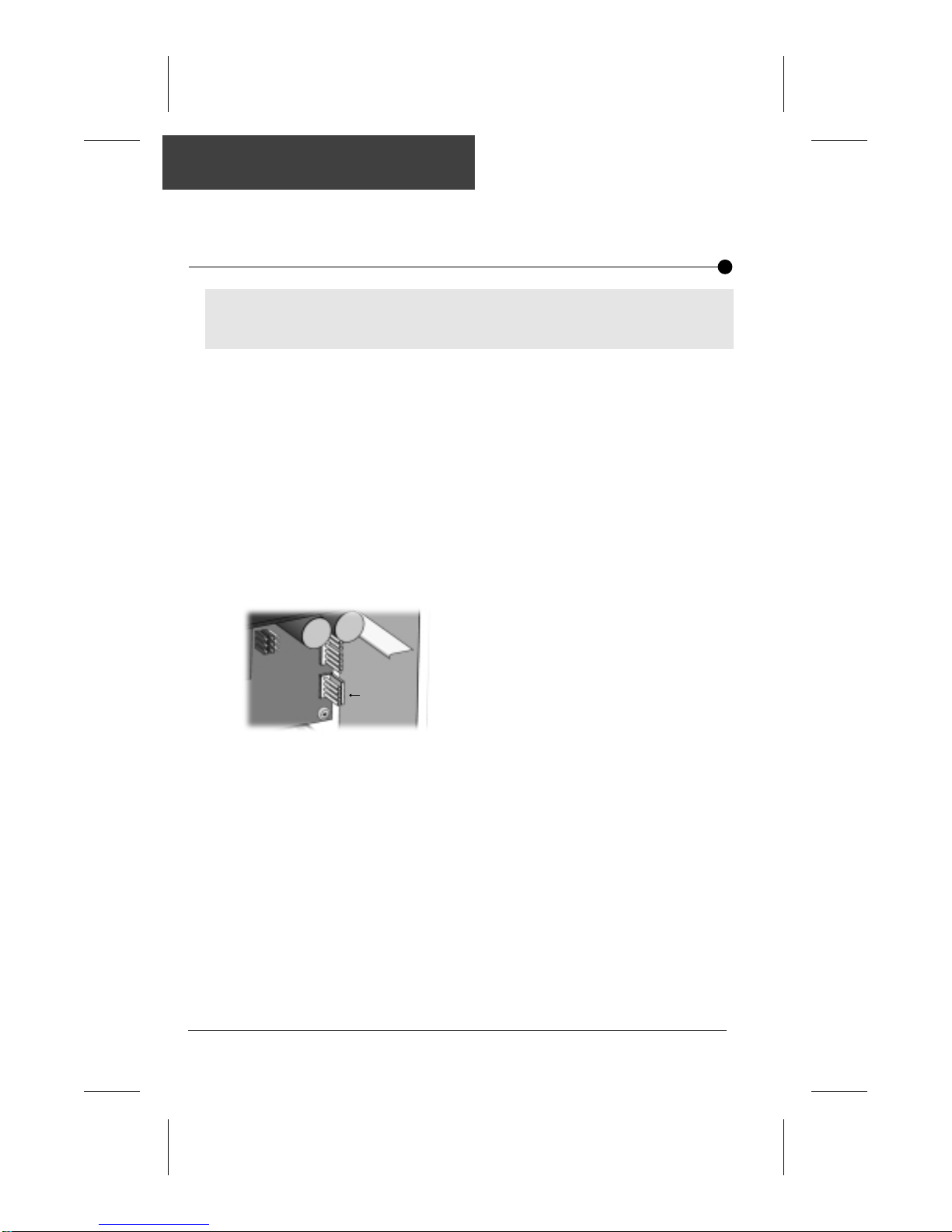
b- If it's not, verify if hi-limit probe
is properly connected.
Probe
connector
pins
Try to clean probe connector
pins. Even a small coating of film
can cause a bad connection.
Reconnect probe and reset
breaker.
c- If error condition persists, re-
place probe and reset breaker.
d- If problem is not corrected, re-
place Spa Pack. (R efer to "How
to Replace Spa P ack" section of
this manual.)
3• Proceed to following page if
keypad display shows incorrect
temperature.
16 SC-CF & SC-MP Service Manual

Flashing Dots & LED Displayed
If keypad display isn't showing correct temperature, carry out the
following tests:
1• Verify if temperature probe is
in contact with water and if
cold air from the back could
be affecting readings.
Use foam to isolate probe from
cold air if that is the problem.
2• Make sure temperature probe
is properly connected.
If it is, replace probe and reset
breaker.
3• Replace Spa P ack if error con-
dition still persists. (Refer to
"How to Replace Spa P ack"
section of this manual.)
17SC-CF & SC-MP Service Manual

18 SC-CF & SC-MP Service Manual
Display Flashing Flow Chart
On certain packs, if system detects temperature at 112°F or higher,
the display will start flashing. Follow Troubleshooting Flow Chart below
to identify the problem:
yes no
Press
any key .
A power failure
has occurred.
System
works fine.
yes no
Are you getting correct
water temp. reading on the display?
yes no
Is weather
very hot?
Remove
spa cover
(even during
the night).
Start
blower, if
spa is
equipped
with one.
Wait until
spa cools
down (add
cold water
if needed).
Replace
Spa Pack.
yes no
Has display
stopped flashing?
Lower set point
below actual
temperature of
water.
"Heater" indicator
on keypad display
should disappear.
Do you get a
240 VAC reading
between
two heater wires
on the board?
Verify if
temperature probe
is touching water
or if cold air from
back can affect
reading.
Pump is
overheating
water during
filter cycle.
Lower
filter cycle
duration.
Verify if
temperature probe
is properly connected.
If so, replace probe
and reset breaker.
Replace
Spa Pack
if problem
still persists.
19SC-CF & SC-MP Service Manual
Display Is Flashing
If digital thermometer water temperature reading is 112°F or higher and
keypad display indicates correct temperature, carry out the following
tests:
If display stops flashing after pressing a key, this means that a power failure has occurred.
System works fine.
If weather is very hot:
1• Remove spa cover (even during
the night). Start blower if spa is
equipped with one. Wait until
spa cools down (add cold water
if necessary).
If hot weather is not a factor:
2• Lower Set P oint below current
water temperature.
The "Heater" indicator should
disappear from keypad display.
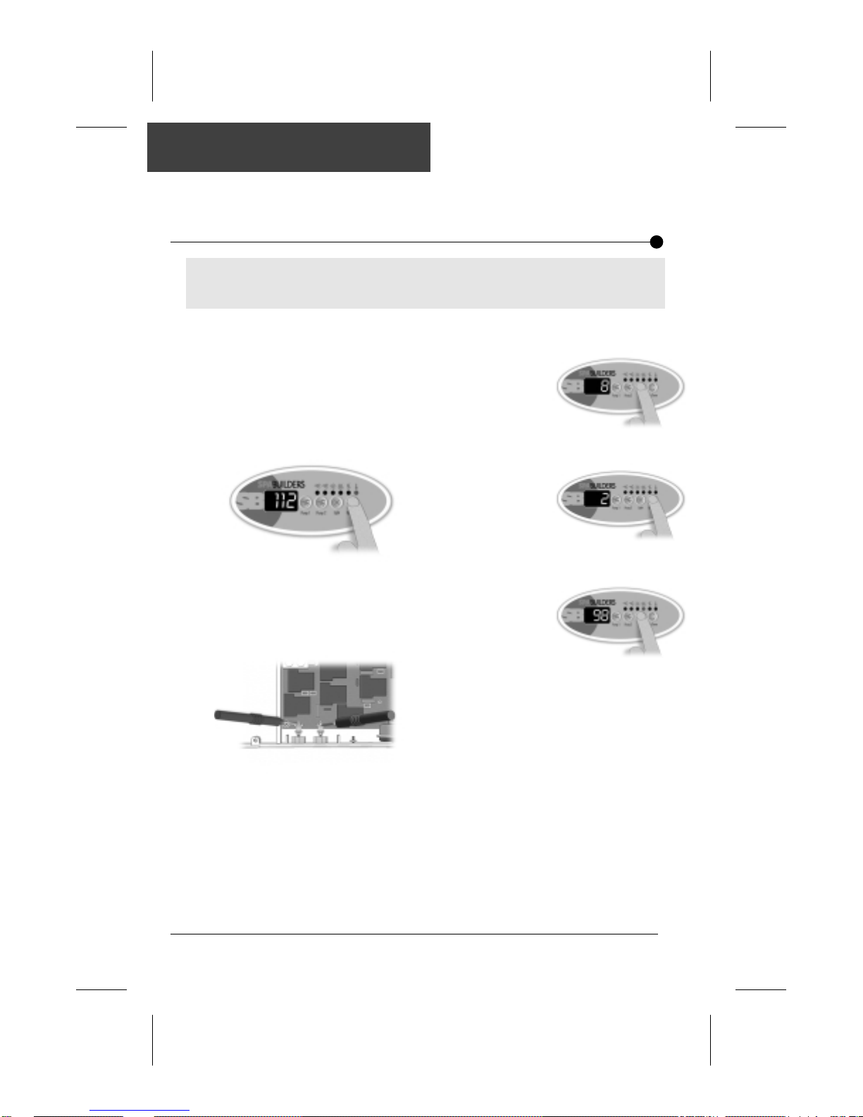
T o shorten filter cycle duration:
5• Press and hold
Light key for
5 seconds.
Display will
show a value
that represents the filter
cycle duration in hours.
Use Down
arrow key
to lower
the number
of hours.
0 = no filtration
12 = continuous filtration
When the
desired setting
is displayed,
press Light key
again. The filter
cycle will start
immediately.
6• If you do read 240 VAC,
replace Spa Pack.
3• Remove plastic cover. With a volt-
meter, read voltage between the
two heater wires on the board.
4• If you do not read 240 VAC, pump
may be overheating water during
filter cycle.
Shorten filter cycle duration.
20 SC-CF & SC-MP Service Manual
 Loading...