

Page 1

SILENT-100
Instrucciones de montaje
Instruction leaflet
Notice de montage
Montageanweisungen
Montage-en gebruiksaanwijzing
Instrucções para a montagem
Istruzioni per l'installazione
Användar instruktion
Brugervejledning
Instrukcja obslugi
Návod
Käyttöohjeet
Инструкции по сборке
Page 2
1
4
2
3
Fig.1
Page 3
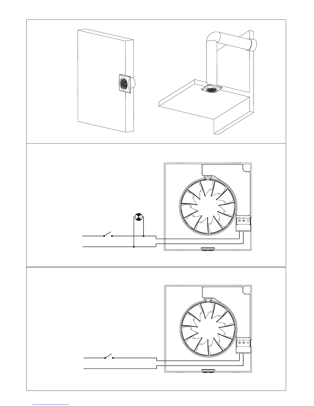
Fig.2
Fig.3
L
L
NNLs
L
Fig.4
L
NNLs
Page 4
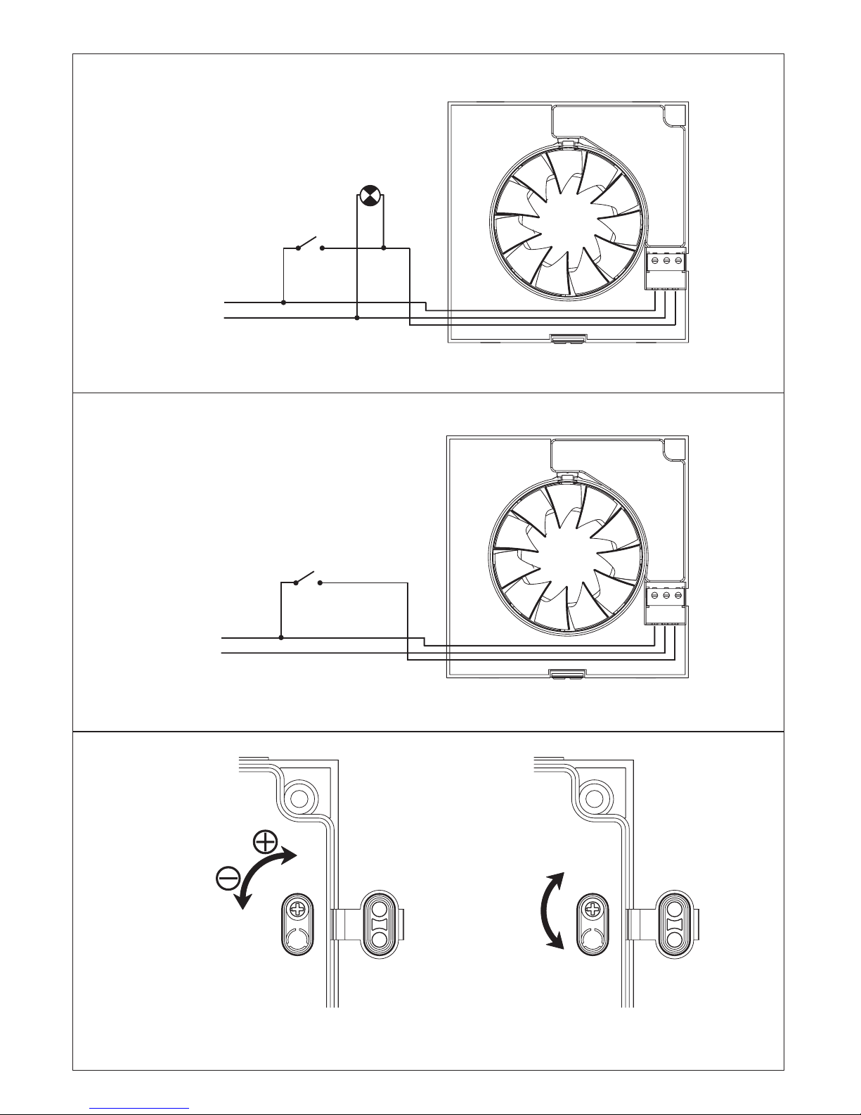
Fig.5
L
L
L
L
NNLs
NNLs
Fig.6
T (min)
SILENT-100 CRZ
Fig.7
DSILENT-100 C Z
T (min)
30
20
5
A
SILENT-100 CRIZ
Page 5
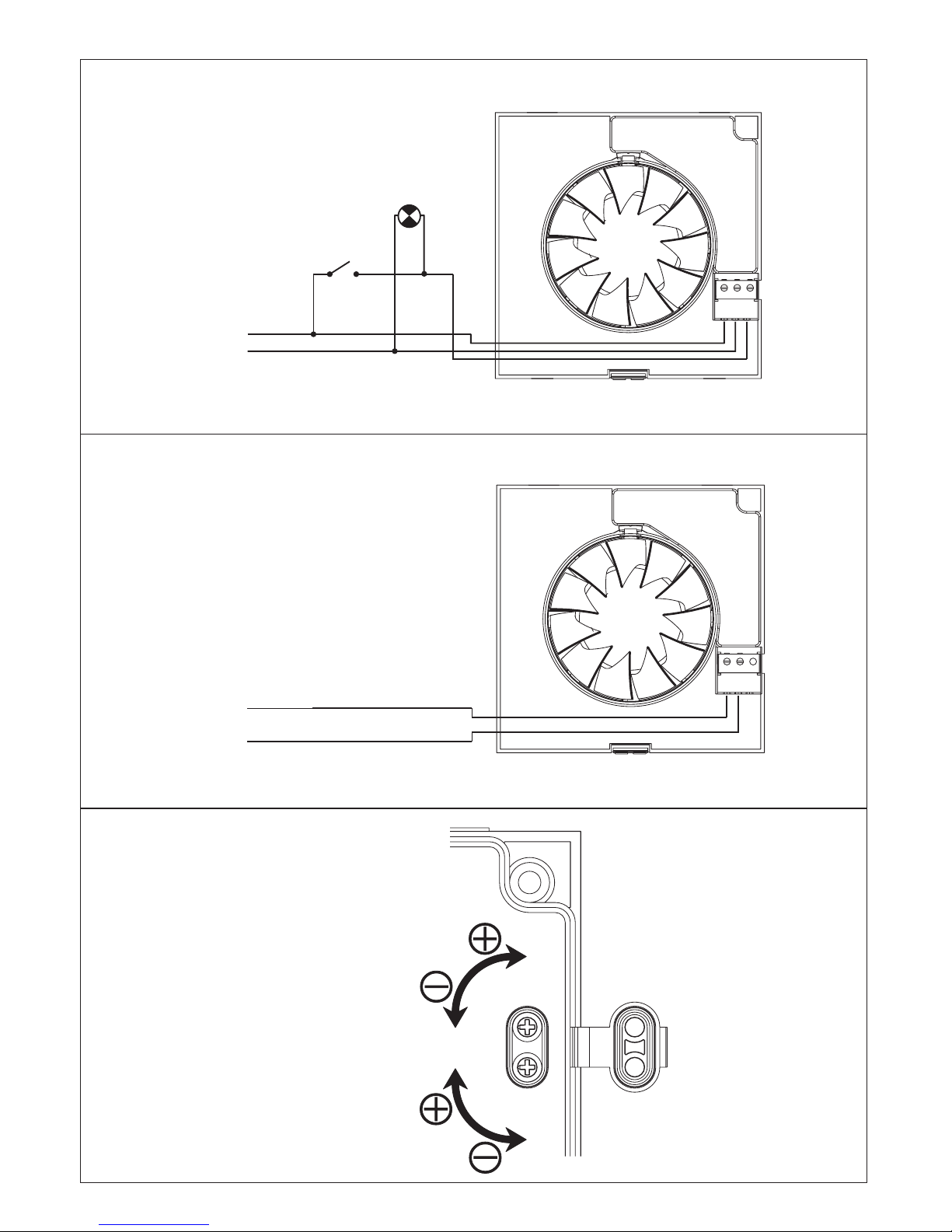
Fig.8
L
L
L
L
NNLs
NNLs
Fig.9
Fig.10
T (min)
HR (%)
Page 6

ENGLISH
SILENT-100 Axial Extractor Fans
The SILENT-100 extractor fan range is
manufactured to the high standards of
production and quality as laid down by the
international Quality Standard ISO 9001. All
components have been checked and every
one of the final products will have been
individually tested at the end of the
manufacturing process.
On reciept of the product we recommend that
you to check the following :
1- That it is the correct size.
2- That it is the correct model.
3- That the details on the rating label are
those you require: voltage, frequency ...
The installation must be carried out in
accordance with the electrical standards in
force in your country.
Installation
IMPORTANT
: Before installing and wiring
the unit, ensure that the main supply is
disconnected.
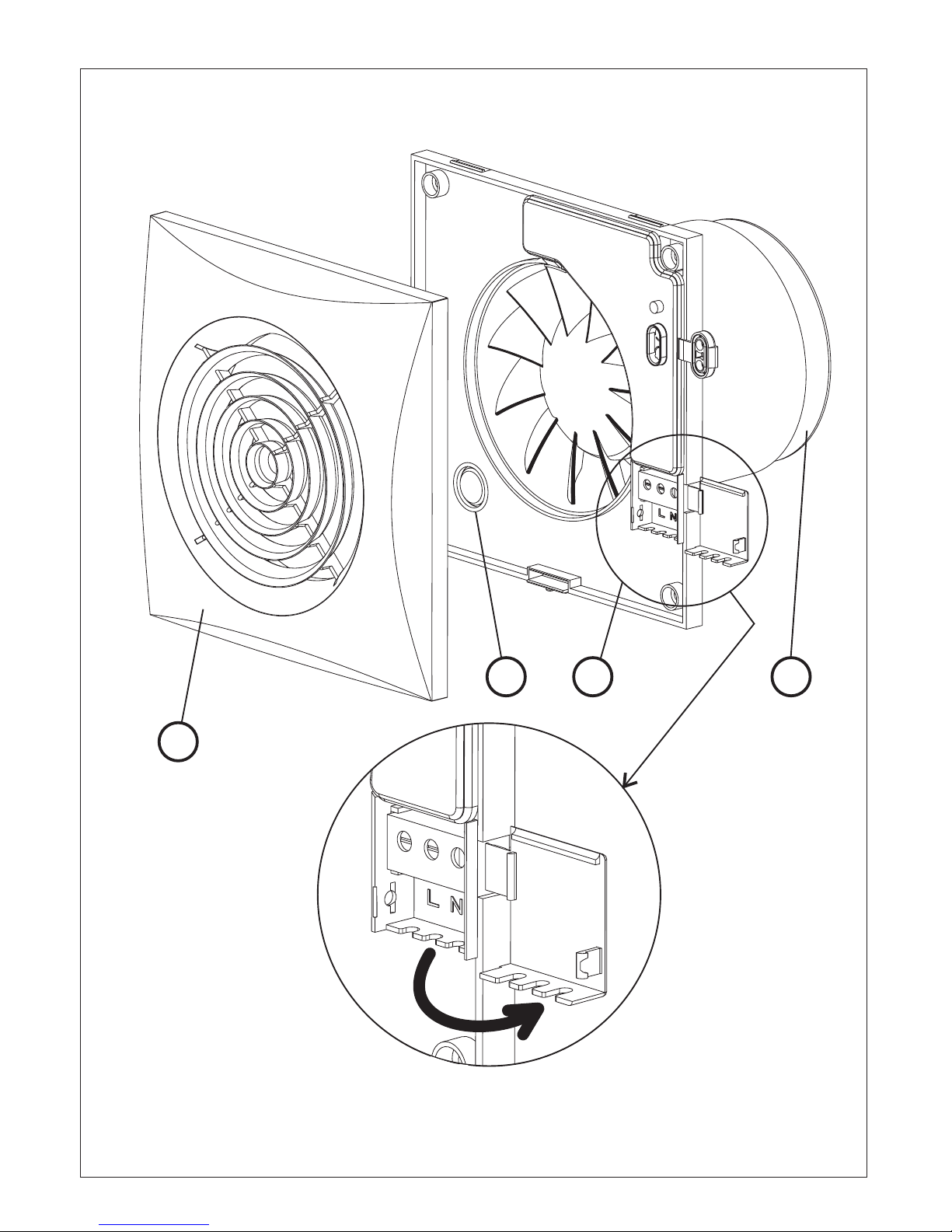
Fig. 1:
1: Protection grille
3: Outlet with backdraught shutter
2: Connection terminals
4: Cable entry
The SILENT-100 is suitable for wall or ceiling
mounting and can either discharge directly to
the outside or via an individual ducting
system (see Fig. 2).
The unit can be mounted on the wall or
ceiling using the 4 rubber blocks and the
screws provided.
Make a hole in the wall or ceiling of 105 mm
dia.
If the unit is to be installed with individual
ducting, use a standard 100 mm dia. duct.
Ensure that there are no obstructions to the
airflow and that the impeller turns freely.
Fix the extractor to the wall in such a way that
it is not distorted in order to avoid noise
generation or problems with the rotation of
the impeller. Make sure that the backdraught
shutter opens freely and has not being
damaged in transit. Introduce the mains
cable through the cable entry (4) and fix it to
the wall.
Connect the electrical wiring as set out below
and then mount the protection grille (1).
Electrical connection
The SILENT-100 is an extractor designed for
a single phase supply, with voltage and
frequency as indicated on the rating plate of
the unit. The units are manufactured with
double electrical insulation
(Class II) and therefore they do not need an
earth connection.
The electrical installation must include a
double pole switch with a contact clearance
of at least 3 mm.
TheelectricalcablemustentertheSILENT100 through the cable entry (4).
Once the cable has been introduced proceed
using the electrical wiring diagram applicable
to the selected model.
SILENT-100 CZ
For these models use the following
diagrams:
Fig.3: Switching the extractor through the
light switch.
Fig.4: To switch the fan through an
independent switch.
SILENT-100 CRZ
This model is provided with an adjustable
over-run timer. The timer allows the fan to
continue to operate for the selected period
after the switch has been turned off (fig.6).
Model provided with a 4 positions adjustable
electronic timer:Fig.5 shows how to connect
the fan with timer utilising the same switch as
for the lighting circuit.
To set the timer, turn the potentiometer on the
printed circuit board as (fig. 7).
- To reduce the "run on" time, turn
anticlockwise (min. 1 minutes)
- To increase the "run on" time , turn
clockwise (max: 30 minutes).
Page 7

SILENT-100 CRIZ
This model is provided with an adjustable
over-run timer. The timer allows the fan to
continue to operate for the selected period
after the switch has been turned off (fig.6).
ATTENTION: The product also includes
an over-run timer facility that starts the
fan after the first 50 seconds of nonoperation. After these first 50 seconds the
fan operates automatically.
Model provided with a 4 positions adjustable
electronic timer:Fig.5 shows how to connect
the fan with timer utilising the same switch as
for the lighting circuit.
To set the timer, turn the potentiometer on the
printed circuit board as (fig. 7).
Position Auto
:
If the period of operation is less than 50
seconds then the over-run timer will not
operate
If the period of operation is more than 50
seconds then the over-run timer will operate
in accordance to the period of operation
(period of operation x 2 with a maximum of
30 minutes).
Position 5'
Position 20'
Position 30'
: 5 minutes "run on" time
: 20 minutes "run on" time
: 30 minutes "run on" time
SILENT-100 CHZ
Models provided with an electronic
humidistat which can be adjusted from 60%
to 90 % RH (relative humidity) and with a
timer, adjustable between 2 and 20 minutes.
Operation
Case
1: Automatic operation (fig.9)
In automatic operation, the humidistat
causes the extractor to operate automatically
when the humidity level in the room is higher
than the set level. The extractor will stop
automatically when the humidity drops below
the selected level and after the selected
period set on the timer.
Case
2: Automatic operation as in case 1
with the facility to override the hygrostat by
means of the light switch (fig.8), when the
humidity level in the room is lower than the
selected level. In this case, the extractor
continues to operate for the selected period
set on the timer after the switch light has
been switched off.
ATENTION: When the himidity rate is
above the selected value, the automatic
option takes precedence over the manual
and the unit cannot then be switched off
using a switch.
The desired humidity level is selected by
means of a potentiometer “ ” positioned
%Hr
on the printed circuit board (fig.10) and
accessible once the grille (1) has been
removed.
- To increase the humidity setting turn
anticlockwise (min.60 %)
- To reduce the humidity setting turn
clockwise (max. 90 %)
To set the timer, turn the potentiometer “
” on the printed circuit board (fig.10):
min.
- To reduce the "run on" time, turn
anticlockwise (min. 2 minutes)
- To increase the "run on" time , turn
clockwise (max: 20 minutes).
SILENT-100 CDZ
Models provided with a PIR (passive
infra-red) detector. The unit starts
automatically when a movement is
detected with a maximum distance of 4
metres (fig.9).
They are also fitted with an adjustable
"run on" timer (1 to 30 minutes), and the
unit will continue to operate for the set
period after initiation by the movement
detector.
To set the temporisation, turn the
potentiometer on the printed board (fig.7):
- To reduce the "run on" time, turn
anticlockwise (min. 1 minute)
- To increase the "run on" time, turn
clockwise (max: 30 minutes).
t
Page 8

Maintenance
The extractor fan only requires periodical
cleaning using a cloth lightly impregnated
with a soft detergent.
After Sales Service
We recommend you not to try to dismantle or
remove any other parts than those
mentioned as any tampering would
automatically cancel the S&P guarantee. If
you detect any fault, contact your S&P
dealer.
S&P reserves the right to alter specifications without
notice
Page 9

Soler & Palau
Polígono Industrial Llevant
c/ Llevant, 4
08150 Parets del Vallès (Barcelona)
Spain
Tel. (34) - 93 571 93 00
Fax. (34) - 93 571 93 11
http://www.solerpalau.com
Ref. 0288170012
 Loading...