

Page 1
PM-755
PM-1005
PM-1505
PM-2005
Page 2
2
Page 3
ENGLISH
Please read these instructions thoroughly to avoid damage and hazardous situations. Any
use of this CONVECTOR HEATER other than that stipulated in this instruction manual may
cause fire, electric shock or injury, and voids all warranties.
Warranty does not apply to any defect, deterioration, loss, injury or damage caused by, or
as a result of, the misuse or abuse of this heater. the rights dictated by State law are not
prejudiced. None of the terms of this warranty are to be taken as excluding any conditions or
ENGLISH
warranties implied by State law, which cannot be excluded or modified.
Before any operation remove the packaging and check product integrity. In case of defects or
damages do not try to repair it yourself but contact your dealer.
Do not let children play with the packaging and protect the environment by disposing of the
packaging in accordance with the national regulations for waste processing.
1. SAFETY WARNINGS
1. This appliance has been designed as a radiation heater for wall
installation. It should be used as a source of heat and only for
this purpose.
2. The device should must not be positioned to operate in romos
or stores where a hazard can arise due to the presence of gases originating from paints, chemical products, detergents,
thinners, varnishes, etc., or other highly inflammable materials.
3. The device must be mounted on a solid, vertical wall, ensuring
that is perfectly levelled, both vertically and horizontally.
4. The device must not be mounted on a wall with an inflammable
surface, such as: wood, plastic, carpet, fibre, etc.
5. Make sure that the minimum safety distances are adhered to
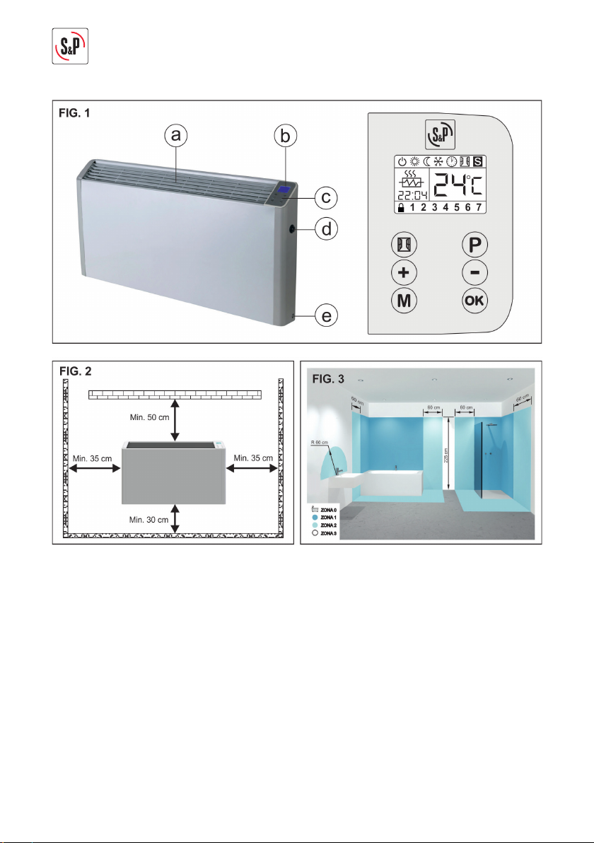
once installed. (See FIGURE 2)
6. WARNING; Once installed, no inflammable objects or objects
affected by heat should be within 1 metre of the device (curtains, furniture, towels, plants, pets… etc).
7. This device must not be installed in an enclosed place where
air cannot circulate freely, both at the entrance and the exit.
12
Page 4
8. Do not install the device immediately underneath a power socket.
9. For fixed electrical installation, disconnection means should
be included in accordance with installation regulations, with
contact separation at all poles that provides total disconnection under Category III overvoltage conditions.
10. This heater is Class II (double-insulated ) and therefore does
not require an earth connection.
11. The safety zones required by the local electrical installation
standards or safety regulations applicable in your country must
be strictly observed. In any case, if it is going to be installed in
a bathroom, NEVER install it in the area indicated as AREA 0,
AREA 1 or AREA 2. As it is an IP21 rated device, it can be installed in AREA 3, provided it is placed so that it is NOT in reach
of anybody who is in the bathtub or shower, this including the
device’s power cord. (See FIGURE 3).
12. CAUTION: Some parts of this device may get very hot and
cause severe burns. Special care must be taken when children
and vulnerable persons are present.
13. Before plugging in the device, make sure the mains voltage
matches that indicated on the data plate.
14. If the power cord is damaged, it should be replaced at one of
our official S&P Service Centers or by a qualified professional.
ENGLISH
15. To avoid overheating, DO NOT COVER the device.
16. Do not insert any rigid body through the bars, this could damage the device, start a fire or cause electric shock.
17. In humid rooms, the power cord must be at least 25 cm above
the ground. Make sure the cord doesn’t touch the ground.
18. Make sure the power cord doesn’t touch the hottest parts of
the device.
19. Children under 3 years old should be kept out of the reach of
the appliance unless they are continuously supervised.
20. Children under 8 years old may NOT operate the appliance.
13
Page 5
21. This device can be used by children from 8 years up and persons with reduced physical, sensory or mental capacities or
lack of experience and knowledge if they have been given the
appropriate supervision and training on using the device in a
safe way and understand the dangers involved.
22. Children should not play with the appliance.
23. Before carrying out any cleaning or maintenance operation,
make sure the device is unplugged from the mains.
24. The cleaning and maintenance to be done by the user must not
ENGLISH
be done by children.
25. Do not clean the device while it is working and do not immerse
it in water.
26. Do not handle the appliance with wet hands.
27. Device designed for internal use.
2. DESCRIPTION OF THE DEVICE / CONTROL PANEL (FIGURE 1)
a) Hot air outlet grille.
b) LCD control screen.
c) Control panel.
d) Main switch (ON / OFF).
e) Thermostat probe.
3. INSTALLATION (FIGURE 4)
CAUTION: Before installing the device, read all the Safety Warnings in the relevant section
of this manual carefully.
As far as possible, you should install this Wall Heater under a window, but never in a draughty
area.
3.1. With a Ø 6mm bit, drill the three holes (1-2-3) according to the measures indicated, then
insert the wall plugs (Fig. 4 A).
3.2. In the top two holes fix the hook-shaped wall supports (Fig. 4 A).
3.3. Hang the appliance on these supports and then secure it so it cannot come unfastened.
Insert the support in the central grooves of the bottom grille and fix it with the corresponding screw (Fig. 4B).
4. ELECTRICAL CONNECTION
CAUTION: Before connecting the device, check the supply voltage of the electricity network
matches the one stated on the type label of the device.
14
Page 6
4.1. The appliances have double electrical insulation , so they do not require ground con-
24
c
3
22:04
24
c
3
22:04
nection. The power cord has three connection wires, connect them as indicated in
Figure 5. The Brown – Blue wires are connected to the L – N of the electrical installation.
The black wire is used when we want to control several Wall Heaters by means of a Pilot
wire programmer (Important for France). If you don’t have a Pilot wire programmer,
leave the wire correctly insulated in the same plug without connecting it.
5. INSTRUCTIONS FOR USE
CAUTION: Before proceeding with the device’s instructions of use, read all the Safety Warnings in the relevant section of this manual carefully.
5.1. ON / OFF SWITCH
Press the main switch located on the side of the appliance (ON / OFF) to turn the appliance
on / off.
NOTE: If the appliance is not going to be used for a long period of time (summer), we recommend disconnecting it using this main switch.
5.2. DAY / TIME PROGRAMMING
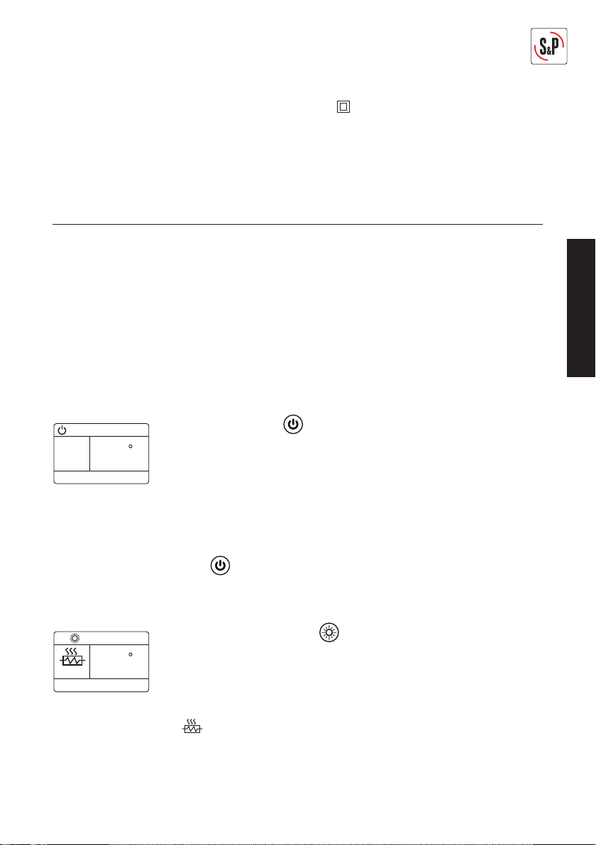
Press the (M) until the icon appears on the screen. Then press (OK)
to confirm. Next, press (OK) again for 3 seconds. The day of the week will
flash (1-Monday …. 7-Sunday) and we can adjust it pressing the (+) or (-)
buttons. We set the day pressing (OK) and do the same to adjust the hour
and minutes. Pressing (OK) to finish programming the time.
5.3. OPERATING MODES
ENGLISH
STANDBY mode
Press the (M) button until the icon appears on the screen. When this icon appears on the
screen, the appliance is not heating, it is in standby mode.
COMFORT mode
Press the (M) button until the icon appears on the screen.
Then press (OK) to confirm. The desired temperature in the room will
start to flash and we can adjust it by pressing the (+) or (-) buttons. We
confirm by pressing (OK) and the actual room temperature will appear
on the screen. If the actual room temperature is below the desired temperature, the wall heater will start heating, indicated on the screen with
the icon. If on the other hand the actual room temperature is above
the desired temperature, the appliance will stay in standby mode.
NOTE: If it is a day room (dining room / living room) we recommend setting the thermostat
at +22/+23 ºC.
15
Page 7
ECONOMY mode (ECO).
18
c
3
22:04
5
c
3
22:04
1
1 2 3 4 5 6 7
00:00
1
Press the (M) button until the icon appears on the screen.
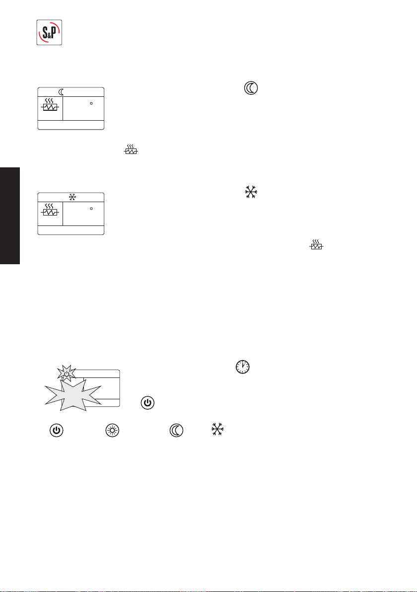
Then press (OK) to confirm. ECO mode is factory-set, so the room temperature is 18ºC (this cannot be changed). We confirm pressing (OK) and
the actual room temperature will appear on the screen.
If the actual room temperature is below +18ºC, the wall heater will start heating, indicated
on the screen with the icon. If on the other hand the actual room temperature is above
+18ºC, the appliance will stay in standby mode.
DEFROST mode
ENGLISH
NOTE: This operating mode is very useful when we are going to be away for a few days or for
second homes, and we don’t want the house temperature to fall below +5ºC with the risk of
the water pipes icing up.
5.4. AUTOMATIC OPERATION
We can set the desired operating mode for the seven days of the week, with half-hour time
bands.
•
Press the (P) button and the icon appears on the screen, press
• With the (M) button we can define the desired operating mode for the day’s time distances:
( Standby // COMFORT // ECO // DEFROST).
• With the (+) and (-) buttons you can define the operating time bands for each mode (Half-
hour bands).
Press the (M) button until the icon appears on the screen.
Then press (OK) to confirm. Defrost mode is factory-set, so the room
temperature never falls below +5ºC (this cannot be changed). We confirm by pressing (OK) and the actual room temperature will appear on
the screen. If the actual room temperature is below +5ºC, the wall heater
will start heating, indicated on the screen with the icon. If on the
other hand the actual room temperature is above +5ºC, the appliance
will stay in standby mode.
(P) again for 3 seconds to get into the weekly program. The 7 days of
the week will light up, only the day (1-Monday), the time 00:00 and
the icon flashing.
NOTE: Every time we change operating mode, the informative number of changes we are
programming for each day on the screen increases. So, every day we can set 48 different
operating modes, one for each ½ hour of the day.
At the end of the day (23:30), press (OK) for 5 seconds to skip to the next day and set the operating modes again for this day.
IMPORTANT: If we want to copy the same program as the previous day, so as not to have to
repeat the entire operation, we press the (OK) button again for 5 seconds and copy the program from the previous day and skip to the next.
16
Page 8
When we have finished setting Sunday (7) at 23:30, we save the weekly program entered,
pressing the (P) button.
The device will execute the weekly program, provided we have the icon activated on the
screen. The screen will indicate what operating mode is running for each ½ hour of the day.
5.5. OPEN WINDOW DETECTION
To avoid the heater working with the window open, the heater incorporates an energy saving
control function.
Press to activate / deactivate this function. The corresponding icon will come up on the
screen to indicate the control feature has been activated.
• If the room temperature falls 5ºC in 10 minutes, the heater detects that we have a window /
door open and the heater will stop working for 60 minutes. On screen the open window icon
will flash to inform us that this function is active.
If after the 60 minutes the temperature still hasn’t risen at least 1ºC, the heater will stay off
for another 60 minutes, as it understands that the window / door is still open.
• If the temperature of the room has increased one degree with respect to the temperature
prior to the 60 minutes it has been turned off, the heater will continue to work in the previous operating mode.
• We can always deactivate the feature by pressing again.
NOTE: This feature does not activate if we have DEFROST operated mode activated.
5.6. LOCKING SYSTEM
• This option is very useful for public places such as libraries, hotels, etc., where we don’t
want anyone to be able to manipulate the WALL HEATER. By activating this feature, the
appliance will work in the mode we have set and nobody will be able to manipulate the
controls.
Press the (+) and (-) buttons simultaneously for 5 seconds to activate/deactivate the
appliance’s locking system. When it is locked, the icon will appear on the screen.
• Even if the heater is switched off by pressing the main switch or by unplugging it from the
mains, the locking system remains saved.
ENGLISH
5.7. PILOT-WIRE PROGRAMMER
Connect the signal with the remote pilot wire programmer (4 orders) Long press OK button
6s, you will hear the “Bi” sound and the machine is already connected with the remote programmer (to ensure that the programmer 4 order has been connected and can work well),
LCD screen display icon (slaver) as well as working status, clock and ambient temperature.
If disconnect the remote programmer, long press OK button 6S, you will hear 3 “Bi” sound,
then, the machine will setback to the “Stand By” mode.
Attention: When the machine is set with the remote pilot wire programmer, only OK button
still workable, others button do not work.
17
Page 9
5.8. ERROR MESSAGE
If the error message (E1) appears on the screen, please contact the After Sale Services Network if in Spain or your usual dealer in the rest of the world. To fi nd out where this is, you can
go to the WEBSITE: www.solerpalau.com
6. MAINTENANCE
Before starting any maintenance operation don’t forget to let the device cool down for a few
minutes and unplug it from the mains.
• This product requires regular cleaning (at least once a year) to avoid dust build-up at the
rear (air inlet), as this could cause overheating.
• Unhook the device from the wall and clean the dust built up at the air inlet with a vacuum
ENGLISH
cleaner.
• Clean the body of the device with a wet cloth. Do not use detergents or other abrasive pro-
duct that could damage the finish / colour of the plastic.
• Do not immerse the device or spray water onto it.
7. TAKING IT OUT OF SERVICE / RECYCLING
EEC legislation and our consideration of future generations mean that we should
always recycle materials where possible; please do not forget to deposit all packaging in the appropriate recycling bins. If your device is also labeled with this
symbol, please take it to the nearest Waste Management Plant at the end of its
servicable life.
8. RELEVANT INFORMATION FOR THE DISMANTLING,
RECYCLING OR DISPOSAL OF THE PRODUCT AT THE END OF ITS OPERATING LIFE
If the appliance is scrapped, the necessary provisions for the disposal or recycling of the
materials and components must be followed.
List of the main materials in the WALL HEATER:
• Iron panel body and grille.
• PP V0 plastic sides.
• Electronic tin plates.
• Electrical copper cables.
• Tube resistor with aluminium fins.
9. TECHNICAL ASSISTANCE
S&P’s large Technical Service network will guarantee adequate technical assistance.
If a fault is observed in the unit, please contact any of the mentioned technical service offices
and they will attend to your problem.
Any manipulation of the appliance by personnel not belonging to the Official S&P Services will
result in your guarantee being void.
For any queries regarding S&P products please contact any branch of our After Sales Service
network if you are in Spain, or your regular dealer in the rest of the world. To find your nearest
dealer, visit our website at www.solerpalau.com
18
Page 10
S&P SISTEMAS DE VENTILACIÓN, S.L.U.
C. Llevant, 4
Polígono Industrial Llevant
08150 Parets del Vallès
Barcelona - España
Tel. +34 93 571 93 00
Fax +34 93 571 93 01
www.solerpalau.com
Ref. 1441343
 Loading...