

Page 1
Installation, Operation, and Maintenance Manual
READ AND SAVE THESE INSTRUCTIONS
The purpose of this manual is to aid in the proper installation and operation of fans
manufactured by S&P USA. These instructions are intended to supplement good
general practices and are not intended to cover detailed instruction procedures,
because of the wide variety and types of fans manufactured by S&P USA.
Installation, Operation, and Maintenance Manual
READ AND SAVE THESE INSTRUCTIONS
The purpose of this manual is to aid in the proper installation and operation of fans
manufactured by S&P USA. These instructions are intended to supplement good
general practices and are not intended to cover detailed instruction procedures,
because of the wide variety and types of fans manufactured by S&P USA.
6393 Powers Ave
Jacksonville, FL 32217
P: 800.961.7370
F: 800.961.7379
PCD80XH
PCD80XH-IOM_v.1-1118
Page 2

Page 3
Installation Instructions
PCD80XH
1. WARNING
TO REDUCE THE RISK OF FIRE, ELECTRIC SHOCK OR INJURY, OBSERVE THE FOLLOWING:
1. Before servicing or cleaning unit, switch power o at service panel and lock the service
disconnecting means to prevent power from being switched on accidentally. When the service
disconnecting means cannot be locked, securely fasten a prominent warning device, such as
a tag, to the service panel.
2. Installation work and electrical wiring must be done by a qualied person(s) in accordance with
all applicable codes and standards, including re-rated construction codes and standards.
3. Sucient air is needed for proper combustion and exhausting of gases through the ue
(chimney) of fuel burning equipment to prevent back drafting. Follow the heating equipment
manufacturer’s guideline and safety standards such as those published by the National Fire
Protection Association (NFPA), and the American Society for Heating, Refrigeration and Air
Conditioning Engineers (ASHRAE), and the local code authorities.
4. When cutting or drilling into wall or ceiling, do not damage electrical wiring and other hidden
utilities.
5. Ducted fans must always be vented to the outdoors.
6. Acceptable for use over a tub or shower when connected to a GFCI (Ground Fault Circuit
Interrupter) - protected branch circuit (ceiling installation only).
7. This unit must be grounded.
CAUTION
1. For general ventilation use only. Do not use to exhaust hazardous or explosive materials and
vapors.
2. This product is designed for installation in ceilings up to a 12/12 pitch (45° degree angle). Duct
connector must point upwards.
3. To avoid motor bearing damage and noisy and/or unbalanced impellers, keep drywall spray,
construction dust, etc. o power unit.
4. Please read specication label on product for further information and requirements.
*The manual in electronic format can be downloaded on our website, or obtained from our dealer.
2. CLEANING & MAINTENANCE
For quiet and ecient operation, long life, and attractive appearance - lower or remove grille and
vacuum interior of unit with the dusting brush attachment. The motor is permanently lubricated and
never needs oiling. If the motor bearings are making excessive or unusual noises, replace the motor
with the exact service motor. The impeller should also be replaced.
3. OPERATION
See “Connect Wiring Diagram” for details.
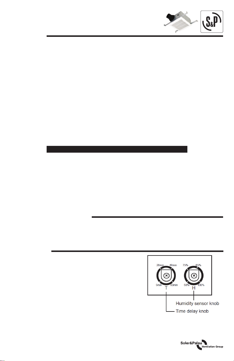
1. Turn ON switch I, fan run continuously at the default
low speed (40 CFM) and automatically boost up to high
speed (80 CFM) when either of these conditions is
detected:
(a) Humidity above a user-adjustable set point (50%-
100% relative humidity).
(b) Rapid to moderate (user-adjustable) increases in
humidity. After delay timer (adjustable from 5 to 60
mins) returns fan to the default low speed. Humidity
sensor description according to “HUMIDITY SENSOR
OPERATION” and “SENSITIVITY ADJUSTMENT”.
When switch II is turned ON, the fan changes to high speed. When switch II is turned OFF, fan
will continue to run at the high speed until the delay timer has elapsed, and then will automatically
change to low speed.
1
Page 4
HUMIDITY SENSOR OPERATION
The humidity-sensing fan uses a sophisticated humidity sensor that responds to:
(a) rapid to moderate (user-adjustable) increases in humidity, or (b) humidity above a
user-adjustable set-point (50%-100% relative humidity). The fan runs continuously at a
pre-set lower level (set by humidity sensor knob) and automatically boosts up to a certied
airow rate when environmental conditions change). If the fan continuously responds to changing
environmental conditions, “H” (means “humidity”) adjustment may be required. This gure is factory-set
for about 75% (ambient temperature of 77°ᶠ/25°ᶜ).
SENSITIVITY ADJUSTMENT
The “H” has been factory-set for most shower applications. However, if the fan is in a tub area or is
being used for dampness control, the “H” may need to be increased toward maximum “+”. If the control
is responding too often to changing environmental conditions, movement toward less “-”, “H” may be
required.
To adjust the “H” :
1. Disconnect power at service entrance.
2. Through the grille, locate the slot marked “H”.
3. Carefully rotate the “H” adjustment toward “+” or “-”.
4. Turn on power and check operation by turning on the shower or other humidity source until
the fan turns on.
5. Repeat above steps if necessary.
When the temperature changes, humidity sensor values will have deviation.
4. PLAN THE INSTALLATION
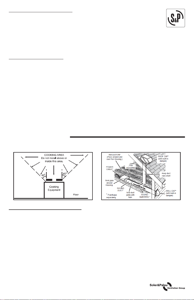
1. Do not use in a cooking area.
2. Two ways to connect duct work to a factory-shipped unit.
TYPES OF TYPICAL INSTALLATIONS
1. Housing mounted to I-joists (Start at “ASSEMBLY INSTRUCTIONS 1”).
2. Housing mounted to joists (Start at “ASSEMBLY INSTRUCTIONS 1” ).
3. Housing mounted to truss (Start at step “ASSEMBLY INSTRUCTIONS 2”).
2
Page 5
5. ASSEMBLY INSTRUCTIONS
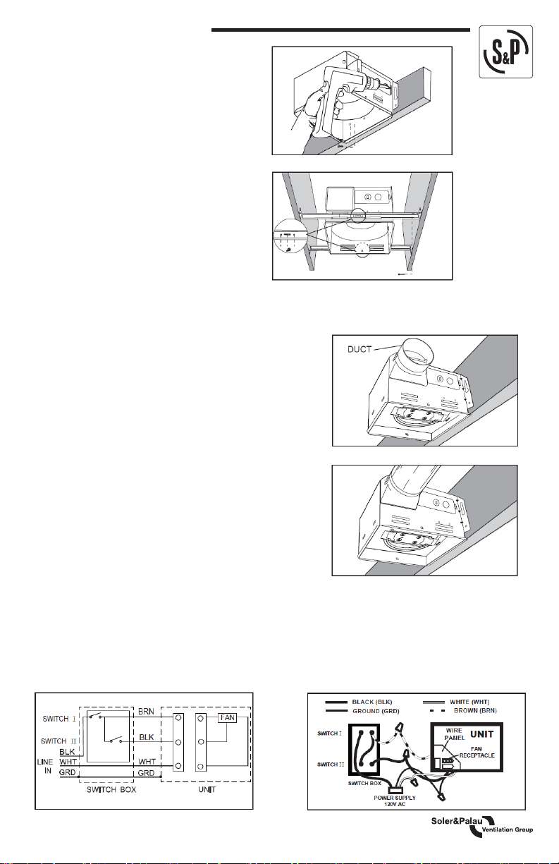
1. Mount Housing to Joist of I-Joist
Hold the housing so that it is in contact with the
bottom of the joist. Place the fan housing next
to the ceiling joist. Using wood screws, attach
the housing loosely to the ceiling joist through
the keyholes in the mounting tabs. Adjust the
housing to be ush with the nished ceiling. For
the grille to t properly, the housing’s rim must
not extend beyond the nished ceiling surface.
When the housing is correctly adjusted, tighten
the screws in the slots.
2. Mount With Hanger Bars
Insert the hanger bars into the slots in the
housing. Place the fan housing between the
joists, make sure the bottom of the housing is
even with the nished ceiling. Extend the hanger
bars to the joist. Use screws to secure the
hanger bars to the ceiling joists. Select a proper
hole and secure the hanger bars together using
ange screws.
3. Attach Damper/Duct Connector
Snap the damper/duct connector onto the fan housing. The
connector must be ush with the top of the housing, and the
damper ap should fall closed.
4. Install Round Ductwork
Connect the round ductwork (not included) to the damper/
duct connector, and run the ductwork to a roof or wall cap
(not included). Using tape (not included), secure all the
ductwork connections so that they are air tight. Insulated
exible duct is recommended for the quietest possible
installation. If rigid duct is used, a short (1-3 feet) section of
insulated exible duct will ensure quiet operation.
Power Supply Jumper
The ducting from this fan to the outside of the building has
a strong eect on the air ow, noise, and energy use of the
fan. Use the shortest, straightest duct routing possible for
best performance, and avoid installing the fan with smaller
ducts than recommended. Insulation around the ducts can
reduce energy loss and inhibit mold growth. Fans installed
with existing ducts may not achieve their rated air ow.
5. Connect Electrical Wiring
Run 120V AC house wiring to the location of the fan. Use only UL-approved connectors (not included)
to attach the house wiring to the wiring plate. Refer to the wiring diagram below, and connect the wires
as shown.
3
Page 6
6. Install Grille
Install ceiling material to complete the ceiling
construction and cut around the fan housing.
To attach the grille assembly to the fan housing,
pinch the grille springs on the sides of the grille
assembly and position the grille into the housing
with the grille springs in the appropriate slots.
Push the grille assembly towards the ceiling to
secure.
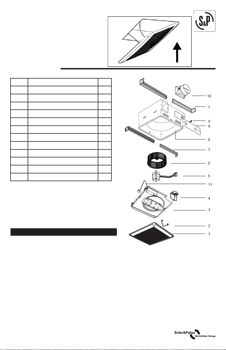
6. SERVICE PARTS
PART PART NAME Qty.
1 Grille Assembly (includes part 2) 1
2 Grille Spring 2
3 Motor Plate 1
4 Wire Panel / Harness Assembly 1
5 Motor 1
6 Blower Wheel 1
7 Hanger Bars 4
8 Housing 1
9 Wiring Plate 1
10 Damper / Duct Connector 1
11 Power Box 1
a Screw 1
* Blower Assembly includes part 5 & 6.
Replacement Installation:
Remove the screw on motor plate (part 3), then take
out the motor plate (part 3) from the housing (part 8)
by pushing down the rib in the plate while pulling out
on the side of the housing. Replace the broken parts.
WARNING
Ensure that the fan is switched o from the supply
mains before replacing.
4
Page 7

7. WARRANTY
S&P USA - S&P Canada warrant that the PCD80XH will be free from defective materials
and workmanship for the period of (5) years from the date of original purchase. In the
event that we nd any part is defective the product will be repaired or, in the Company’s
discretion, replaced without charge provided that the product has been installed in
accordance with the enclosed instructions and all applicable EPA Standards and state and local
building codes.
IF CLAIMING UNDER WARRANTY: Please return the complete product, freight paid, to your local
authorized distributor. All returns must be accompanied by a valid Bill Of Sale. All returns must be
clearly marked “Warranty Claim,” with an accompanying description stating the nature of the fault.
THE FOLLOWING WARRANTIES DO NO APPLY: Damages from shipping, either concealed or
visible. Claim must be led with the carrier. Damages resulting from improper wiring or installation
Damages caused by acts of nature, or resulting from improper consumer procedures such as: Improper
Maintenance; Misuse; Negligence; Alteration; Abuse; Abnormal Use; or Accident or Incorrect Electrical
Voltage and Current. Removal or alteration to the S&P USA - S&P Canada data plate label.
WARRANTY VALIDATION: The end user must keep a copy of the Bill of Sale to verify purchase date.
THE ABOVE (5) YEAR WARRANTY IS EXPRESSLY IN LIEU OF ALL OTHER WARRANTIES,
EXPRESSED, WRITTEN OR IMPLIED, INCLUDING THE WARRANTIES OF MERCHANTABILITY
AND FITNESS FOR USE. IN NO EVENT SHALL SOLER & PALAU USA - SOLER & PALAU CANADA
BE LIABLE FOR ANY SPECIAL, CONSEQUENTIAL, OR INCIDENTAL DAMAGES, INCLUDING
LOSS OF PROPERTY, REVENUES, LOST PROFITS, COSTS OF REMOVAL, INSTALLATION OR
REINSTALLATION.
5
Page 8
 Loading...