

Page 1
WARNING
READ AND SAVE THESE INSTRUCTIONS
Installer: Leave this manual with the homeowner.
CAUTION
CLEANING & MAINTENANCE
OPERATION
PLAN THE INSTALLATION
TO REDUCE THE RISK OF FIRE, ELECTRIC SHOCK, OR INJURY TO PERSONS, OBSERVE THE FOLLOWING:
1. Use this unit only in the manner intended by the manufacturer. If you have questions, contact the manufacturer at the
address or telephone number listed in the warranty.
2. Before servicing or cleaning unit, switch power off at service panel and lock the service disconnecting means to prevent
power from being switched on accidentally. When the service disconnecting means cannot be locked, securely fasten
a prominent warning device, such as a tag, to the service panel.
3. Installation work and electrical wiring must be done by a qualified person(s) in accordance with all applicable codes and
standards, including fire-rated construction codes and standards.
4. Sufficient air is needed for proper combustion and exhausting of gases through the flue (chimney) of fuel burning equip ment to prevent backdrafting. Follow the heating equipment manufacturer’s guideline and safety standards such as those
published by the National Fire Protection Association (NFPA), and the American Society for Heating, Refrigeration and
Air Conditioning Engineers (ASHRAE), and the local code authorities.
5. When cutting or drilling into wall or ceiling, do not damage electrical wiring and other hidden utilities.
6. Ducted fans must always be vented to the outdoors.
7. Acceptable for use over a tub or shower when connected to a GFCI (Ground Fault Circuit Interrupter) - protected branch
circuit (ceiling installation only).
8. This unit must be grounded.
1. For general ventilating use only. Do not use to exhaust hazardous or explosive materials and vapors.
2. This product is designed for installation in ceilings up to a 12/12 pitch (45 degree angle). Duct connector must point up.
DO NOT MOUNT THIS PRODUCT IN A WALL.
3. To avoid motor bearing damage and noisy and/or unbalanced impellers, keep drywall spray, construction dust, etc. off
power unit.
4. Please read specification label on product for further information and requirements.
For quiet and efficient operation, long life, and attractive appearance - lower or remove grille and vacuum interior of unit
with the dusting brush attachment.
The motor is permanently lubricated and never needs oiling. If the motor bearings are making excessive or unusual noises, replace the motor with the exact service motor. The impeller should also be replaced.
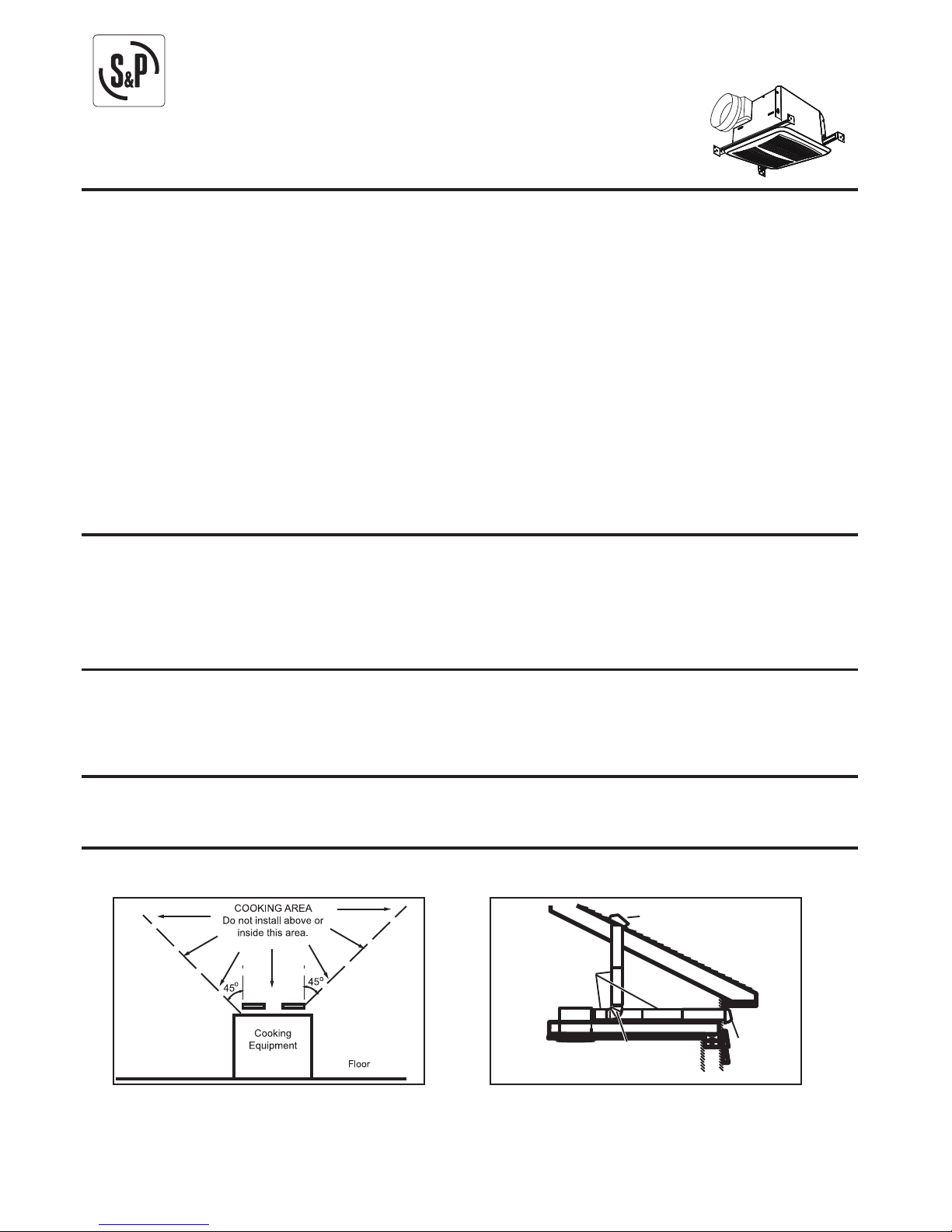
1. Do not use in a cooking area.
2. Two ways to connect ductwork to a factory-shipped unit.
*Purchase
separately
ROUND
ELBOW *
ROUND
DUCT *
ROOF CAP *
WALL
CAP *
Use an on/off switch to operate this fan. See “Connect Wiring Diagram” for details.
VENTILATION FAN
MODEL: PC80X PC110X
PC150
Page 2
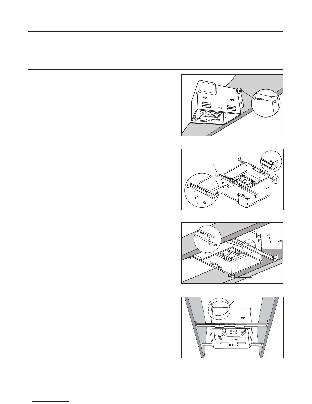
Hold the housing so that it is in contact with the bottom of the joist. Attach
the housing with four (4) screws to the joist through the holes in each
mounting flange.
1. MOUNT HOUSING TO JOIST OR I-JOIST.
HANGER
BAR
NAIL
2. MOUNT WITH HANGER BARS
2a. Sliding hanger bars have been provided, which allow the housing to
be positioned accurately anywhere between the framing. The bars span
up to 24 in. and can be used on all types of framing: I-joist, standard joist,
and truss construction. Slide hanger bars onto housing and adjust as
needed to fit between framing.
2b. Extend the hanger bars to the width of the framing. Position the
ventilator with the hanger bar tabs wrapped around the bottom edge of
the framing, holding the ventilator in place.
Secure hanger bars to framing using one screw on each end of hanger bar.
Select a proper hole and secure the hanger bars together using flange
screws.
3. ATTACH DAMPER/DUCT CONNECTOR
Snap the damper/duct connector onto the fan housing. The connector
must be flush with the top of the housing, and the damper flap should
fall closed.
TYPES OF TYPICAL INSTALLATIONS
ASSEMBLY INSTRUCTIONS
1. Housing mounted to I-joists (Start at “ASSEMBLY INSTRUCTIONS 1”)
2. Housing mounted to joists (Start at “ASSEMBLY INSTRUCTIONS 1” )
3. Housing mounted to truss (Start at step “ASSEMBLY INSTRUCTIONS 2”)
SCREW
2
DUCT
Page 3
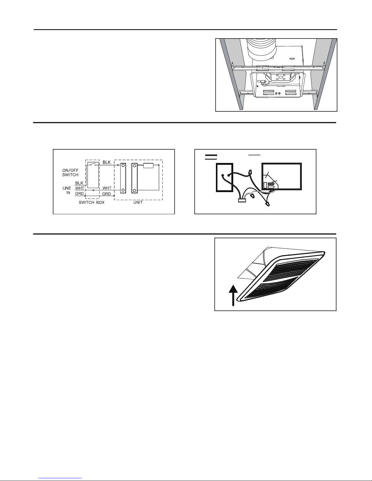
4. INSTALL ROUND DUCTWORK
Connect the round ductwork (not included) to the damper/duct connector,
and run the ductwork to a roof or wall cap (not included). Using tape (not
included), secure all the ductwork connections so that they are air tight.
Run 120 V AC house wiring to the location of the fan. Use only UL-approved connectors (not included) to attach the house wiring to the
wiring plate. Refer to the wiring diagram, and connect the wires as shown.
Install ceiling material to complete the ceiling construction and cut around
the fan housing.
To attach the grille assembly to the fan housing, pinch the grille springs on
the sides of the grille assembly and position the grille into the housing with
the grille springs in the appropriate slots. Push the grille assembly towards
the ceiling to secure.
ASSEMBLY INSTRUCTIONS
CONNECT ELECTRICAL WIRING
INSTALL GRILLE
3
UNIT
BLACK
SWITCH BOX
FAN
POWER SUPPLY
120V AC
GROUND (BARE)
WHITE
WIRING
PLATE
FAN
RECEPTACLE
FAN
Page 4
WARRANTY
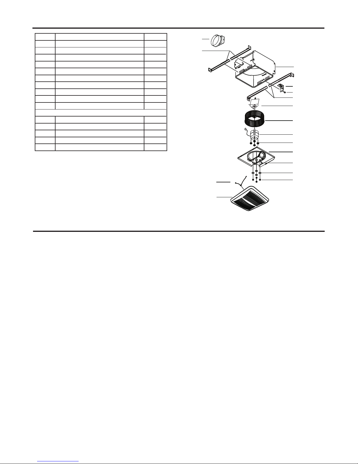
SERVICE PARTS
4
4
5
d
e
a
1
2
3
b
c
6
8
7
9
9
10
PART PART NAME Qty.
1
2
3
4
5
6
7
8
9
10
a
b
c
d
e
Housing
Damper / Duct Connector
Wiring plate
Screw
Blower Wheel
Wire Panel / Harness Assembly
Motor
1
2
1
1
1
1
1
1
4
1
4
4
1
4
1
Isolator
Motor Plate
Washer
Nut, Hex Lock
Grille Assembly (includes part 2)
Grille Spring
Hanger Bar Kit
Screw
* Blower Assembly includes part 5, 4, d, 3, c, b, a.
Replacement installation:
Remove the screw (part c), then take out the motor plate (part 3) from
the housing (part 8) by pushing down the rib in the plate while pulling
out on the side of the housing. Replace the broken parts.
WARNING: Before replacing, be sure to turn off power at power source.
S&P USA Ventilation Systems, LLC & S&P Canada Ventilation Systems, Inc. (S&P) warrants to the original end user of its
products that our exhaust fans will be free from defects in materials and workmanship for a period of Five (5) years from
the date of original purchase. THERE ARE NO OTHER WARRANTIES, EXPRESSED OR IMPLIED, INCLUDING BUT
NOT LIMITED TO IMPLIED WARRANTIES OF SUITABILITY FOR A PARTICULAR PURPOSE.
During this five year period, S&P will, at its option, repair returned products or parts, or provide replacement products or
parts, without charge, for any product or part which is found to be defective under normal use.
This warranty does not cover normal maintenance and service or any parts that have been subject to misuse, negligence,
accident, improper maintenance or repair, faulty installation or installation contrary to recommended installation instructions.
S&P’s obligation to repair or replace, at S&P’s option, shall be the purchaser’s sole and exclusive remedy under this
warranty. No labor or materials are covered by this warranty. S&P shall not be liable for incidental damages arising out of
or in connection with product use or performance.
This warranty gives you specific legal rights. You may also have other rights which vary from state to state.
To qualify for warranty service, you must notify S&P at the address or telephone number stated below, provide the model
number and part identification, and describe the nature of any defect in product or part. You may be required to ship a
defective part to S&P. There will be no charge for shipping repaired or replacement parts from S&P to you if your address
is in the United States or Canada. At the time of requesting warranty service, you must present evidence of the original
purchase date.
S&P USA Ventilation Systems,LLC
6393 Powers Avenue Jacksonville, FL 32217
P. 904-731-4711
F. 904-731-8322
www.spvg-northamerica.com
S&P Canada Ventilation Products, Inc
5600 Ambler Drive Mississauga, ON L4W 2K9
P. 866-733-0233
F. 866-358-5346
www.solerpalaucanada.com
 Loading...