

Page 1

INSTALLATION, OPERATION &
MAINTENANCE INSTRUCTIONS
MD DEHUMIDIFIERS
QA/IOM/46 Issue 11 - MD Dehumidifier
Page 2

Contents: page
1. General description 3
1.1. General 5
1.2. Refrigeration system 5
1.3. Fan and ventilation system 6
1.4. Safety features 6
1.5. Performance 7
2. Preparation of dehumidifier from delivery 8
3. General operating instructions 9
3.1. Siting of the dehumidifier 9
3.2. Changing from pump to gravity condensate discharge 10
3.3. Fan only / dehumidifying (modes of operation) 10
3.4. Fan speed operation 11
4. Installation wiring 11
5. Control panel 15
6. Maintenance and fault finding 15
6.1. Maintenance 15
6.2. Faults 16
6.3. Technical support 17
7. Spares list 17
7.1. Electrical 17
7.2. Refrigeration/ mechanical 17
8. Contact Information 18
QA/IOM/46 Issue 11 - MD Dehumidifier
Page 3
1. GENERAL DESCRIPTION
The dehumidifier is based around a closed refrigeration system comprising evaporator coil,
condenser coil, expansion valve and compressor. It uses heat pipes to increase the cooling
efficiency, allowing more moisture to be extracted, compared to conventional dehumidifiers. A fan is
used to draw air inthrough a filter and across the evaporatorand discharge it through the condenser.
Moisture is removed from the entering humid air at the evaporator coil and it is collected in a drain
pan mounted below the coil. The collected condensate is then removed by an integral condensate
pump.
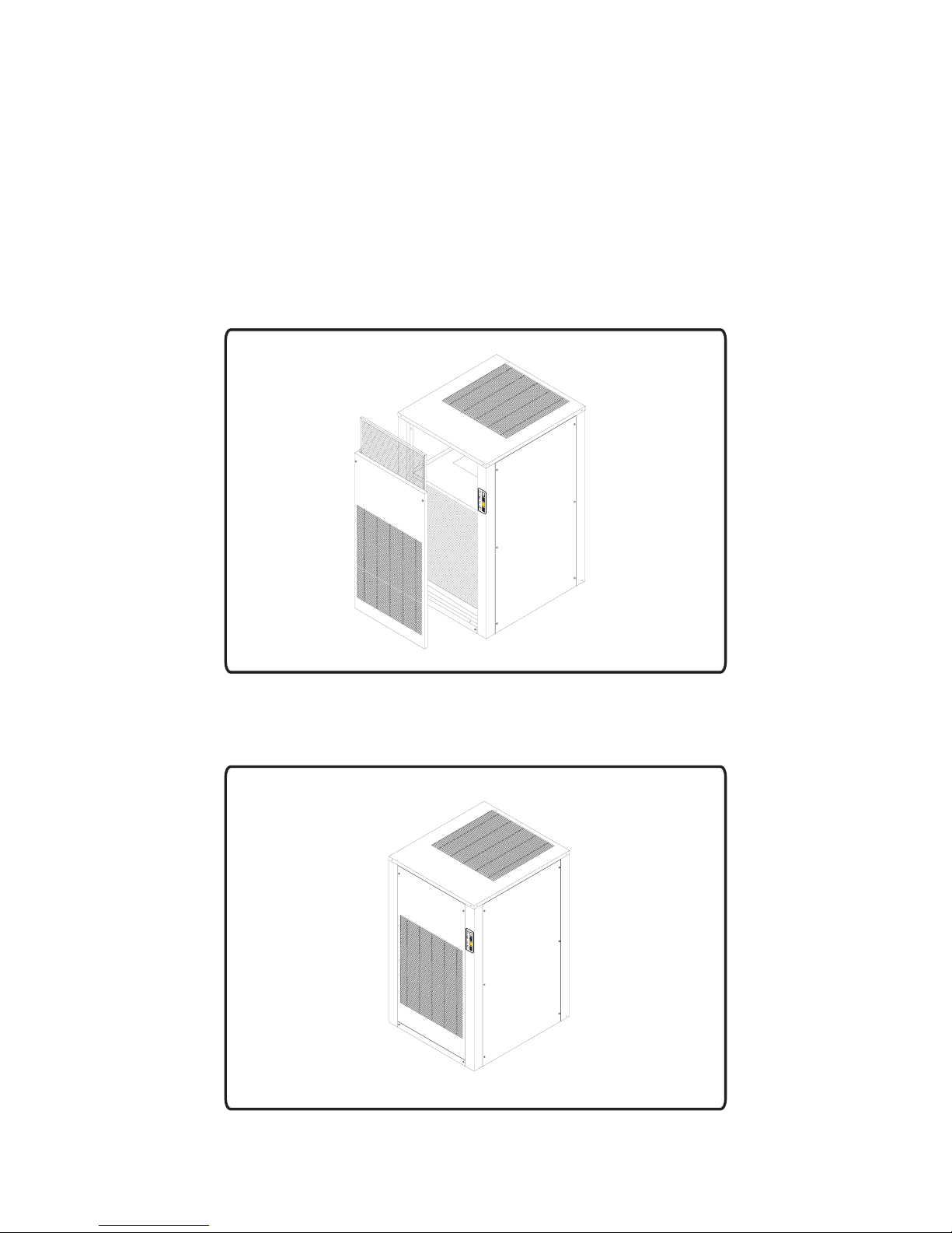
Figures 1. to 4. Showthe general layout of the dehumidifiers externallyand internally.
Figure 1. General layout of MD units with front grille removed
Figure 2. General layout of MD units
QA/IOM/46 Issue 11 - MD Dehumidifier
Page 3
Page 4
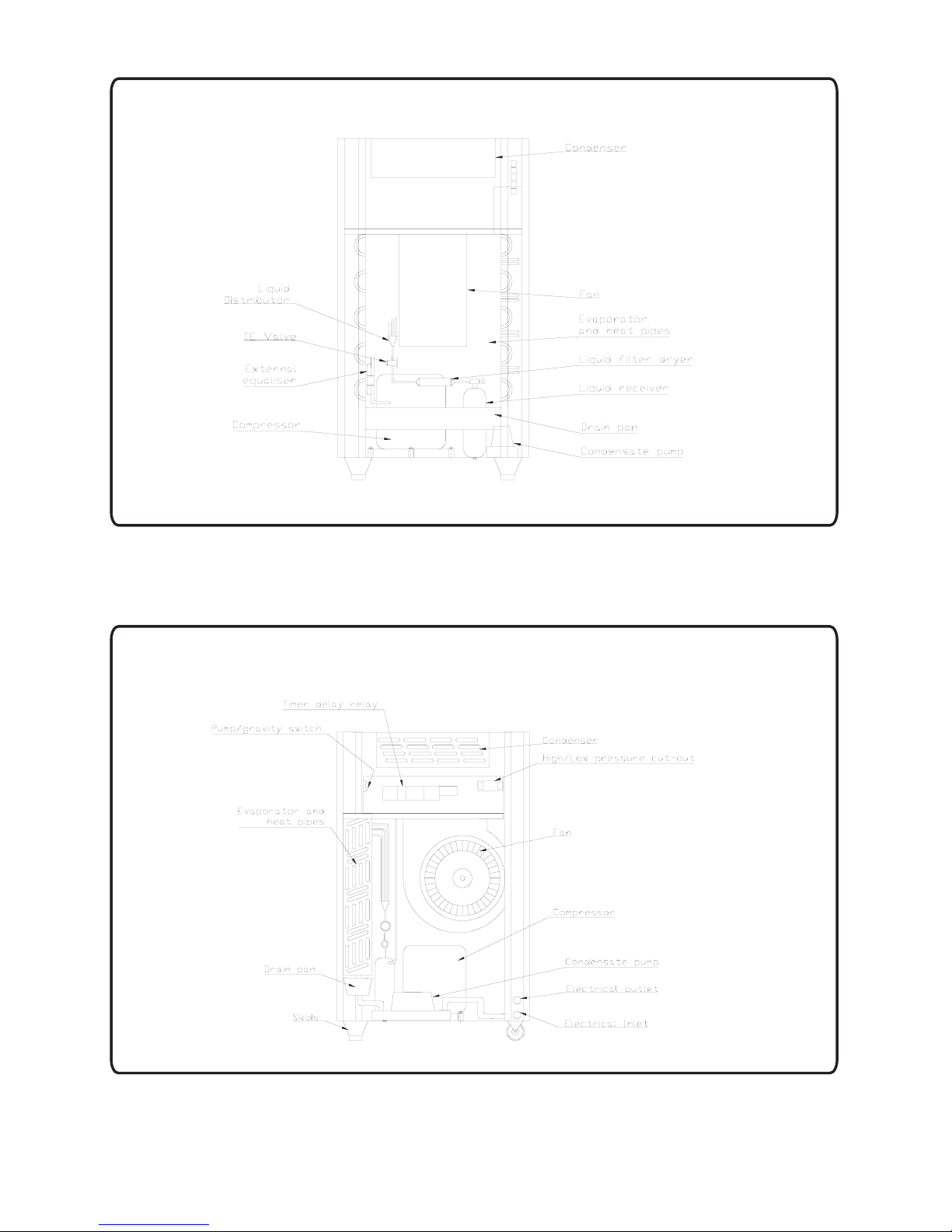
Figure 3. Front view with front panel removed
QA/IOM/46 Issue 11 - MD Dehumidifier
Figure 4. Side view with side panel removed
Page 4
Page 5
1.1. General
The dehumidifiers are mounted on 2 skids at the front and 2 fixed wheels at the back. These allow
secure siting of the units and make provision for local manoeuvring. All units are designed to allow
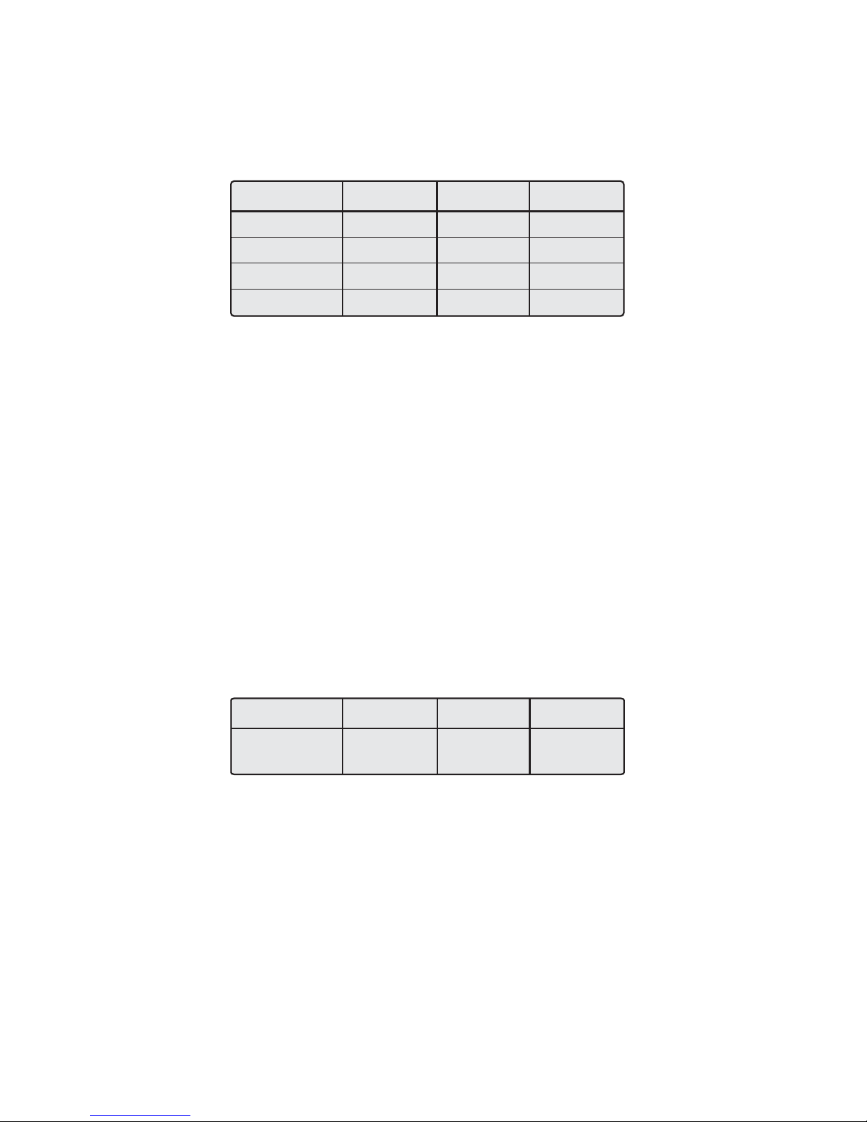
lifting by forklift. Dimension and weights are shown below:
Model
Width (mm)
Depth (mm)
Height (mm)
Weight (mm)
MD100
690
770
920
150
MD160
690
770
1234
169
MD200
690
770
1234
173
VoltageSupply 230V. 4% 50 Hz. Single Phase.
The supply current required byeach model is detailed in Section 4.
The unit is constructedaround 4 'pentapost' type pillars. The panels are screwed into the pillars via a
series of screws and captive nuts fitted inside the pillars. Removal of the side panel allows access to
the control void where the majority of the controls are located. These controls should not be altered
from their factory settings. The upper front panel carries the inlet grille and allows access to the air
filter. This panel sits on the lower front panel supported by studs and is removed by using the keys
provided to unlock the panel,and hinging forward.
The control panel allows switchingbetween different modes, see section 5.
1.2. Refrigeration system
Compressor type: Scroll
Compressor oil type : Mineral
Refrigerant type: R22
Model
Refrigerant
Charge (g)
MD100
1500
MD160
2000
MD200
2200
The evaporator with heat pipesis mounted vertically behind the front grille.
The condenser is mounted horizontallyat the top of the unit belowthe discharge grille.
To prevent the evaporator coil freezing below design range conditions, a low pressure cut-out is
included in the refrigeration system. This detects if the condensateis freezing on the evaporator and
stops the compressor. The coil is allowed to thawpassively before the compressor is restarted.
QA/IOM/46 Issue 11 - MD Dehumidifier
Page 5
Page 6

1.3. Fan and ventilation system
All dehumidifiers use double inlet low-pressure centrifugal direct drive fans fitted with forward
curved impellers.
Restriction or adjustment of the air flow rate has a significant effect on the performance of the units.
Therefore, the inlet and exhaustmust never be obstructed or attempts made to duct theair to or from
the units.
The filters remove air borne dirt from the air and keep the evaporator clean and this should not be
removed, except for cleaning purposes, as indicated in section 6.1. The filters should not be
replaced by other filters withdifferentpressure drop characteristics.
To ensure that the air is drawn through the evaporator, great care has been taken to seal and
insulate all panels. To ensure proper operation the dehumidifier must never be operated with any of
the panels removed. Great careshould also be taken to avoid damageto the seals on the panels.
1.4. Safety features
Compressor on delay
To protect the compressor from hunting, a start delay has been built into the electrical start-up
circuit. It is important thatthis delay is adjusted as this may result in compressordamage.
not
Hi/low pressure cut outs
To protect the compressor from operating at temperatures too high or too low, pressure cut-outs
have been included in the refrigeration circuit. These are mounted in the control void behind the side
panel. Both pressure cut outs are automatically reset when the pressure has returned within the
design range.
The low pressure cut-out is set to prevent operation against conditions which would encourage the
freezing of the evaporator. The coil is allowed to thaw passively should any ice would have built up,
before the compressor is restarted.
High level condensate
If the level of the condensate in the pump drain pan becomes excessively high, the warning light on
the front panel lights up,Figure 10. If this occurs refer tosection 6.2.
QA/IOM/46 Issue 11 - MD Dehumidifier
Page 6
Page 7
1.5. Performance
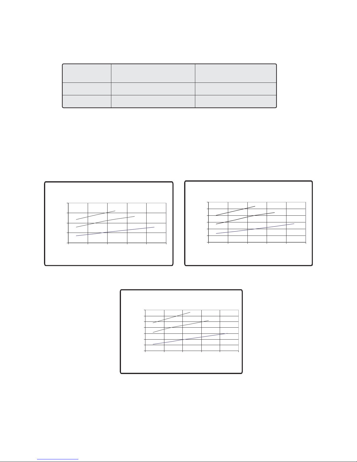
The MD range of Dehumidifiers has been designed to operate between the following conditions:
Dry Bulb Temperature
Lower Limit
Upper Limit
o
(C)
21
40
This corresponds to an approximate minimum wet bulb temperature of 13 C and maximum of 31 C.
Relative Humidity (%)
40
50
oo
Performance is dependant upon both dry bulb temperature and relative humidity as shown in figure
6.
The moisture removal for arange of operating conditions is shown inthe curves below:
100 unit
200
150
100
litres/day
50
0
20 25 30 35 40 45
80%RH
60%RH
40%RH
Temperature (°C)
300
250
200
150
100
litres/day
50
0
20 25 30 35 40 45
160 unit
80%RH
60%RH
40%RH
Temperature (°C)
Figure 6. Dehumidification rates for a range of operating conditions
QA/IOM/46 Issue 11 - MD Dehumidifier
200 unit
350
300
250
200
150
litres/day
100
50
0
80%RH
60%RH
40%RH
20 25 30 35 40 45
Temperature (°C)
Page 7
Page 8

2. PREPARATION OF DEHUMIDIFIER FROM DELIVERY
The dehumidifiers are shipped with the mains cable and condensate discharge hose stored inside
the unit casing.
Once located in the area where the unit is to operate (see section 3.1), the dehumidifier can be
prepared for operation. The side panel should first of all be removed. This will require a Philips
screwdriver to remove the panelfixing screws.
!
!
Remove the side panel
Pass the mains cable through the upper circular hole at the foot of the pillar and
secure with the cable gland.
!
!
Pass the end of thecondensate hose through the lower circular holein the pillar.
The condensate discharge system is designed to operate with the hose supplied.
Under no circumstances should a smaller internal diameter hose be fitted as this will
impair the ability of theunits to discharge the condensate at therequired rate.
!
Place the condensate discharge hose in an appropriate drain. If the dehumidifier is
to be discharged by pump then the drain should not bemore than 2 metres above the
base of the dehumidifier. If the dehumidifier is to discharge by gravity then the hose
must be laid on the floor and taken to a drain that is below the base of the
dehumidifier.
!
The dehumidifier is supplied ready to discharge the condensate by pump. If gravity
discharge is required then referto the operation section 3.2. of thismanual.
!
!
Replace the side panel.
The dehumidifier is supplied with a remote humidistat. This can be positioned either
remotely within the space or mounted directly on to the casing of the dehumidifier. It
is wired into the electrical box via the terminals shown on the wiring diagram. If the
unit is required to operate without the humidistat then these terminals should be
linked together.
!
It is recommended that the unit, once positioned, is stood at rest for 24 hours prior to
operation.
QA/IOM/46 Issue 11 - MD Dehumidifier
Page 8
Page 9

3. GENERAL OPERATING INSTRUCTIONS
This section describes the practicaloperation of the MD range of dehumidifiers.
3.1. Siting of the dehumidifier
The dehumidifiers should never be moved down slopes as they may become unstable and fall over.
To move from one level to another they must be lifted by an appropriate lifting device operated by a
competent person.
The dehumidifier should always be operated on a level surface. The compressor is not designed to
operate in an inclined planeand to do so may result inpremature failure of this component.
The dehumidifier must never be placed in a position where it may be splashed with water or have
water drip onto the casing. As with all electrical equipment of this nature the dehumidifiers should
never be operated with wethands.
Condensate is collected within the dehumidifier and then discharged via the drain hose. To ensure
that this takes place, the dehumidifier must be placed close to a suitable drain point within the
building.
The condensate discharge system is designed to operate with the hose supplied. Under no
circumstances should a longer or smaller internal diameter hose be fitted as this will impair the
ability of the units todischarge the condensate at the required rate.
!
If the dehumidifier is to be discharged by pump then the drain should not be more
than 2 meters above thebase of the dehumidifier.
!
If the dehumidifier is to discharge by gravity then the hose must be laid on the floor
and taken to a drainthat is below the base of thedehumidifier.
It is very important that the drain hose is not crushed or kinked. If this occurs, the pump will not
discharge the condensate, and the dehumidifier will cut out as the high condensate level switch is
operated. If this occurs the amber light on the front panel will light and the fan and compressor will
stop operating.
As the dehumidifier operates, it removes water vapour from the air within the conditioned space,
and the humidity level will gradually fall. This may result in the compressor stopping as the required
humidity level is achieved. The fan will continue to operate in order to circulate the air within the
space being conditioned.
Should the humidity then rise above that required level the compressor will cut back in. The units are
acoustically lined and whilst every effort has been taken to minimise the noise generated by the
compressor on start-up, the intermittent nature of this operation should be considered when
positioning the dehumidifiers.
The panels must never be removed when the mains power is connected. Turn the dehumidifier off
and either remove the plugfrom the socket or isolate the supplyif access is required.
QA/IOM/46 Issue 11 - MD Dehumidifier
Page 9
Page 10

3.2. Changing from pump to gravity condensatedischarge
The condensate removed by the dehumidifier can be removed by pump or gravity to a suitable
drain.
Consideration as to the siting of the dehumidifier in relation to the drain is given in section 3.1.
above.
The dehumidifiers are all supplied with the drain system set up for pumped condensate discharge.
This mode of operation is recommended as it allows the dehumidifier to be sited further away from,
and lower than, the drainpoint.
If gravity discharge of thecondensate is required then change over canbe achieved as follows:
!
!
Remove side panel.
Remove clip and short length of hose between drainpan and condensate pump.
Keep this short length ofhose in a safe place in caseit is subsequently required.
!
Fit the longer length of hose supplied with the unit to the spigot on the drainpan using
the clip supplied.
!
Pass the hose through the lower of the two round holes in the base of the pillar and
run to drain.
!
!
Change the discharge mode switch,shown in figure 4., from pump togravity.
Replace the side panel.
If the drain hose becomes kinked, crushed or the drain point is not below the base of the
dehumidifier then the drain pan will fill and the high level cut out will prevent overflowing of the drain
pan.
If it is required to change the discharge mode from gravity to pump then reverse the above
instructions.
3.3. Fan only / dehumidifying (modesof operation)
The dehumidifiers are designed tooperate in full dehumidifying mode or tooperate in fan mode only.
Fan only mode may be chosen if the humidity level in the conditioned space has been lowered to the
required level but it is still desirable to have air movement within the space to minimise stratification
or air stagnation.
QA/IOM/46 Issue 11 - MD Dehumidifier
Page 10
Page 11
To operate in dehumidifying mode the switch on the front panel should be placed in the dehumidify
position, see figure 10. The dehumidifier will now operate until it is either turned off or the humidity in
the space falls below that set on the humidistat. The required level of humidity should be set by
adjusting the humidistat as required. It is recommended that the dehumidifier is not left running on
the minimum setting as this may reduce the humidity to an unacceptable level. A value between 50
and 60% is recommended for optimum comfort conditions and to minimise the potential of
discomfort for excessive moisture removalfrom building materials.
When the desired level of humidity is reached the compressor will stop. When the humidity rises the
humidistat will sense this and initiate the start sequence for the compressor. This includes a time
delay to prevent hunting of the compressor. Note that if the humidistat setting is reduced to allow the
dehumidifier to operate then the fan will operate immediately, followed by the compressor cutting in
after the delay period.
3.4. Fan speed operation
The speed of the fan can be changed from full to slow using the switch on the front panel, see figure
10.
At slow speed the dehumidification rate is lower than at full speed and the mixing of the air within the
space is reduced. The refrigeration circuit is also more sensitive to variations in changes in air
temperature and relative humidity, which has the result of reducing the operating envelope in which
the dehumidifier will operate.
It is therefore recommended that the dehumidifier be operated at full fan speed at all times. Slow
speed fan operation should onlybe chosen for short periods when the quieter operation ofthis mode
is necessary. When the room is then vacated the dehumidifier must be returned to full speed
operation.
4. INSTALLATION WIRING
VoltageSupply: 230V 4% 50 Hz. Single Phase.
Normal Running Current (A)
Power Consumption (kW)
Supply Current Required (A)
±
Model
MD100
11
2.5
13
MD160 MD200
13
3.1
20
17
3.9
20
The MD100 is suitable forrunning from a 13 Amp supply socket.
Both the MD160 and MD200should be hard-wired from a 20 Amp supply.
Wiring diagrams for the MD100,MD160 andMD200 are shown in figures 7.to 9.
QA/IOM/46 Issue 11 - MD Dehumidifier
Page 11
Page 12
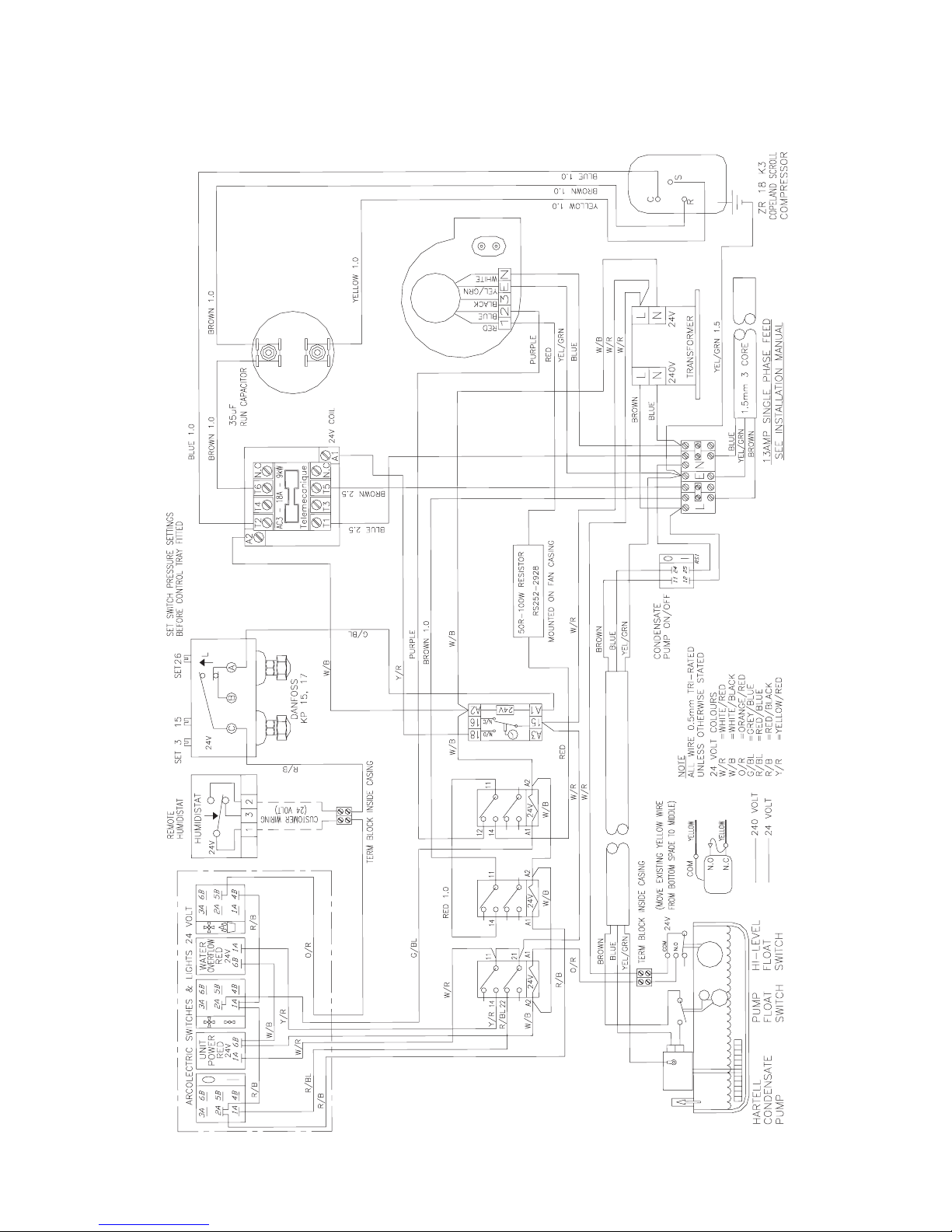
FIGURE 7. WIRING DIAGRAM FOR THE MD100
QA/IOM/46 Issue 11 - MD Dehumidifier
Page 12
Page 13
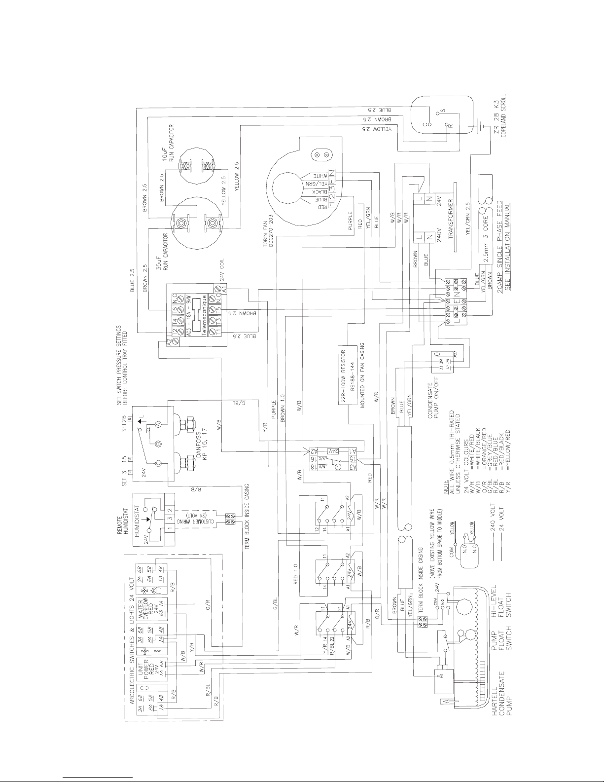
FIGURE 8. WIRING DIAGRAM FOR THE MD160
QA/IOM/46 Issue 11 - MD Dehumidifier
Page 13
Page 14
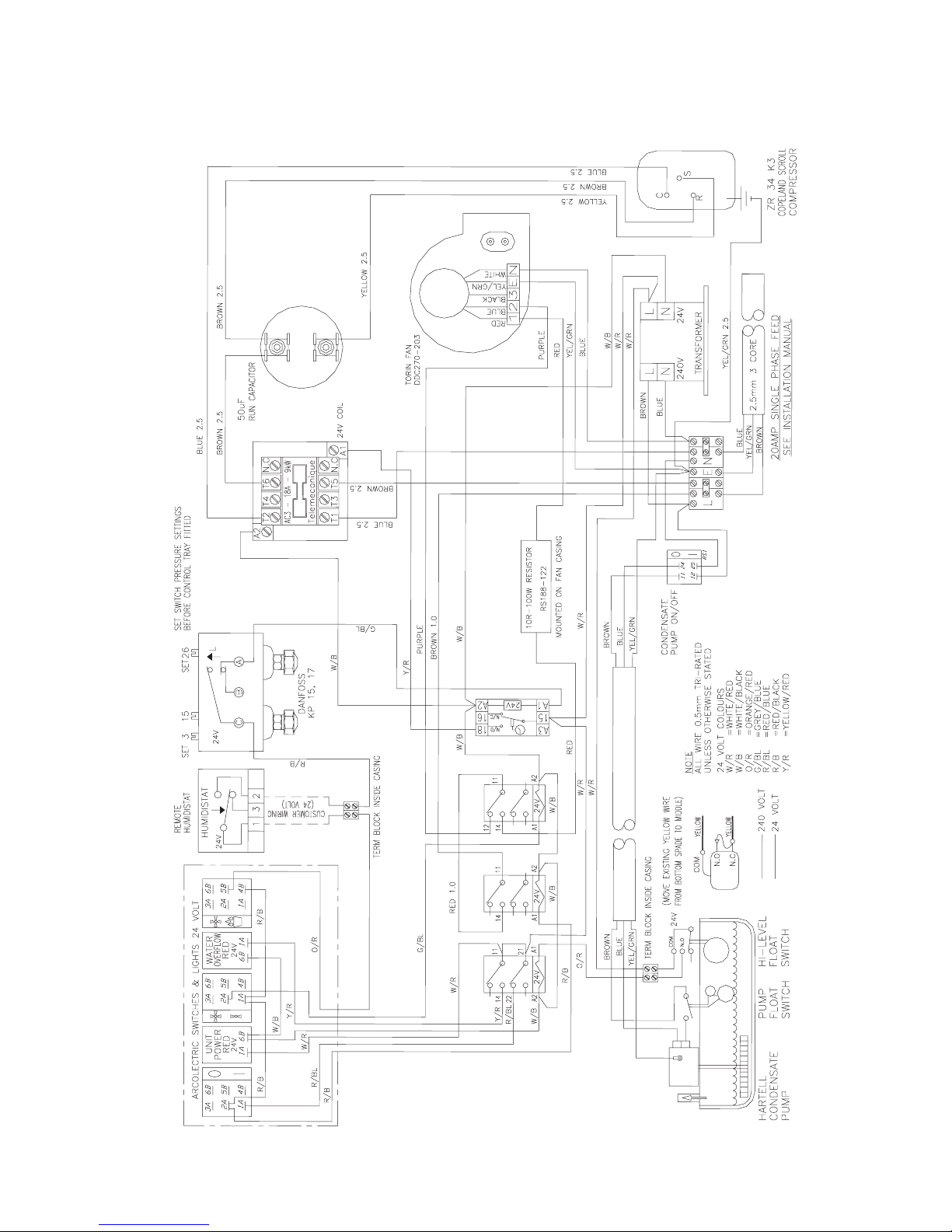
FIGURE 9. WIRING DIAGRAM FOR THE MD200
QA/IOM/46 Issue 11 - MD Dehumidifier
Page 14
Page 15
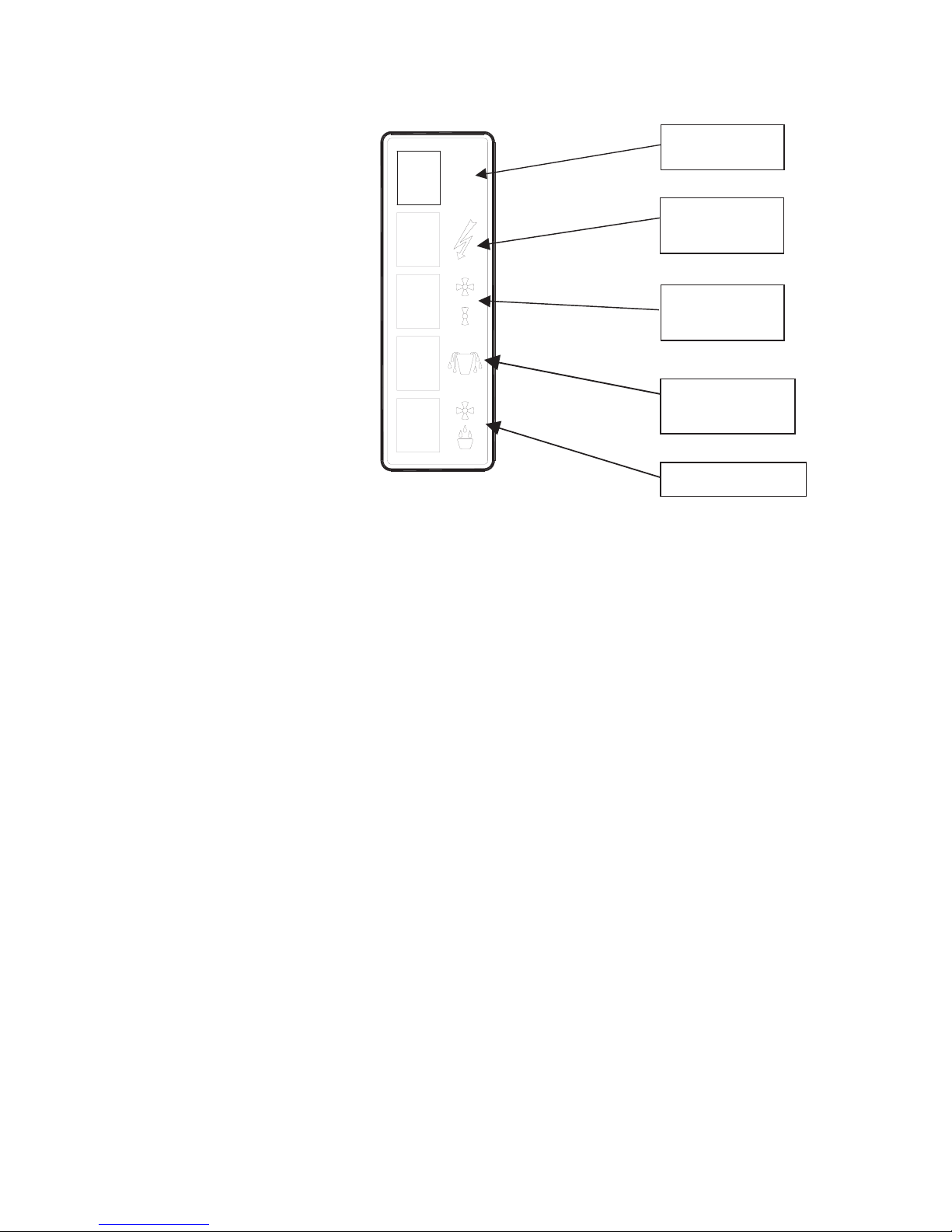
5. CONTROL PANEL
On/Off Switch
0
I
Power to unit
Indicator
Fan speed
Switch
Water overflow
Indicator
Fan only Switch
Figure 10. Layout of control panel on pillar
6. MAINTENANCE AND FAULT FINDING
Electrical and refrigerant work should only be carried out by competent engineers. Work which is not
conducted in accordance with the information contained in these instructions may result in the
warranty becoming void.
6.1 Maintenance
Cleaning of filter
environment. The upper front panel carrying the inlet grille should be removed to gain access to the
filter. This panel is carried on a number of studs, and can be removed by hinging and lifting forward
after unlocking. The filter can be removed from the retaining bracket and cleaned. This involves
gentle tapping to remove accumulated dust and cleaning with a vacuum cleaner. The filters can
also be washed in soapand water and air-dried. Replacement filters areavailable (see Spares List).
Cleaning of drain pan
environment. The side panel should be removed to gain access to the drain pan. The drain pan is
located underneath the evaporator coil, and can be removed by gently twisting the slotted plastic
bracket holding it in place. The drain pan can be cleaned with any proprietary-cleaning agent. For
replacement, reverse the above process.
The panels must never be removed when the mains power is connected. Turn the dehumidifier off
and either remove the plugfrom the socket or isolate the supplywhen access is required.
: Carry out at intervals not exceeding 4 months or more often if in a dirty
: Carry out at intervals not exceeding 4 months or more often if in a dirty
QA/IOM/46 Issue 11 - MD Dehumidifier
Page 15
Page 16

6.2 Faults
Fan not on / redlight not on:
!
!
!
!
Mains power not on
Mains fuse blown
Switch on
Replace fuse
Fan on but compressor not:
!
!
!
!
!
!
Dehumidify / fan only switchis in the fan only position
Start time delay
Defrost cycle in operation
Change to dehumidify
Wait for compressor start time delay tocomplete
Wait for defrost cycle to complete
Pump drain pan full amberlight on:
!
!
!
!
!
Pump drain pan full
Turn off at switch on control panel andmains
Check condensate hose is notblocked or kinked
Check pump / gravity switchis in correct mode for the dischargemode in use
Condensate pump failure. This requires anengineer to investigate
Drain pan overflows:
!
!
Condensate high level switch failure
Float switches are located within the pump drain pan and require an engineer to check
their operation
QA/IOM/46 Issue 11 - MD Dehumidifier
Page 16
Page 17

Compressor on / off allof the time:
!
!
Dehumidifier is operating below itsoperating range and freezing
The humidity of the space is reduced to that required but rises as soon as the
dehumidifier cuts out
!
!
Turn the dehumidifier to operation or off at the mains
The space the dehumidifier is operating in is too small and is causing hunting, move the
dehumidifier to a larger spaceor address the source of the moisturegeneration
6.3. Technical Support
Local supplier:
Telephone/ fax support:
Please quote Supplier, Model Type and unique Serial Number. This can be read from the
serial plate located on theback panel.
7. SPARES LIST
7.1 Electrical
fan only
Humidistat 8AD.P.C.O relays
18Acontactor On delay timer
Switches Condensate pump
Fan
Compressor start kit
7.2 Refrigeration / Mechanical
Air filter Compressor
Thermal expansion valve Liquid line drier
Pressure switch Liquid receiver
Evaporator coil Condenser coil
QA/IOM/46 Issue 11 - MD Dehumidifier
Page 17
Page 18

S & P Coil Products Ltd
SPC House, Evington Valley Road, Leicester, LE5 5LU
Tel: (0116) 249 0044 Fax: (0116) 249 0033
e-mail: [email protected] Web: www.spcoils.co.uk
QA/IOM/46 Issue 11 - MD Dehumidifier
 Loading...